Science Arts & Métiers (SAM)
is an open access repository that collects the work of Arts et Métiers Institute of Technology researchers and makes it freely available over the web where possible.
This is an author-deposited version published in: https://sam.ensam.eu
Handle ID: .http://hdl.handle.net/10985/8593
To cite this version :
Chaima HAMMAMI, Etienne BALMES - Meta-models of repeated dissipative joints for damping design phase - In: International Conference on Noise and Vibration Engineering, Belgium, 2014-09-15 - Proceedings ISMA - 2014
Any correspondence concerning this service should be sent to the repository Administrator : archiveouverte@ensam.eu
Meta-models of repeated dissipative joints for damping
design phase
C. Hammami1, E. Balmes1,2
1
Arts et Métiers Paritech, PIMM
151 boulevard de l’hôpital 75013, Paris, France e-mail: chaima.hammami@ensam.eu
2
SDTools
44 Rue Vergniaud 75013, Paris, France
Abstract
Developing tools to predict dissipation in mechanical assemblies starting from the design process is a subject of increasing interest. Design phases imply numerous computations resulting from the use of families of models with varying properties. Model reduction is thus a critical tool to make such design studies affordable. Existing model reduction methods make computation of models with detailed non-linear parts accessible although costly although allowing the generation of a small size model for the non-linear part. One is, thus, interested in introducing meta-models of the behavior in the non-linear part by determining a basis of principal joint deformations. In this work, one seeks to validate the ability to predict macro-forces associated with the principal deformation shapes. Taking the case of aeronautic structures as cylindrical ones with multiple joints, one seeks to validate the construction of a meta-model associated to the joint. The ability to use such a meta-model to predict damping associated with viscoelastic behavior in a specifically designed bolted joint will be illustrated.
1
Introduction
Damping is a key factor limiting vibration levels. Since structural materials are typically lightly damped, damping occurs at interfaces and designing joints. Maximizing damping is a broadly acknowledged target in many industries and much literature. One can give just a few examples, Refs.[1-2] treat damping in spacecraft structures to reduce vibration levels that can cause its damage, Refs.[3–5] seek to reduce acoustic discomfort in the automotive sector, Refs.[6-7] focus on general purpose testing of bolted joints. This work will focus on the damping generated by bolted joints typical of aeronautic construction, where nearly identical joints are repeated many times. The two main constraints of interest are the ability to perform parametric design studies and thus large number of computations and the use of physically representative models accounting for a lot of details around the joint.
In experimental non-linear joint studies, the classical approach is to derive equivalent meta-models from experiments and seek to reuse them for predictions of the assembled structure. Demonstrating the ability to reuse meta-models is a major challenge and is thus rarely detailed. The idea of this work is thus to address the problem from the new perspective of demonstrating the ability to build meta-models for physically detailed models. The basic idea used for the meta-model construction was detailed in [8] and assumes that one can define principal joint deformations and associate fairly simple joint forces that depend on the joint deformation amplitudes. The originality of this approach is that meta-models are associated with joints rather than modes. One will seek here to validate the ability to use this approach for models with repeated joints.
Addressing the second objective of allowing parametric studies with physical detail around the joint presents a second challenge. Model reduction is a critical tool to make such design studies affordable. The
interest of reduced models with localized non-linearities is well illustrated in recent studies [9–11] and will be followed here. One will fairly classically consider a big sized linear area and a non-linear one with significant details around joints. The first originality is the use of the CMT (Component Mode Tuning) reduction method [12] which gives a small model of the linear part that perfectly matches the system dynamics for a reference linear system. This is achieved by retaining a reduction basis that contains the trace of system modes of the reference linear model.
This reduction makes computation of models with detailed non-linear parts accessible although still costly. Introduction of meta-models can thus be considered to allow faster design computations or to allow easier comparison with experiments.
Section 2 details the decomposition of model degrees of freedom (DOF) into linear and repeated non-linear areas. It is then shown how principal deformations can be defined and generate joint forces that are perfectly decoupled for a reference linear system. Taking the simplified case of a viscoelastic joint with distinct normal and tangential stiffness that are considered design parameters (see [13-14] for similar test cases), it is then shown how various strategies are possible for the approximation of forces generated by the meta-model.
Section 3 then details a sample application using two cylindrical structures connected by 10 bolts. The ability to generate a valid parametric reduced model, using the multi-model approach [15], is first demonstrated. One then analyses the principal joint deformations and sees that accurate meta-models can be found. But proper approximation of joint forces is critical to obtain correct results for large ranges of joint parameters.
2
Meta-models for reduced multi-jointed structures
2.1
Reduced formulations
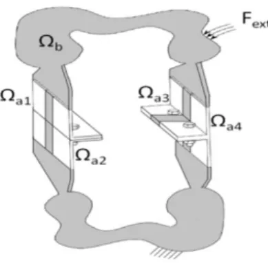
One considers a mechanical assembly fitted with identical bolted joints subjected to dynamic loads shown in Figure 1.
Figure 1: Linear structure with repeated dissipative joints
The equation of motion of the system can be written under the general finite element formulation as follows
[ ] { ̈ } [ ] { } { }
{ } , (1) with the mass, the elastic stiffness matrix, the model DOF, the external force vector and
In the present work [ ]{ }. Parametric studies for design phase computations will thus be
done in the frequency domain so that the equation of motion becomes [ ] { } [ ] { } { }
, (2)
Obviously, this work can be extended to the case of contact and friction forces where the load will depend of position, velocities and possibly internal states describing slip.
The model is first subdivided into two parts: a nonlinear part including bolted joints ( )
and a linear part for all the rest of the structure (Figure 1).
The aim here is to introduce a meta-model able to describe the nonlinear behavior of several joints. This meta-model is built to allow prediction of joint behavior through highlighting principal deformations. The objective is to build a simple model of small size allowing to exhibit simple features to handle. The characterization of the nonlinear forces compared to experiments ([12], [16] and [17]) then can help to improve design. One seeks thus to extend the usefulness of the experimental data from numerical simulations validation to the construction of an experimental database allowing the identification of the meta-model.
The dynamic stiffness of the whole structure is given by
[ ]{ } [ ] { } (3)
The first proposition is that one can describe joint kinematics using a vector subspace of dimension characterizing principal joints deformations. This leads to a change of model DOF characterized by
{ } [ [ ] [ ] [ ] ] { } [ ] { } , (4) where, is the generalized DOF vector which is reduced from to . Model reduction occurs if and/or . The linear part can be reduced by a matrix that can be defined by several reduction methods : Craig-Bampton [18] as proposed in [8] and in most aerospace applications, or the more efficient Component Mode Tuning [12]. The later will be used here but this choice is not the focus of this work. The reduced order formulation of the model defined by equation (2) is thus given by:
[ ] [ ][ ]{ } [ ] { }
(5) One defines a meta-model to be the description of forces associated with a state description of the joint thus allowing the construction of equations of motion. Experimental characterization is done on an elementary joint. One thus considers that the meta-model does not depend on states in the linear part, implies that mass and stiffness contributions of the linear part and coupling terms are not part of the meta-model. Only nonlinear part is thus considered here.
In the present case of viscoelastic damping, an exact joint model is given by
{ } [ ]{ } [ ]{ } (6) with , and respectively the mass, elastic and viscoelastic matrices depending of parameter , associated to one nonlinear part . One will talk about a meta-model, if this model is reduced kinematically by considering a subspace of dimension and/or if simpler expressions of through scalar principal loads are derived.
2.2
Basis of principal joint deformations
As stated in [8], the ideal case would be to have the ability to define independent non-linear forces that only depend on a single state. In the viscoelastic case [13], this would correspond to finding a basis such that the dynamic stiffness is diagonal. This corresponds to the classical modal decomposition,
performed here on the non-linear area around a joint rather than on the whole structure. One defines a linear reference state by choosing reference parameters , and calls [ ] [ ] [ ] the stiffness matrix associated with this reference linear model. In the case of nonlinear contact and friction, a jacobian matrix linearizing the system around a given state would be considered.
The subspace of principal joint deformations is defined as solution of the eigenvalue problem
[ [ ] [ ]] { } { } (7) The associated modes are well known to verify two orthogonality conditions
[ ] [ ] [ ] [ ] (8)
[ ] [ ] [ ] [ ] (9)
It thus appears that both mass and stiffness are diagonal in subspace for . The assumption of [8], that joint forces are decoupled in the basis of principal deformations is thus verified at the nominal point. Since is not diagonalized simultaneously with [ ], it some approximation will occur.
From equation (9) , one can obtain an explicit expression of the inverse of [ ] [ ] [
] (10)
Then, reusing (10) and the fact that from model (4), one has { } [ ]{ } one can obtain the
generalized amplitudes from the full DOF vector using
{ } [ ] [ ]{ } (11) While can be computed for all DOF in , the multi-model reduction approach considers solutions that are a linear combination of simply computed shapes. In the present case, global system modes can be computed for the nominal model. One can thus build a multi-model collection of vectors by combining the six rigid body motion of the joint with the trace of global modes [ ] of the nominal system
on each joint .
[ ] [ ] (12)
One then solves in the subspace generated by this collection of vectors given by model (12), thus obtaining a subspace that can represent nominal system modes exactly. Slight round-off errors are found to occur so an approximation is made, but this approach allows the generation of principal deformation shapes that are characteristic of specific global modes. Keeping rigid body modes is necessary to obtain a meta-model that allows rigid body motion, which is basic requirement for component models [18]. The choice of the reference stiffness is a first key aspect of the proposed procedure and probably its main limitation as will be shown later. The choice of a restricted set of target vectors is the second step that can strongly influence results.
2.3
Meta-model forces
The main goal is to characterize nonlinear forces at joint interfaces through the bolted joint meta-modeling and experimental identification. This section thus details the expression of joint forces. Using
orthogonality conditions defined in (7), (8) and (9) , the meta-model defined in (6) can be transformed to generalized coordinates leading to
{ } [[ ] [ ] [ ] ] { } (13)
If one considers , three joint load approximations are illustrated in this work
FV (Full ) : reduction of and resolution of model (13). The only approximation is in the use of a reduced joint subspace .
VD (full and Diagonalization ): reduction of and resolution of model (13) assuming to be
diagonal
PL (Principal Loads) : approximation of by a singular value decomposition giving principal
loads as follows
∑ { } { } , (14)
with, [ ][ ][ ] where [ ] is a unitary matrices and [ ] is a diagonal matrix of
singular values.
Model (5) can be written under matrix form as following:
[ [ ] [ ] [ ]] { } [ ] { }, (15)
where [ ] [ ][ ] is the reduced nonlinear stiffness matrix of the whole structure, [ ] [ ] [ ][ ] is the reduced mass matrix and [ ] [ ] [ ][ ] is the reduced
stiffness matrix of the reference state.
One notes { } [ ]{ }the jth component of { } with and , and { } [ ]{ }
, the assumption of coupling of principal forces at joints is thus written as following: { } [ ]{ } ∑{ } [ ]{ }
(16)
The second term defines the contribution of local modes on mode . The coupling between forces of the local meta-models introduced in this work is illustrated in section 3. A high level of coupling can be a limitation for the construction of a meta-model faithfully representing the junction behavior.
3
Sample application: cylindrical structure
This section investigates the validity of the reduction approaches with meta-modeling the bolted joints. The aim of the construction of the meta-model method is to build a simplified model that can simulate all the responses for a set of configurations. Therefore, the illustration of objective is to validate the ability of the meta-model to represent the impact of parametric variations of joint properties.
3.1
Cylindrical structure with bolted bracket joints
Aeronautic structures are mechanical assemblies that represent several identical bolted joints distributed over the circumference of the whole junction of two fuselage segments. There are not many works in the literature about structures containing several joints and most application cases considered are prismatic ones. In this paper, one wants to combine these two criterions and highlights the efficiency of handling more realistic cases. One also specifically seeks to treat the bolted bracket joints that are not considered in many researches.
The investigated structure is composed of ten bolted bracket joints shown in Figure 2. This cylindrical structure is a simplified version of a typical aeronautic structure studied in the FUI project MAIAS (Maîtrise des Amortissements Induits dans les ASsemblages). The model is clamped to the ground from the free end of the small inferior box and free elsewhere. To preserve contact area under the bolt head/nut, one defines a perfect contact between plates of the brackets at this area as illustrated in [13]. 3D elements are considered here to represent brackets. Shell elements are considered to model boxes skin and RBE3 bolt model is taken to model bolts. The structure is made of aluminum.
Figure 2: Left: cylindrical model, right: a sector of bolted bracket joint
The model being cyclically symmetric shows pairs of modes at the same frequency but with different bending planes. Figure 3 illustrates both global and local ovalization modes showing mode of various pairs. Dissipation is expected to be higher in global modes that induce higher stresses in the junction.
Figure 3: Mode shapes, from left to right: bending 1, local mode of upper panels, tension, bending 3, torsion, ovalization of the junction
3.2
Parametric study and enrichment of the subspace
The parametric study carried out in this section, focuses on the study of the shear and compression stresses at the viscoelastic material. One thus defines parametric normal and tangent stiffness matrices leading to a joint stiffness [ ] [ ] [ ] where and are the study parameters defining
matrix coefficients.
The reference linear state is defined in this study as function of specific coefficients values and as follows
[ ] [ ] [ ] [ ] (17)
The reduced parametric equation of the whole structure given by model (15) is now written as follows: [ [ ] [ ] [ ]] { } [ ] { }
(18) Based on the multi-model reduction method [15], one proposes here to enrich the subspace with linear local models defining the variation of the normal and tangent stiffness matrix. This enrichment describes transitions between different configurations of joints interfaces behavior. One considers [ ], the subspace defined in equation (12), is now defined as follows:
[ ] [ ] (19)
3.3
Reduction validity on parametric study
The validity of the meta-model construction approaches, detailed in section 2.3, is now investigated. This is done by comparing modal frequencies obtained from a range of full and reduced models. The full response is approximated by the response of the model reduced with the multi-model reduction method (MM) [15], since that method is well validated. This strategy reduces computation time while preserving a sufficient level of accuracy. One chooses here to retain the first thirty modes of the whole structure to define the MM reduction.
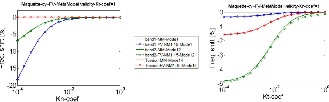
The FV approach is first investigated. The first fifteen double mode shapes of each joint were considered to build the subspace . This choice of reduction is done to describe the first (Mode1) and second bending modes (Mode12) as well as the torsion (Mode14). Figure 4 displays the frequency shift of these modes when varying normal and tangent stiffness at joints interfaces. The MM method and the FV one clearly give very close results. This demonstrates the validity of the FV meta-model with a reduced number of joint deformations. This result is verified for a specific configuration defined by specific local models when enriching the subspace . However, many other configurations can also be defined to build the subspace .
Figure 4: Comparison between multi-model reduction and reduction with FV meta-model
The VD approach is now investigated. One considers a simpler study on the first bending mode ( ), and adjusts the subspace to only retain the first double bending mode at . Figure 5 compares results of the the MM and VD models which neglects coupling of principal joint forces.
A first result is that for the nominal state defined in equation (13), the MM and VD models are matched. Principal loads are thus well defined. For the parametric study the two models diverge rapidly away from the nominal point. The diagonalization of the normal and tangential stiffness matrices is thus not possible for a more important range of parameters.
Figure 5: Comparison between MM reduction and VD meta-model
The PL approach is finally investigated. As before, the model is reduced for the first bending modes ( ).
Figure 6 shows the four principal strain shapes associated to the singular values. Only the first two shapes (Figure 6, a and b) have a high stiffness (above ). They correspond to traction and relative rotation of the brackets. The following are local deformations of the joint.
Reducing joint forces by approximating the stiffness matrix by these two principal joint loads associated to the deformation shapes is thus the PL approach application. Figure 7 shows very close results for the MM and PL models at all design points when varying the tangent stiffness and poorer results for the normal direction. This can be explained by the impossibility to reproduce the decrease of the joint stiffness. Here, the nominal point of reference is taken in a stiff configuration where tangential stiffness has more influence. Proper choice of the reference point thus appears to be a key issue.
(a) (b) (c) (d)
Figure 6: Principal deformations shapes going into the joint, a) axial brackets opening, b) relative rotation of the brackets, c) local axial brackets opening, d) local relative rotation of the brackets
Figure 7: Comparison between multi-model reduction and reduction with PL meta-model
Finally, one seeks to check if one principal load can describe the behavior of one mode (one of the pair of modes). The first bending mode is targeted here as previous case. However, only the first principal load associated to the first deformation shape (Figure 6, a) is taken into account to approximate the normal and tangential stiffness matrices. As shown in Figure 8, the MM and PL approaches match at the nominal point as expected but results away from it, on an important range of design points, diverge. This observation is explained by the fact that the structure presents many joints. Some of them are in opening or closing brackets movements and the others are in relative rotation ones. This combination of stresses cannot be straightforward applied in experiments on classical one-bolted joint model.
4
Conclusion
This work introduced strategies to build meta-models of joint forces. An original aspect is the ability to reuse a single meta-model for repeated joints found in many aeronautic structures. A cylindrical test case was used as an illustration.
The main result is the introduction of a strategy to validate meta-models in their ability to predict multiple operating points. Here, the objective was the impact of joint parameter variations in tangential and normal stiffness on frequencies. Three strategies for defining principal joints deformations and loads were defined. Using a reduced basis of principal joint deformations has shown promising results. Neglecting coupling of principal forces at joints has shown on one hand the validity of the joint principal forces definition for a tangent state of reference, on the another hand poor performance elsewhere. The third strategy, that reduces coupling by using an SVD to determine dominant loads, gave promising results and, while some errors are found, seems the most generally applicable. The combination of different stresses in a single mode pushes to consider more appropriate tests able to properly represent the correct dynamic. The proposed validations clearly need to be extended to cases with more modes and while giving more details on modeshapes and associated damping levels.
References
[1] A. Caignot, P. Ladevèze, D. Néron, and J.-F. Durand, “Virtual testing for the prediction of damping in
joints” Eng. Comput. Swans. Wales, vol. 27, no. 5, pp. 621–644, 2010.
[2] S. LE Loch, “Modélisation et identification de l’amortissement dans les structures spatiales” PHD thesis, Ecole normale supérieure de Cachan, 2003.
[3] Z. Abbadi, “Modélisation prédictive de l’amortissement dans les modèles vibroacoustiques de caisses
automobiles pour la réduction du bruit et vibrations” PHD thesis, Ecole Centrale Paris, 2005.
[4] L. Heller, E. Foltête, and J. Piranda, “Damping identification of assembled structures” Mec. Ind., vol. 7, no. 4, pp. 351–363, 2006.
[5] N. Merlette, Germes S., F. Van Herpe, L. Jézéquel, and D. Aubry, “The use of suitable modal bases
for dynamic prediction of structures containing high damping materials” in Proc, ISMA2004, Leuven,
Belgique, 2004.
[6] L. Gaul, S. Hurlebaus, J. Wirnitzer, and H. Albrecht, “Enhanced damping of lightweight structures by
semi-active join,” Acta Mech., vol. 195, no. 1–4, pp. 249–261, 2008.
[7] S. Bograd, P. Reuss, A. Schmidt, L. Gaul, and M. Mayer, “Modeling the dynamics of mechanical
joints” Mech. Syst. Signal Process., vol. 25, no. 8, pp. 2801–2826, 2011.
[8] H. Festjens, G. Chevallier, and J. L. Dion, “Nonlinear model order reduction of jointed structures for
dynamic analysis” J. Sound Vib., vol. 333, no. 7, pp. 2100–2113, Mar. 2014.
[9] D. Amsallem, M. J. Zahr, and C. Farhat, “Nonlinear model order reduction based on local
reduced-order bases” Int. J. Numer. Methods Eng., vol. 92, no. 10, pp. 891–916, 2012.
[10] D. D. Quinn, “Modal analysis of jointed structures” J. Sound Vib., vol. 331, no. 1, pp. 81–93, 2012. [11] D. J. Segalman, “Model Reduction of Systems With Localized Nonlinearities” Journal of
Computational and Nonlinear Dynamics, 2007.
[12] G. Vermot Des Roches, J. Bianchi, E. Balmes, R. Lemaire, and T. Pasquet, “Using component modes
in a system design process” in Proc. IMAC, 2010.
[13] C. Hammami, E. Balmes, and G. Guskov, “Conception et validation d’une liaison boulonnée
[14] R. Wang, A. Crocombe, G. Richardson, and C. Underwood, “Modelling of damping in small satellite
structures incorportaing bolted joints” in 19th Annual AIAA/USU, Small Satellite Conference, 2005.
[15] E. Balmes, “Parametric families of reduced finite element models. Theory and applications” Mech.
Syst. Signal Process., vol. 10, no. 4, pp. 381–394, 1996.
[16] M. Iranzad and H. Ahmadian, “Identification of nonlinear bolted lap joint models” Comput. Struct., vol. 96–97, pp. 1–8, 2012.
[17] L. Heller, E. Foltête, and J. Piranda, “Experimental identification of nonlinear dynamic properties of
built-up structures” JSV, no. 327, pp. 183–196, 2009.
[18] R. R. Craig, “A review of time-domain and frequency-domain component mode synthesis method” Int