HAL Id: hal-00856691
https://hal-iogs.archives-ouvertes.fr/hal-00856691
Submitted on 2 Sep 2013
HAL is a multi-disciplinary open access
archive for the deposit and dissemination of
sci-entific research documents, whether they are
pub-lished or not. The documents may come from
teaching and research institutions in France or
abroad, or from public or private research centers.
L’archive ouverte pluridisciplinaire HAL, est
destinée au dépôt et à la diffusion de documents
scientifiques de niveau recherche, publiés ou non,
émanant des établissements d’enseignement et de
recherche français ou étrangers, des laboratoires
publics ou privés.
Photorefractive beam-steering system that uses energy
transfer in a BaTiO3 crystal for a fiber-array
interconnect
Pierre Mathey, Raymond Mercier, Gilles Pauliat, Gérald Roosen, Philippe
Gravey
To cite this version:
Pierre Mathey, Raymond Mercier, Gilles Pauliat, Gérald Roosen, Philippe Gravey. Photorefractive
beam-steering system that uses energy transfer in a BaTiO3 crystal for a fiber-array interconnect.
Applied optics, Optical Society of America, 1995, 34 (35), pp.8220-8229. �hal-00856691�
Photorefractive beam-steering system
that uses energy transfer in a
BaTiO
3
crystal for a fiber-array interconnect
P. Mathey, R. Mercier, G. Pauliat, G. Roosen, and Ph. Gravey
A beam-control system to write gratings on a holographic plane is studied. The arrangement is designed to interconnect two 1024 monomode fiber arrays. The beam-control system is composed of two subsystems: a beam steerer, which deflects one incident beam toward 1024 positions, and a collimating system, which adapts the shape of the deflected beam to the holographic plane. The collimating system was studied only after the beam steerer had been fully built and tested. It is based on the photorefractive amplification of a beamlet selected by a shutter array. The deflection efficiency is enhanced by a factor 1500 with the photorefractive crystal, and the signal-to-noise ratio is larger than 5500. The influence of the optical aberrations on the coupling losses of the infrared beams in the monomode fibers are evaluated.
Key words: Optical interconnections, beam steering, microlens array, photorefractive amplifiers, signal-to-noise ratio. r1995 Optical Society of America
1. Introduction
Reconfigurable optical free-space interconnection sys-tems are being actively studied for various applica-tions in photonic switching and interconnects. The roles of these systems are to route signals issued from an array of emitters toward an array of receivers. In telecommunication applications in which high-bit-rate signals 1above 1 Gbyte@s2 are manipulated, it is very desirable to interconnect arrays of single-mode fibers. This could, for instance, permit the realiza-tion of large-scale optical cross-connect systems and to cascade them by the insertion of optical amplifiers. Different free-space interconnection systems have
been proposed. A first architecture is based on the Stanford matrix–vector multiplier,1which broadcasts
power from all inputs to all outputs, and outputs that are not connected to a particular input are shadowed from it by a spatial light modulator 1SLM2. This shadowing yields a power loss, which increases with the number of ports in the system, especially when single-mode fibers are used as output receivers. In principle, using beam deflection avoids this drawback because all the power is directed toward the desired output if the deflection efficiency is high enough. The deflection between one input array and one output array can be realized if several arrays of beam shifters are cascaded,2or if reconfigurable holograms
are used that are written either on an electrically addressed SLM or on an optically addressed SLM. An optically addressed SLM provides the highest resolution and seems to be best suited for routing large numbers of ports1approximately 10002. Some experimental demonstrations of reconfigurable inter-connections by means of hologram arrays have al-ready been presented.3,4 Because all these systems
use a one-hologram array, the direction of the beam arriving at the output receiver depends on the input-port position. This setup is not compatible with single-mode output fibers; for that case, a possible solution is to use a second hologram array, which redirects the deflected beams to a unique direction that is common to all the output ports 1i.e., a two-deflection-stage system2.
When this work was performed P. Mathey, R. Mercier, G. Pauliat, and G. Roosen were with the Institut d’Optique The´orique et Applique´e, Unite´ de Recherche 14 Associe´e au Centre National de la Recherche Scientifique, Centre Scientifique d’Orsay, Baˆt. 503, Boite Postale 147, 91403 Orsay Cedex, France; and Ph. Gravey was with France Te´le´com, Centre National d’ E´ tudes des Te´le´communica-tions, Lannion B, Re´seaux Inte´gre´s Optiques, Processeurs de Commutation Optique, Route de Tre´gastel, Boite Postale 40, 22301 Lannion Cedex, France.
P. Mathey is now with the Universite´ de Bourgogne, Laboratoire de Physique, Mate´riaux pour l’Optique, Unite´ de Recherche 1796 Associe´e au Centre National de la Recherche Scientifique, Baˆt. Mirande, Boite Postale 138, 21004 Dijon Cedex, France.
Received 7 December 1994; revised manuscript received 31 July 1995.
0003-6935@95@358220-10$06.00@0.
We present here a study of an optical addressing system for a 1024-hologram array; the characteristics of this addressing system have been designed to be compatible with the interconnection of two 1024 single-mode-fiber arrays. Particular attention has been devoted to the aberrations introduced by the addressing beams because this point is critical to the achievement of efficient coupling of the deflected beams into single-mode fibers. The system is de-signed to write reconfigurable gratings in an holo-graphic plane, Pc. This holographic plane is
com-posed of N 3 N 5 N2 juxtaposed elementary cells.
In each cell, an elementary grating is written, and it diffracts a collimated beam 1at l 5 1.33 µm2 issued from a monomode fiber of an emission array of N 3
N 5 N2 fibers, toward a single monomode fiber of an
N 3 N 5 N2 fiber reception array 1see Fig. 12.
Updating the gratings reconfigures the interconnec-tions between the two arrays. These gratings are written by means of the interference of two writing beams: one that has a fixed incidence, and one whose direction is adjusted according to the grating that must be written. The holographic plane is made from a photothermoplastic material.5 Each
cell of this plane can be sensitized by a corona discharge and local heating. The writing beams cover the entire holographic plane, and only the sensitized cell is reconfigured. The gratings are thus written sequentially but read in parallel. The recep-tion fiber to be interconnected can be chosen by a change in the fringe spacing of the elementary grat-ing.
The wavelengths of the two writing beams are l 5 514 nm. The sensitivity of the photothermoplastic material is highest for this wavelength, but it must be noted that all the characteristics of the components of the system can be recalculated for any other wave-length. The complete beam-control system is made from the association of two subsystems: first a beam steerer61see Subsection 2.B.2 that permits the
varia-tion of the incident angle of the moveable writing beam, and second a system that adapts the character-istics of the beam issued from the beam steerer to the holographic plane. This second system1see Subsec-tion 2.C.2, called the collimating system, also shapes the second fixed writing beam. In the following paper, the design1Section 22 and the characterization 1Section 32 of the beam-control system are described.
2. System Design
A. Requirements
The design of the beam-control system depends on certain required performances of the interconnect system, as follows:
112 A surface E2 5 E 3 E 5 100 cm2 of the
photothermoplastic plane that is required to intercon-nect two square arrays of N 3 N 5 1024 fibers.
122 The switching time t must be approximately 50 ms,
132 The spatial frequencies 1@L of the gratings must be larger than 200 lines@mm to keep a high
Fig. 1. Schematic diagram of the fiber-interconnection system. Two arrays of N 3 N fibers are interconnected. N 3 N infrared beams
1l 5 1.33 µm2 issued from the emission array are diffracted on N 3 N elementary gratings written in the holographic plane. The elementary gratings are written by the interference of two green beams1l 5 514 nm2: one with a fixed direction, and the other one with
N 3 N addressable directions. The fixed-beam direction depends on the interconnection to be made. The beam-control system comprises a beam steerer and a collimating system.
diffraction efficiency on the photothermoplastic sur-face material,
142 The coupling losses of the deflected infrared beams inside the fibers must be lower than 1.5 dB, i.e., the power coupling coefficient c in a monomode fiber must fit the condition
c $ 71% 112
From points 1 and 2 we can deduce the power POW1for
each writing beam:
POW15 1 2 sE2 t , 122
where s 5 50 µJ@cm2is the sensitivity of the
photother-moplastic material at 514 nm.7
To avoid cross talk, the first-diffraction-order beam must not intersect the second-diffraction-order beam. Taking into account point 3 and condition122, we find the two extreme spatial frequencies that can be written in the holographic plane:
1
L
0
min5 196 lines@mm, 1L
0
max5 331 lines@mm. 132 We deduce that the moveable writing beam has its incidence confined in a solid angle D√ 5 Du13 Df1<4° 3 4°.
Because the fibers used in telecommunication net-works are weakly guiding, the coupling coefficient c and the mean quadratic variation sfof the aberrant
phase fIRof the infrared beam on the entrance face of
the fiber are related by8
c 5 1 2 sf2. 142
According to Gouy’s theorem, phase fIRis equal to the
aberrant phase of the infrared beam just after it passes the photothermoplastic plate. We can easily estimate fIRbecause the aberrant phase of the
infra-red beam incident on the photothermoplastic plane is zero. If we approximate this infrared beam by a plane wave that totally covers an elementary cell in the deflection plane, then fIRis just the phase
aberra-tion of the hologram. It is equal to fIR 5 f1 2 f2,
with f1and f2 being the aberrant phases of the two
writing beams on the elementary cell. From Eq.142 we conclude that c 5 1 2 s1f 12f22 2 $ 1 2 s f1 2 2 s f2 2 , 152 with sf1 2 and sf2 2
as the mean quadratic differences of the aberrant phases of the two writing beams as com-puted for the surface of an elementary cell and assumed to be statistically independent. Condition 152 is highly restrictive, although the aberrant phases are computed on a very small surface, E2@N2.
Indeed if, for instance, the writing wave front presents a small spherical aberration, then the slope of the
phase on the border of the commutation plane will be completely different from the zero slope of the plane wave. Consequently, the aberrant phase on a small cell on the border of the commutation plane will be much larger than the average aberrant phase on the whole commutation plane. High-quality writing beams are thus required.
B. Beam-Steering System 1. Principle
The basic principle of a photorefractive beam-steering system was previously proposed and demonstrated in Ref. 9 1see Fig. 22. A plane wave uniformly illumi-nates an array of N 3 N optical shutters. The array is followed by a lens 1not represented in Fig. 22. Opening one of shutters defines a direction for the transmitted light. There are N 3 N possibilities 1N 3 N shutters2 for the direction of the light. This addressing system, with no mechanical parts, is highly reliable; however, it suffers from poor transmission. The transmitted optical power is at most the input power divided by N 3 N. To compensate for this low efficiency, the weak beam is amplified with two-beam coupling in a photorefractive crystal so as to obtain a deflected beam of adequate power POW1. The main
disadvantage of this system is its low signal-to-noise ratio. The noise comes essentially from the low contrast of the shutter array and from the amplified diffusion of light in the crystal 1the beam-fanning phenomenon2. We show in the next paragraph that the contrast of the shutter arrays available nowadays is sufficient for this application. We also demon-strate that the large amount of amplified scattered light coming from the photorefractive crystal results from an imperfect overlap between the beams in the crystal. In the previously proposed setup,9 the
sig-nal beams were indeed focused in the sample. To reduce the amount of noise we have modified this previously proposed scheme. Our new optical ar-rangement is depicted in Fig. 3.
Fig. 2. Diagram of the principle scheme of a photorefractive deflector as described in Ref. 9. The opening of one shutter defines a beam direction. This beam is amplified by two-wave mixing in a photorefractive crystal.
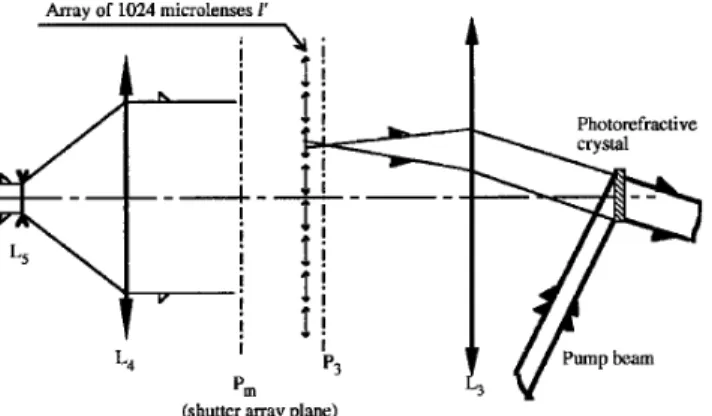
The beam is extended by means of a refractive telescope made of a diverging doublet L51focal length
of f55 250 mm2 and a converging doublet L4 1focal
length of f45 310 mm2. The opened shutter in the
shutter array illuminates one microlens of microlens array l8. The selected microlens focuses the beam in its focal plane P3. The focal lengths of the
micro-lenses are f 8 5 13 mm and their pitches equal 1.09 mm 1see Subsection 2.B.3.2. N 3 N 5 1024 point sources are materialized by this process. Plane P3is also the
object focal plane for lens L3. L3is the association of
a converging doublet of 310 mm and a meniscus lens with a 400-mm focal length. The resulting focal length of this combination is f3 5 177 mm. The
crystal lies in the image focal plane of lens L3. Thus,
all beams from the microlenses are plane waves, and they exactly overlap each other inside the crystal. The pump-beam shape is also adjusted to exactly overlap the other beams.
The shutter array is set in the focal plane Pmof the
microlens array to avoid diffraction on the photorefrac-tive crystal. The collimating system images this crystal onto the holographic plane Pc. Thus, each
shutter is imaged onto Pc.
One should remark that the beam-steering system is designed to address a beam of uniform power in an angular range of DV 5 DU13 DF1< 11° 3 11°. As
shown below, this solid angle cannot be larger because of the angular dependence of the photorefractive gain. The total length of this beam steerer is approximately 120 cm.
2. Shutter Array
Because of the low contrast of the shutter array a nonnegligible part of the transmitted light passes through the closed shutters. Let I0 5 In,m102 be the
probe-beam intensity when shutter 1n, m2 is opened. Beam intensities Ii, j1Co2 that go through the closed
shutters are then
Ii, j1Co2 5
I0
Co
, 162
where Co is the shutter-array contrast.
To write a grating in plane Pc with a modulation
ratio as high as possible, we must have the intensity
I0be greater than the sum of intensities Ii, j1Co2:
I0$1N22 12
I0
Co
. 172
With N 5 32, Co must be greater than or nearly equal to 1000. Commercially available shutter arrays pro-vide such large contrasts, and they are sufficient for our application because the photorefractive amplifier does not modify the ratio of the transmitted beams. Indeed, as described hereafter, the exact overlapping of all beams in the photorefractive crystal makes the contrast of the array seen through the photorefractive amplifier equal to the contrast of the array without an amplifier.
3. Microlens Array
The microlens array is a Model MRP110 array pur-chased from Aeroflex. This array is made of injection-molded methyl methacrylate whose refractive index is nm 5 1.493 at a wavelength of 514 nm. Its
thickness is 5.18 mm. There are 53 3 53 squared plano–convex microlenses. Their pitches are p8 5 1.09 mm. The pitch is equal to the space between each shutter. If the focal lengths are to be increased, their curved surfaces are immersed in an index liquid, as follows:
1a2 Four thickness wedges 1500 µm2 are pasted onto the borders of the Aeroflex MRP110 array with an ultraviolet glue1EPOTEK, NOA 632.
1b2 A glass plate is then pasted on the other sides of the four wedges, thus forming a cell.
1c2 The sides of the cell are sealed with a high-viscosity glue1EPOTEK, No. 7312.
1d2 A hole and a tube to use to fill the cell with an index liquid are added through the glass plate.
1e2 The cell is filled while in vacuum.
The procedure is similar to that used with liquid-crystal screens. The index liquid is an epoxy resin 1EPOTEK, No. 3282. We measured a resulting focal length of f05 13 6 0.2 mm. This microlens array is
remarkably stable after construction: no recanta-tion and no bubbles are observed even after two years.
4. Photorefractive Amplifier
The photorefractive crystal compensates for loss by two-wave mixing three kinds of losses:
x The weak transmission coefficient of the shutter array1t < 18%2,
x The total incident power on the shutter array that is divided by N 3 N, and
x The geometrical losses on the diaphragms of the system1transmission factor pg, 12.
If the total incident power at the entrance of the system is POW05 2 W, the amplification factor f must
Fig. 3. Schematic diagram of the beam deflector. The object focal plane of lens L3is in the image plane of the microlens array l8,
the photorefractive crystal is in the image focal plane of L3, and the
be at least f $ 1 pg N2 t POW1 POW0 . 182
The power POW1 at the exit of the photorefractive
amplifier must be larger than 50 mW 3Eq. 1224. Consequently, the amplification factor f must be larger than 140@pg. One material that satisfies these two
criteria is a BaTiO3 crystal. A high amplification
factor is obtained along with extraordinary polarized light. One source of noise is the buildup of oscilla-tions between the front and the rear faces of the crystal.10 This phenomenon is eliminated with
anti-reflection-coated faces. As discussed above, the diffu-sion of light is also a source of noise. This noise reaches its largest value with extraordinary polarized light and is usually known as beam fanning.10 The
following analysis shows how to reduce this phenom-enon: Because all the waves are plane waves and overlap each other inside the sample, the evolution of the intensity versus coordinate z, along the propaga-tion direcpropaga-tion, is10
5
≠Ii, j1z2 ≠z 5 2aIi, j1z2 1 G 3Ii, j1z243Ip1z24 Ip1z2 1o
k,l51 N Ik,l1z2 ≠Ip1z2 ≠z 5 2aIp1z2 2 G 3Ii, j1z243Ip1z24 Ip1z2 1o
k,l51 N Ik,l1z2 , 192where G is the photorefractive gain, a is the absorp-tion, and Ii, j1z2 represents the intensities of the light
passing through the opened and the closed shutters and also accounts for noise beams. In Eqs. 192 the interactions between beams Ii, j1z2 are neglected
be-cause, in the photorefractive crystal that we use, the large fringe spacings of the interference patterns between these beams make the photorefractive cou-pling much smaller than that between the pump beam Ip1z2 and beams Ii, j1z2, for which the fringe
spacings are much smaller.
These above equations represent the generaliza-tion of two-wave mixing to multiwave mixing. They lead to
5
Ii, j1z2 5 Ii, j102 Ip102 1o
k,l51 N Ik,l102o
k,l51 N Ik,l102 1 Ip102exp12Gz2 exp12az2 Ip1z2 5 Ip102 Ip102 1o
k,l51 N Ik,l102 exp1Gz2o
k,l51 N Ik,l102 1 Ip102 exp12az2 , 1102which can be written as
Ii, j1z2 5 3Ii, j1024 f
3
Ip,o
k,l51N
Ik,l102
4
. 1112So, if all the probe beams overlap each other inside the crystal, the amplification factor f is the same for all the beams. The shutter contrast seen through the photorefractive amplifier is thus the same as the contrast without an amplifier. Moreover, the ampli-fication factor f simultaneously saturates for all probe beams and for diffusion. This simultaneous activity reduces beam fanning.11
This important reduction comes from the exact overlapping of all the beams in the crystal. Indeed, in the case of spatially distinct probe beams, the equations are those of N two-wave mixings. They lead to
Ii, j1z2 5 Ii, j102
Ip102 1 Ii, j102
Ii, j102 1 Ip102exp12Gz2
exp12az2 1122
This last relation shows that, as a result of the saturation of the photorefractive effect, the most amplified beam is the weakest one. In this case, the contrast Co8 of the shutter array that follows the photorefractive amplifier is lower than the contrast Co. From Eq. 1112 and 1122 we conclude that, to achieve a beam-steering system with a large signal-to-noise ratio, all the beamlets plus the pump beam must exactly overlap each other in the crystal.
C. Collimating System
The collimating system is put between the beam steerer and the holographic-commutation plane Pc.
The dimensions of this plane are E 3 E 5 10 cm 3 10 cm. This plane is the image, by passage through the collimating system of the exit face of the photore-fractive crystal, whose dimensions are A 3 A < 5 mm 3 5 mm. The incident angles of the writing beams on plane Pcrange in a solid angle D√ 5 Du13
Df1< 4° 3 4°, which is comparable with the deflection
angle DV 5 DU1 3 DF1 < 11° 3 11° of the
beam-steering system. Thus, the transversed magnifica-tion of the collimating system is M 5 E@A 5 20, and the convergence ratio is 1@g 5 DU1@Du1< 3. For a
centered optical system with an object and an image medium of same refractive indices we have
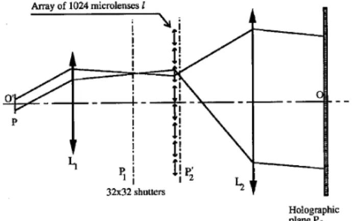
Mg 5 1 1Lagrange–Helmholtz relation2. The only way to break this relation and to achieve M 5 20 and 1@g < 3 is to design an off-axis system. Such a scheme is shown in Fig. 4. The system is composed of a microlens array l inserted between two lenses, L1
and L2. Lens L1is similar to lens L31see Fig. 32. It is
placed after the crystal and it forms a refractive telescope with L3. It images, in a 4f system with a
unit-magnification ratio, the point sources of the microlens foci. The axis of the movable beam, after it passes through lens L1, is parallel to 7O8O8 and is
focused in the focal plane, P1 of lens L1. A shutter
above, the MRP110 microlenses were purchased from Aeroflex. Their pitches were confirmed 11.09 mm2, and their focal lengths were measured 13.2 mm2. One of the microlenses1corresponding to one selected direction2 increases the optical aperture of the beam that is focused in plane P82. P82is also the object focal
plane of lens L2that maintains the plane-wave
struc-ture at the exit of the collimating system. Pcis in the
image focal plane of L2. The writing beam that has
variable incidence angles is always incident at the same place on Pcand illuminates the same useful area
on the photothermoplastic plane. The required focal distance f2 for lens L2 is f2 5 488 mm. We have
designed this lens to fit the wave-front quality require-ments. We have also taken care to leave enough space between that lens and the commutation plane that the infrared beams will be incident on the commutation plane. This lens results from the asso-ciation of four elementary lenses, as shown in Fig. 5. The microlens array is glued onto the first lens 1on the far-left side of Fig. 52. One should remark the important volume of this system1a length of approxi-mately 1 m and a diameter of D2$ 250 mm2. The
total distance between the microlens array and the holographic-commutation plane is approximately 140 cm. The coupling losses resulting from objec-tive L2 must be lower than 30% 3Eq. 1124. The
maximum slopes of the aberrant phase as functions of the point-source positions have been computed and are shown in Fig. 6. The maximum slope is 2.2 3 1025 rad for the writing beam that has a variable
incidence. The maximum slope of the aberrant phase for the fixed writing beam is 1.4 3 1025 rad. The
sum of these two values is lower than 5 3 1025rad,
which corresponds to sf
2 , 0.3%.
The collimating system has been entirely designed and computed, but it has not been manufactured because of its cost. 3. Beam-Steering System Characterization
A. Microlens Array
In the following subsection, several characteristics of the MRP 110 microlenses are analyzed: 112 the qual-ity of their surfaces,122 their focal lengths, and 132 their spherical aberrations.
1. Surface Quality
For this study, the microlens array is illuminated by a plane wave from an argon laser 1l 5 514 nm2. The light is incident upon the curved faces of the micro-lenses. We select the beam from one microlens by putting a pinhole11-mm diameter2 at the focal point of this microlens. The front face of the microlens is imaged onto a CCD array. Two kinds of defects are observed: 112 Scratches, whose widths are much smaller than the size of the microlens illuminating the commutation plane 1these imperfections are not an inconvenience for the system2; and 122 craters, whose highest dimensions are 40 µm and whose depths are of the order of 1 µm 1this last quantity is measured with a Mach–Zehnder interferometer that is described in Subsection 3.A.3. The surface quality of an individual microlens is better at the center and inside a squared 0.7 mm 3 0.7 mm pupil. The cra-ters are sparse and thin in this region and are usually not detected on the corresponding interferograms.
2. Focal-Length Measurement at l 5 514 nm
A parallel-polarized beam of light is incident on the curved face of one microlens. That curved face is imaged onto a CCD array with a microscope objective.
Fig. 4. Sketch of the collimating system. P1is in the object focal
plane of lens L1. The holographic plane Pcis in the image focal plane of lens L2. P, the exit face of the photorefractive crystal;
O8O, the axis of the collimating system.
Fig. 5. Diagram of the exact design of lens L2. The microlens
array is designed to be glued onto the first lens on the left-hand side.
Fig. 6. Maximum phase slope1µrd2 of the wave incident upon the holographic plane as a function of the source point. These sources are located on the first diopter of lens L2. The source points of the
writing beam issued from the beam-steering system are contained in the square and its edges. Point 14, outside the square, represents the fixed writing beam. The microlenses on the sides of the array induce the highest aberrations.
This objective and the CCD array are then moved together by the same amount to image the focal point of the microlens onto a CCD camera. This displace-ment represents the difference between the image plane of the curved face observed through the micro-lens and the focal plane of the micromicro-lens. Conse-quently, it is the focal length of the microlens. Different measurements for many microlenses give a mean focal distance of f05 3.2 mm. The fluctuations
1620 µm2 about this value are included in the measure-ment uncertainties.
3. Aberration Studies
A shadow experiment yielded an estimate of the phase defects. The light source is an Ar laser 1l 5 514 nm2 and illuminates the entire microlens array. One microlens is selected by the placement of a pinhole 11-mm diameter2 at the focal point of the microlens. A diffusing screen is set 150 mm after the array to observe the conical projection of the transmit-ted light; the diffusing screen is then imaged onto a CCD array. This arrangement reveals the local varia-tions in the phase. The slow variations, e.g., spheri-cal aberrations, are not detected with this experiment. However, various defects are observed: dark lines along the microlenses1interferometry reveals that the order of the phase variation is approximately l@10 and is negligible for the application2 and stretches along a diagonal.
A Mach–Zehnder interferometer was used to obtain interferograms of the microlenses. The microlens array is inserted into one arm of the interferometer. One microlens with a pinhole at the focal point of the microlens is selected. The interference pattern is observed on the curved face of the microlens. As shown in Fig. 7, some microlenses are astigmatic, and their interference rings are elliptical. This interfero-gram corresponds to a microlens with the phase defect seen as a dark line in the shadow experiment. Different profiles passing through the centers of the rings are taken, and they give the positions of the
minimum intensities as a function of the interference order. From this curve, the phase defect is deduced and was found to be lower than 0.5l.
All the microlenses do not present the same defects. As an example, Fig. 8 shows the interferogram of another microlens for which the rings are quite circular. For such lenses the only aberration to take into account is the spherical aberration, because all microlenses are illuminated by the same beam at normal incidence. The phase of the transmitted wave at the exit of a microlens is developed by means of the Zernicke polynomials.12 The coupling
coeffi-cient c in a monomode fiber of the reception array is numerically computed as a function of the elementary gratings written in Pc. The most important coupling
losses are for the elementary gratings written on the sides of Pc. If a square, 0.68 mm 3 0.68 mm pupil at
the entrance of a microlens is used, the induced coupling loss remains at approximately sf
2 < 6%.
The coupling losses in this case are thus negligible. In the center of the 53 3 53 microlens array most lenses are acceptable. However, we did not check whether a square containing 32 3 32 microlenses with negligible defects could be found.
In summary, the main parameters, such the focal length, the surface quality, the aberrations, and the corresponding coupling losses induced by these lenses, have been studied. The calculations of the coupling losses coming from the aberrations of the microlenses show that a 0.68 mm 3 0.68 mm pupil can be used, resulting in acceptable losses. These microlenses can thus be used in the collimating system.
The aberrations of the immersed microlens array used for the beam-steering system 1with a focal length of f05 13 mm2 are lower than those in the
initial MRP110 array. The aberrations are reduced by a factor of
1nm2 nair2
1nm2 nliq2
< 4, 1132
Fig. 7. Interferogram of the center 1< 0.6 mm 3 0.4 mm2 of a microlens that presents astigmatism. The interference rings are elliptical.
Fig. 8. Interference pattern of the center of a microlens1the same approximate size as for Fig. 72 that is not astigmatic. The rings are circular, and the corresponding losses are negligible.
where nliqis the refractive index of the EPOTEK 328
epoxy resin 1nliq< 1.41 at l 5 514 nm2. Thus, it is
clear that these aberrations are totally negligible and that it is not useful to measure them.
B. Photorefractive Crystal
The photorefractive amplifier is a barium titanate 1BaTiO32 crystal. The signal-to-noise ratio R of the
crystal must be such that the power of the amplified beam is higher than the noise in the 1N 3 N2 2 1 directions where the beams are cut off:
R $1N22 12 < 1000. 1142
The dimensions of the crystal along the crystallo-graphic axes are aˆ 3 bˆ 3 cˆ 5 3.63 mm 3 5.22 mm 3 5.24 mm, respectively. This crystal sample was bought from the Institute of Physics, Chinese Acad-emy of Sciences, Beijing, China. Its absorption coef-ficient is a 5 0.76 cm21at l 5 514 nm; its trap density,
measured through a two-wave-mixing arrangement,10
is Na 5 2 3 1022m23. The two incident faces aˆ are
l@8 polished so that the coupling losses in a mono-mode fiber in the reception array are numerically computed to be sf2< 0.06%. These two faces are also
antireflection coated to eliminate oscillations between the front and the rear faces. The reflection coeffi-cient of the coating should ensure that the product of the gain times the losses is lower than 1. This leads to a reflection coefficient lower than 4%. We mea-sured it to be lower than 1% at l 5 514 nm. We have verified that the oscillations do not build up with this coating. The quality of the transmitted wave was measured with a Mach–Zehnder interferometer. The interference pattern between the transmitted wave and a reference wave is recorded on a CCD array. This pattern shows that the phase is not uniform. These variations of the phase come from inhomogeneities inside the crystal bulk and from crystal-surface defects. The volume inhomogene-ities are small enough and do not induce significant coupling losses. This is not the case for defects at the surface that result from the rotation of domains during the polishing process. The cˆ axes of the rotated domains are now perpendicular to the en-trance face and so to the cˆ axis of the crystal. The small volume of these domains does not affect amplifi-cation, but it is sufficient to alter the wave front of an extraordinary polarized beam propagating through the crystal. Another BaTiO3sample from the same
origin was studied. This sample was polarized after it was polished and before it was antireflection 1by Virgo Optics, U.S.A.2 coated, and it does not present any microdomains. Although the photorefractive gain of the sample is too low to be useful in our setup, it demonstrates that high-quality samples can be obtained. Interferometric measurements indicate that the coupling losses induced by such a sample are negligible.
C. Beam Steerer
The characterization of the beam-steering system consists of four parts:
112 The phase quality of the transmitted wave; 122 The amplification factor versus the deflected direction;
132 The energetic balance of the system; 142 The signal to noise ratio.
1. Phase Quality of the Transmitted Wave
Because the beamlets cover only a small surface of lenses L1, L2, and L3, the aberrations introduced by
these lens are negligible. As discussed above, the aberrations introduced by the immersed microlenses are also negligible. Most aberrations thus come from the photorefractive crystal. The influence of these aberrations on the deflected beam was measured with a Mach–Zehnder interferometer. The amplified wave interferes with a spherical reference wave, and the resulting interference pattern is recorded on a CCD array placed in an image plane of the photorefractive crystal. The interference pattern reveals aberra-tions larger than l, even when the pump beam is cut off. These defects come from the tilted domains that appear after polishing. With the second crystal sample that is repolarized after it is polished, no such aberrations are observed on the interferograms. This demonstrates that the tilted domains induce nonnegligible aberrations. Unfortunately, the ampli-fication factor of this other sample was too low for the application.
2. Amplification Factors
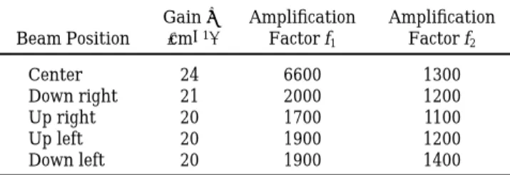
The incident angle for the pump beam is 55°. The average probe-beam incident angle, corresponding to a microlens in the middle of the 32 3 32 array, is 20°. An amplification factor of 6000 1G 5 24 cm212 is
reached if a microlens in the center of the microlens array is selected. The uniformity of the amplifica-tion is studied through the selecamplifica-tion of one microlens in the center of the microlens array or of each of the four microlenses that are in the corners of the 32 3 32 array. The results of the uniformity evalua-tion are listed in Table 1. The measurements of the gain G and of amplification factor f1 are conducted
with a high pump-to-probe beam intensity ratio.
Table 1. Measurements of Amplification Factorsf1andf2as Functions of
the Positions of the Illuminated Microlensesa
Beam Position Gain G 1cm212 Amplification Factor f1 Amplification Factor f2 Center 24 6600 1300 Down right 21 2000 1200 Up right 20 1700 1100 Up left 20 1900 1200 Down left 20 1900 1400 af
1and G were measured through the use of a high pump-to-probe beam intensity ratio, and f1varies by more than a factor of 3. f2 was measured under photorefractive-saturation conditions and is approximately constant.
In this case, amplification factor f1 varies by more
than a factor 3. If one takes into account the Gauss-ian shape of the beam illuminating the microlens array, the amplified-beam intensities vary by more a factor of 7. The measurements of amplification fac-tor f2 are obtained when the pump-to-probe beam
intensity ratio is decreased so that it reaches the saturation of the photorefractive effect. By this means, amplification is smoothed and is more uniform:
f2varies by no more than 610%, which corresponds to
variations of the amplified beams by a factor of 3 only.
3. Energetic Balance
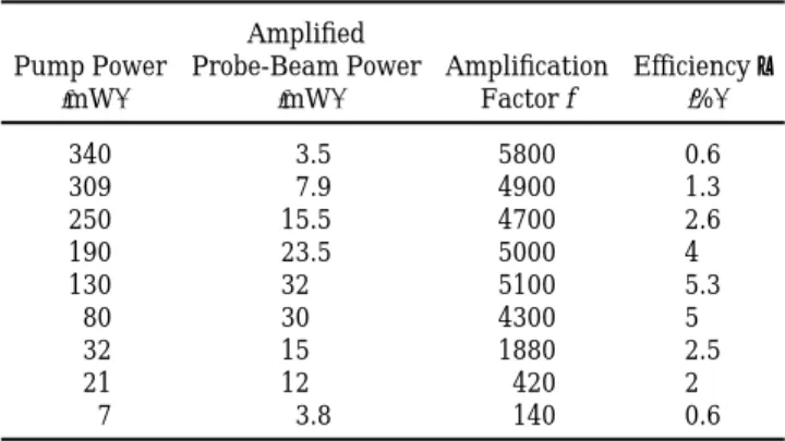
The total power1600 mW2 at the entrance of the beam steerer is divided in two parts. The first, part 1, illuminates the microlens array, while the second, part 2, corresponds to the pump beam. The power of the amplified probe beam is measured as a function of the intensity ratio, part 1@part 2. The results are reported in Table 2. The maximum deflected power is 32 mW. For this value, the efficiency,
h 5power of the deflected beam total power
, 1152
of the beam steerer is 5.3%. In the case of photore-fractive saturation, the efficiency is 2.5% 1row 7 in Table 22. It must be noted that the efficiency is higher than required 1a deflected power of 50 mW is needed for an incident power of 2 W, i.e., h 5 2.5%2.
To demonstrate the performance of the beam steerer, one conducts the following procedure: If all the light power goes through a microlens1an infinite intensity ratio, part 1@part 22, the maximum de-flected power is 21 µW, which yields h 5 0.0035%. This value must be compared with the maximum deflected power132 mW2 when photorefractive ampli-fication is used. The efficiency of the system is increased by a factor of 1500 with the photorefractive
crystal. In consequence, the system reduces the total power for switching by a factor of 1500.
4. Signal-to-Noise Ratio
Optical noise is defined as the diffused-light intensity in the direction of a closed shutter when another shutter is opened. The contrast of the shutter array being high, this source of noise is negligible. For the demonstration, in place of these shutters, we use a cardboard mask. The noise is due essentially to beam fanning. The measurement of the noise is conducted with the worst possible configuration: A microlens in the center is illuminated. The ampli-fication factor is thus at its maximum 160002 and produces a beam-fanning process that is as high as possible. The intensity is also adjusted so as to avoid pump-beam saturation. The amplified signal is mea-sured with a detector in the image plane of the microlens focal plane. We analyze the noise by mov-ing the detector to other focal points that correspond to microlenses that are not illuminated. Noise is at the maximum for microlenses closest to the center. The signal-to-noise ratio is 5500 for the nearest vertical microlenses and 7300 for the nearest horizon-tal microlenses. The noise is greater along the verti-cal axis because of coniverti-cal diffraction. All these values are higher than the maximum value of 1000 required for the system. Even better ratios could be obtained if the intensity pump-to-probe ratio were decreased or if spatial filters were added in the microlenses image plane.
4. Conclusion
A beam-control system for use when gratings are written on a holographic plane has been thoroughly studied. The total length of this system is 260 cm. The whole system is composed of two elements: a beam steerer that directs a beam along one possible direction among N2directions and a collimating
sys-tem that adapts the section and the incidence of the deflected beam to the holographic plane.
We found the following important conclusions: 112 Photorefractive crystals are well adapted to low-noise beam-steering systems. The surface qual-ity of the sample we used was too poor; however, as seen with a second sample, surface-quality defects can be avoided. The signal-to-noise ratio of the beam steerer is larger than 5500. This high ratio is ob-tained when all the beams inside the crystal are overlapped and an antireflection coating is deposited on the faces. The deflection efficiency when such a crystal is used is higher than 2.5%, whereas, at the maximum, it is equal only to 4 3 1025when without a
photorefractive crystal. The power of the deflected beam versus its direction varies by less than a factor of 3.
122 The required coupling coefficient in mono-mode fibers imposes negligible aberrations on the two writing beams.
Table 2. Efficiencyhof the System for Different Pump-to-Probe Beam Intensity Ratiosa Pump Power 1mW2 Amplified Probe-Beam Power 1mW2 Amplification Factor f Efficiency h 1%2 340 3.5 5800 0.6 309 7.9 4900 1.3 250 15.5 4700 2.6 190 23.5 5000 4 130 32 5100 5.3 80 30 4300 5 32 15 1880 2.5 21 12 420 2 7 3.8 140 0.6
aThe intensity ratio comprises parts 1, which illuminates the
microlens array, and 2, the pump beam, of the total power of 600 mW at the entrance of the beam steerer. When no crystal is used and all power goes through the single arm, the efficiency 0.00004%. If one part of the incident beam is used as a pump beam and a crystal is inserted, the efficiency, under photorefractive saturation, increases to 2.5%1see row 72.
We believe that point 2 is the most restrictive. It is in order to achieve such low coupling losses that we have been obliged to design the large and expensive objective labeled L2. Moreover, the size of the whole
system makes its exploitation unrealistic. This point becomes still more critical when one considers that, in principle, a system able to connect 1024 input fibers with 1024 output fibers should consist of two holo-graphic planes, each with its own addressing system. A possible way to avoid this duplication is to split the hologram array into two parts, corresponding to two different arrays of 512 fibers. In this case 1by the addition of an intermediate mirror2 the addressing system that we have studied could permit a two-deflection-stage interconnection system with 512 in-put ports and 512 outin-put ports to be addressed.
This study underlines all the advantages of the use of dynamic couplers based on photorefractive double-phase conjugators.13 With such dynamic couplers a
beacon beam issued from the target monomode fiber attracts the incident beam toward the fiber, thus ensuring large coupling efficiencies. The coupling efficiency is practically independent of the quality of the incident infrared beam. Therefore low-quality writing beams1i.e., spherical waves2 could be used to record gratings in the holographic-commutation plane. These dynamic couplers must therefore considerably simplify the design of the beam-control system. References
1. J. W. Goodman, A. R. Dias, and L. M. Woody, ‘‘Fully parallel, high-speed incoherent optical method for performing discrete Fourier transforms,’’ Opt. Lett. 2, 1–3119782.
2. M. Yamaguchi, T. Matsunaga, S. Shirai, and K. Yukimatsu,
‘‘Analog free-space optical switch structure based on cascaded beam shifters,’’ IEICE Trans. Commun. E77-B122, 163–173 119942.
3. P. Gravey, L. Bonnel, and J. Y. Moisan, ‘‘Preliminary evalua-tion of a 144 144 holographic interconnecevalua-tion system,’’ IEE Conf. Pub.1London2 311, 195–199 119892.
4. H. Yamazaki and M. Yamaguchi, ‘‘Holographic optical switch-ing usswitch-ing a ferroelectric liquid crystal spatial light modulator,’’ paper presented at the International Meeting on Photonic Switching, Minsk, Belarus, 1–3 July 1992, paper 3D4. 5. J. Y. Moisan, P. Gravey, R. Lever, and L. Bonnel, ‘‘Improvement
of photothermoplastic devices for their application to optical switching,’’ Opt. Eng. 25, 151–156119862.
6. P. Mathey, G. Pauliat, and G. Roosen, ‘‘Low-noise two-wave mixing deflector,’’ paper presented at the OSA Topical Meeting on Photorefractive Materials, Effects, and Devices, Kiev, Ukraine, 11–13 August 1993.
7. H. M. Smith, ed., Holographic Recording Materials 1Springer-Verlag, New York, 19772, Chap. 6.
8. A. W. Snyder and J. D. Love, eds., Optical Waveguide Theory 1Chapman and Hall, London, 19832, Chaps. 13 and 20. 9. D. Rak, I. Ledoux, and J. P. Huignard, ‘‘Two-wave mixing and
energy transfer in BaTiO3. Application to laser
beamsteer-ing,’’ Opt. Commun. 49, 302–306119842.
10. P. Gu¨ nter and J. P. Huignard, Photorefractive Materials and
their Applications I, Vol. 61 of the Topics in Applied Physics
Series1Springer-Verlag, Berlin, 19892; Photorefractive
Materi-als and their Applications II, Vol. 62 of the Topics in Applied
Physics Series1Springer-Verlag, Berlin, 19892.
11. M. Segev, Y. Ophir, and B. Fisher, ‘‘Non-linear multi-two-wave mixing, the fanning process, and its bleaching in photorefrac-tive media,’’ Opt. Commun. 77, 265–274119902.
12. M. Born and E. Wolf, Principles of Optics 1Pergamon, New York, 19802.
13. N. Wolffer and P. Gravey, ‘‘High-quality phase conjugation in a double phase conjugate mirror using InP:Fe at 1.3 µm,’’ Opt. Commun. 107, 115–119119942.