ÉCOLE DE TECHNOLOGIE SUPÉRIEURE UNIVERSITÉ DU QUÉBEC
MANUSCRIPT-BASED THESIS PRESENTED TO ÉCOLE DE TECHNOLOGIE SUPÉRIEURE
IN PARTIAL FULFILLEMENT OF THE REQUIREMENTS FOR THE DEGREE OF DOCTOR OF PHILOSOPHY
Ph. D.
BY
Yousef BABA ZADEH BEDOUSTANI
DESIGN AND CONTROL OF A CABLE-DRIVEN 6-DOF LOADING SIMULATOR
MONTREAL, MARCH 31TH, 2015
© Copyright reserved
It is forbidden to reproduce, save or share the content of this document either in whole or in parts. The reader who wishes to print or save this document on any media must first get the permission of the author.
BOARD OF EXAMINERS
THIS THESIS HAS BEEN EVALUATED
BY THE FOLLOWING BOARD OF EXAMINERS
Mr. Pascal Bigras, Thesis Supervisor
Département de génie de la production automatisée at École de technologie supérieure
Mr. Ilian A. Bonev, Thesis Co-supervisor
Département de génie de la production automatisée at École de technologie supérieure
Mr. Zhaoheng Liu, President of the Board of Examiners
Department of Mechanical Engineering at École de technologie supérieure
Mr. Vincent Duchaine, Member of the jury
Département de génie de la production automatisée at École de technologie supérieure
Mr. Mohamed Saad, External Evaluator
Department of Electrical Engineering at Université du Québec en Abitibi-Témiscamingue
THIS THESIS WAS PRENSENTED AND DEFENDED
IN THE PRESENCE OF A BOARD OF EXAMINERS AND PUBLIC FEBRUARY 20TH, 2015
ACKNOWLEDGMENTS
I am very grateful to many special individuals for their generous support, guidance, wisdom, encouragement and inspiration throughout my doctoral studies and dissertation process. First and foremost, I would like to express my sincere gratitude to Professors Pascal Bigras and Ilian Bonev. Words could hardly express how much blessed I was to have them as my directors. The completion of this dissertation would not have been possible without their continuous and tireless support, motivation, and mentoring.
I would also like to extend my deep appreciation to my committee members for their insightful comments on my dissertation.
I also want to thank CORO lab members for their friendship and intuitive discussions specially Andy Yen, Albert Nubiola and Longfei Zhao.
Lastly and most importantly, my deepest gratitude goes to my wife and my parents. This work would not have been done without their love, patience, and support.
CONCEPTION ET COMMANDE D’UN SIMULATEUR DE CHARGE BASÉ SUR UN ROBOT À CÂBLE À 6 DEGRÉS DE LIBERTÉ
Yousef BABA ZADEH BEDOUSTANI
RÉSUMÉ
Dans ce travail, un robot à câbles destiné à la simulation de charges mécaniques (CabOLS) est conçu et construit de façon à contrôler avec précision les efforts dans un espace à 6 degrés de liberté sur une cible fixe ou se déplaçant lentement. Le CabOLS offre plusieurs avantages: la simplicité et l’efficacité de la structure mécanique et du contrôleur, la précision dans la simulation de charge ainsi qu’un faible coût de fabrication. La conception mécanique du CabOLS est novatrice par l’utilisation de ressorts linéaires de précision installés sur chacun des câbles dans le but d’estimer la tension dans les câbles afin d’éviter la nécessité d’ajouter des capteurs de force. Les ressorts servent également à compenser certains effets non-linéaires comme les jeux d’engrenages des réducteurs de vitesses, permettant ainsi de faciliter l’asservissement du mécanisme.
La structure du régulateur est conçue pour être aussi simple que possible. Afin d’exercer un contrôle de force précise sur l’objet cible, deux niveaux de contrôle respectivement dans les espaces des articulations et cartésiennes ont été considérés. La projection optimale de la tension dans les câbles ainsi que la résolution de la redondance des actionneurs en temps réel sont également étudiés dans ce travail. Il est démontré que même si l’algorithme de résolution de la redondance n’est pas linéaire, la combinaison de cette résolution avec le modèle de contrôle du CabOLS est linéaire. Cette linéarité permet de facilité la formulation du calcul des gains dans les deux niveaux de contrôle simultanément.
Cette thèse présente également l'application du CabOLS pour analyser la rigidité d’un robot industriel. Dans un processus automatisé, le CabOLS est contrôlé de façon à exercer une suite d’efforts sur l’effecteur d’un robot ABB. Pour chacun de ces efforts, un laser de poursuite mesure la déviation correspondante de l’effecteur. Ces données sont alors utilisées pour identifier la raideur des articulations du robot. Des modèles linéaire et non-linéaire de raideurs articulaires sont étudiés. Les données obtenues grâce au CabOLS permettent également de valider les paramètres de rigidité identifiés.
Ce travail propose également une formulation généralisée, compact et maniable de la dynamique des manipulateurs à câbles. Cette formulation est novatrice puisqu’elle emploie l’analyse de masse variable s’appuyant sur une approche de Lagrange pour tenir compte de l'effet d’augmentation et de diminution de la masse dû à la variation de longueur des câbles.
Mots clés: Robot parallèle actionné par câbles, simulation de chargement, la résolution de la
redondance, le contrôle de la force, la rigidité du robot, formulation de Lagrange pour masses variables.
DESIGN AND CONTROL OF A CABLE-DRIVEN 6-DOF LOADING SIMULATOR
Yousef BABA ZADEH BEDOUSTANI
ABSTRACT
In this work, Cable-Driven Omnidirectional Loading Simulator (CabOLS) is designed and built to accurately control a 6-DOF wrench on a fixed or slow moving target. The CabOLS offers several important advantages: simplicity and efficiency of the mechanical structure and controller, precision in load simulation as well as the cost efficiency. The mechanical design of CabOLS is innovative in that it employs an accurate linear spring in each cable to estimate the tension in the cable instead of using a force sensor which adds complexity to the design. The spring also compensates for the nonlinear effect of backlash of the gearbox and thereby makes a simple control topology feasible.
The structure of the controller is managed to be as simple as possible without losing efficiency. In order to achieve accurate force control on the target object two levels of control in Cartesian and joint spaces were considered. Optimal projection of the tension in the cables i.e. redundancy resolution is examined in this work. It is proven that even though the redundancy resolution algorithm is nonlinear, the combination of the redundancy resolution algorithm and the model of the CabOLS is linear. Linearity makes it possible to apply robust method to simultaneously formulate the gains of the controller in both spaces. Moreover, the real-time redundancy resolution algorithm was successfully developed and utilized in closed-loop control system.
The present work also demonstrates the application of the CabOLS for stiffness analysis of industrial robots. In an automated process the CabOLS is controlled to exert the desired wrench vector on an ABB robot and a laser tracker is employed to measure the related deflection. Simultaneously, the stiffness of joints is identified by means of the incoming data. In this work nonlinear and linear modeling of the joint stiffness are also formulated. CabOLS as a dynamic load simulator, makes it feasible to identify joint stiffness using either linear or nonlinear modeling. Moreover, the CabOLS makes it possible to validate the identified stiffness parameters.
This work also formulates the generalized, compact, and tractable closed-form of dynamics of cable-driven parallel manipulators. This formulation is innovative in that it employs Lagrangian variable mass analysis to exert the effect of mass streaming caused by cable elongation.
Keywords: Cable-driven parallel manipulator, loading simulator, redundancy resolution,
TABLE OF CONTENTS
Page
INTRODUCTION ...1
CHAPTER 1 LITERATURE REVIEW ...5
1.1 Cable-driven parallel manipulators ...5
1.2 Applications of CDPMs ...8
1.2.1 Existing CDPMs in positioning applications ... 8
1.3 Some loading simulator mechanisms ...14
1.4 Loading simulators in stiffness analysis of robots ...24
CHAPTER 2 LAGRANGIAN DYNAMICS OF CABLE-DRIVEN PARALLEL MANIPULATORS: A VARIABLE MASS FORMULATION ...33
Abstract ...33
2.1 Introduction ...34
2.2 Kinematics analysis of CDPMs ...36
2.3 Kinetic energy of CDPMs ...39
2.4 Variable mass Lagrangian approach ...41
2.4.1 Kinetic energy term ... 41
2.4.2 Generalized forces ... 42
2.4.3 Variable mass term ... 43
2.4.4 Final dynamics equations ... 44
2.5 Case study ...45
2.6 Conclusion ...49
CHAPTER 3 DESIGN AND CONTROL OF A 6-DOF CABLE-DRIVEN LOADING SIMULATOR ...51
Abstract ...51
3.1 Introduction ...52
3.2 System architecture of CabOLS...55
3.2.1 Mechanism description and geometry ... 55
3.2.2 Real-time system, software, and hardware environments ... 57
3.3 Kinematics and Jacobian analysis ...58
3.4 Force control strategy used in CabOLS ...60
3.4.1 Real-time implementation of redundancy resolution ... 61
3.4.2 Control topology ... 64
3.4.3 Inner loops in the joint space ... 65
3.4.4 Outer loop in the Cartesian space ... 70
3.5 Real-time implementation and results ...74
3.6 Conclusion ...76
CHAPTER 4 THE APPLICATION OF CABLE-DRIVEN LOADING SIMULATOR IN STIFFNESS ANALYSIS OF ROBOTIC MANIPULATORS ...81
Abstract ...81
4.1 Introduction ...82
4.2 System architecture ...85
4.2.1 Mechanism and geometry description ... 85
4.2.2 Hardware and software environments ... 87
4.3 The Force control algorithm ...89
4.4 Modeling and identification of joint stiffness ...96
4.4.1 Nonlinear joint stiffness modeling and identification ... 96
4.4.2 Linear joint stiffness modeling and identification ... 98
4.5 Experimental test and results ...99
4.6 Conclusion ...101
GENERAL CONCLUSION ...107
LIST OF TABLES
Page
Table 1.1 Performance comparison of serial robots, parallel robots and CDPMs. ...7
Table 3.1 Identification parameters of each limb in CabOLS ...68
Table 3.2 Gains of the inner loops and the outer loop ...76
Table 4.1 Identification parameters of each limb in CabOLS ...93
Table 4.2 Gains of the control loops. ...96
Table 4.3 Linear stiffness identification for n arbitrary configuration in a desired trajectory (Nm/rad). ...105
LIST OF FIGURES
Page Figure 1.1 A parallel cable robot for carrying loads in ships and seaports. Picture taken
from (Holland et Cannon, 2004) ...9
Figure 1.2 The NIST RoboCrane used to transport equipment. Taken from (Bostelman, Jacoff et Bunch, 1999) ...9
Figure 1.3 (a) The LAR radio telescope (Carlson et al., 2000). (b) The RoboCrane (Bostelman, Jacoff et Bunch, 1999). ...10
Figure 1.4 The SEGESTA cable robot (Fang et al., 2004). ...11
Figure 1.5 The WARP cable robot as a system for virtual reality applications (Tadokoro et al., 2001a; Tadokoro et al., 2001b). ...12
Figure 1.6 The CableCam cable robot. Picture taken from www.cablecam.com. ...13
Figure 1.7 The IPAnema parallel cable robot (Miermeister et Pott, 2010). ...13
Figure 1.8 The MTS loading simulator. Picture taken from www.mts.com ...14
Figure 1.9 The MTS 858.2 MiniBionix spine test fixture with 6 DOF (Jirková et al., 10-12 December 2007). ...15
Figure 1.10 The extension testing set-up. Overview (A) and close-up (B) show pictures of the mounted spine. For flexion testing, the spine is rotated 180° in the mounting fixtures (Kim, Cammisa et Fessler, 2006). ...16
Figure 1.11 The axial rotational testing arrangement (Kim, Cammisa et Fessler, 2006). ....17
Figure 1.12 The R2000 mechanism based on Stewart- Gough mechanism ...18
Figure 1.13 Isolated spine segments testing by R-2000 robot (Kawchuk et al., 2010). ...18
Figure 1.14 The KUKA robot as a spine testing system, Lutheran Hospital Cleveland clinic center, spine health research Lab (Healy et al., 2014). ...19
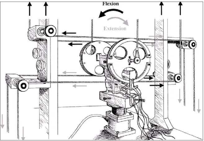
Figure 1.15 Schematic of the cable-driven pure moment mechanism ...20
Figure 1.16 Schematic of the cable-driven pure moment mechanism ...21 Figure 1.17 Close-up of the apparatus set for flexion and extension (Lysack et al., 2000). .22
Figure 1.18 Schematic of the cable-driven pure moment system drive with a MTS
servo-hydraulic mechanism (Eguizabal et al., 2010). ...23
Figure 1.19 The cable-driven pure moment test mechanism with a MTS servo-hydraulic mechanism (Eguizabal et al., 2010). ...24
Figure 1.20 Experimental setup for global stiffness identification, and a schematic of the loading simulator (Alici et Shirinzadeh, 2005). ...25
Figure 1.21 The experimental setup including air cylinder, pulley, steel cable, and digitizer (Jianjun, Hui et Fuhlbrigge, 2009). ...26
Figure 1.22 Experimental setup and the robot end-effector showing the location of the laser tracker reflectors: P10, P11 and P12 (Dumas et al., 2010). ...27
Figure 1.23 Individual joint stiffness identification. The load is applied directly to joints number 1 and 2 (Olabi et al., 2012a). ...28
Figure 1.24 Experimental setup for robot loading and displacement measurement in Cartesian space compliance identification (Slavković et al., 2013). ...29
Figure 1.25 Experimental setup for measuring the displacement of a planar parallel robot. (a) Measurement setup. (b) External force and displacement (Shin et al., 2013a). ...30
Figure 2.1 General structure of cable-driven parallel manipulators (CDPMs). ...35
Figure 2.2 A single limb in a cable-driven parallel manipulator. ...37
Figure 2.3 Simple schematic representation of the planar CDPM. ...45
Figure 2.4 Desired trajectory. ...48
Figure 2.5 Forces and torque in Cartesian space (moving platform workspace); (b) tension in the cables (forces in the joint space). ...50
Figure 3.1 CabOLS fixed to an ABB industrial robot to simulate omnidirectional loading.54 Figure 3.2 (a) Simple schematic of a limb of CabOLS; (b) cable attachments to the mobile platform from above; and (c) cable attachments from below. ...56
Figure 3.3 Real-time implementation of CabOLS. ...57
Figure 3.5 Force control topology of CabOLS: the blue lines indicate the inner loops in the joint space, and the red lines designate the outer loop in the Cartesian space. ...61 Figure 3.6 Force Elongation ratio in an individual limb of CabOLS with spring and
without spring. ...64 Figure 3.7 Inner loops of the CabOLS using position and velocity feedback. ...66 Figure 3.8 Step response of inner loops in which the gains are tuned to place the poles at
P1 = P2 = P3 = −10. First, the spring is used in the limb (ke = 2.20), and then the spring is removed (ke = 10.72). The green line shows the simulated
response of the ideal transfer function 103/(s+10)3. ...70 Figure 3.9 Main loop of CabOLS. ...72 Figure 3.10 Linear model of overall CDPM with inner-loops and the redundancy resolution algorithm which is used in outer-loop. ...74 Figure 3.11 Tracking the desired 6-DOF force/torque in the Cartesian space. ...77 Figure 3.12 Tracking the desired tension in the joint space, which is generated with the
redundancy resolution algorithm. ...78 Figure 3.13 Tension error for each limb in the joint space. ...78 Figure 3.14 Control signal u, the input of the redundancy resolution algorithm, in the
Cartesian space. ...79 Figure 3.15 The positive tension generated with the redundancy resolution algorithm for
each limb. ...79 Figure 3.16 Motor current in each limb. ...80 Figure 4.1 (a) The CabOLS fixed to an ABB IRB 1600 industrial robot to simulate
omnidirectional load and (b) a close-up of the robot’s end-effector. ...84 Figure 4.2 (a) Schematic of a limb of the CabOLS; (b) cable attachments to the mobile
platform from above; and (c) cable attachments from below. ...86 Figure 4.3 Three different combinations of the cable attachment to the moving-platform 87 Figure 4.4 Real-time implementation of CabOLS. ...88 Figure 4.5 Flowchart of automatic operation of CabOLS to collect data for the joint
Figure 4.6 The elongation ratio in an individual limb of CabOLS with the spring and without the spring. ...90 Figure 4.7 The control loops of the CabOLS using position and velocity feedback; and (b)
control loops for each individual limb of the CabOLS with the linear model identified for that limb. ...91 Figure 4.8 The step response of the control loops in which the gains are tuned to place the poles at P1 = P2 = P3 = −10. First, the spring is used in the limb (ke = 2.20), and
then the spring is removed (ke = 10.72). The green line shows the simulated
response of the transfer function. ...95 Figure 4.9 The joint stiffness of the ABB robot is identified in several configurations
along the trajectory (P1 to Pn). It is also validate in an arbitrary configuration V1. ...102 Figure 4.10 The trajectory of the desired tension in the joint space of the CabOLS. ...102 Figure 4.11 The wrench trajectory of the CabOLS in Cartesian space generated by the
desired torque. ...103 Figure 4.12 The deflection in Cartesian space caused by the external wrench trajectory. .103 Figure 4.13 The measured deflection in Cartesian space (red line) for a different applied
LIST OF ABREVIATIONS
3D Three diminutions
CabOLS Cable-driven omnidirectional loading simulator CCT Conservative Congruence Transformation CDPM Cable-Driven Parallel Manipulator
CoRo Control and Robotics Laboratory
CSME Canadian Society of Mechanical Engineer DOF Degree of freedom
ETS École de technologie supérieure KKT Karush-Kuhn-Tucker LAR Large Adaptive Reflector
LIST OF SYMBOLS gr gram kg kilogram m meter mm millimeter N Newton Nm Newton meter
Nm/rad Newton meter per radian rad radian
INTRODUCTION
Cable-driven parallel manipulators (CDPMs) are a unique generation of parallel robots which are becoming increasingly utilized in a variety of applications. CDPMs use cables instead of rigid links to transfer power and to perform motion or wrench on the end-effector. CDPMs offer some high-grade features including the potential of operating in workspaces ranging from large to very small, and that of simple assembly and reconfiguration. They also offer high speed as well as high acceleration, and a high load-to-weight ratio. Based on the requirements of the application, CDPMs can provide workspaces from several centimeters to hundreds of meters. In addition, the outstanding power transmission of the cables allows the manipulator to exert forces/wrenches ranging from several grams to several tons. Accordingly, applications of existing CDPMs are assigned to two categories: i) position control of the moving platform ii) force/wrench control on the target object. A lot of CDPMs have been developed for a vast number of positioning purposes. They include astronomical observation, structure building devices, assembly, rescue, service or rehabilitation, just to name a few. However, for the force control purposes only a few cable mechanisms have been developed. Even the existing ones are not 6-DOF. Furthermore, since they are not fully automated mechanisms, most of them cannot be classified as a robot. Loading simulator, an example of force control purpose, is used in various applications from biomedical and tension analysis of material to stiffness analysis of industrial robots.
The focus of the present thesis is on an application of the CDPM as a 6-DOF loading simulator. In this work, a 6DOF Cable driven omnidirectional loading simulator (CabOLS) is designed and built to precisely control the wrench on a target object, which can move slowly.
Due to complexity of the dynamic analysis of CDPMs, this work started with it using Lagrangian variable mass formulation. A shortcoming of former studies is that they have ignored the effect of mass stream resulting from the elongation of the cables entering into the system (Bedoustani, Taghirad et Aref, 2008). The present thesis is innovative in that it employs Lagrangian variable mass formulation to exert this effect in CDPMs. As a result, a
generalized, compact and tractable closed-form dynamic modeling of the CDPMs was formulated.
Following the initial studies on the dynamics of CDPMs, a 6-DOF loading simulator was designed and assembled. In the mechanical and geometric design stages, cable collision workspace as well as wrench capability were taken into consideration. In the hardware design stage the simplicity of the mechanical components, the actuators, and specifically cost efficiency were emphasized. At this stage, the greatest challenge was to measure the tension in each cable without using any sensors that would increase both the mechanical and electrical complexity as well as the cost. To this end, different approaches were examined. Finally, we came up with an innovative idea to make cables more flexible by adding a precise spring to each limb of the CDPM. The added spring made it possible to estimate the tension in each limb by calculating the elongation of the cable and spring combination. Besides, this innovative and cost-effective method has an added valuable advantage. It effectively compensates for the nonlinear effect of backlash from the actuators and gearboxes. This in turn makes it possible to develop a simple control topology without the need to model nonlinearity effects such as backlash and friction.
In the control stage, different control topologies were verified practically as well as through simulation. Our thesis sought to keep the control topology as simple and efficient as possible. To that end, in order to achieve accurate force control on the target object in Cartesian space, two levels of control, one in Cartesian space and the other in joint space, were considered. The pole placement method was utilized to formulate the gains of the controller in Cartesian and joint space simultaneously. In real-time implementation of the closed-loop control, the real-time redundancy resolution, i.e the optimal projection of positive tension in cables, is critical and presented us with a highly challenging task. This challenging task was performed in this project. Consequently, a combination of the redundancy resolution algorithm and the model of the CDPM in closed loop control were analyzed in this thesis. Because of its significance for control, we aimed at keeping the control topology simple and efficient.
As a next step, the experimental stiffness analysis of industrial robots was evaluated using CabOLS. The stiffness of industrial robots is mostly related to joint flexibility and yields significant errors in tool positioning. Joint flexibility itself is a function of the flexibility of the motor and power transmissions. Robot manufacturers do not present sufficient information on their robots’ joint stiffness. Moreover, the flexibility of the joints could change during long term operation. In order to enhance and maintain the accuracy of robots, therefore, it is essential to perform an experimental stiffness analysis. Such an analysis demands three important elements; i) an automated omni-directional load simulator ii) sufficiently accurate deflection measurements and iii) proper modeling of the joints' stiffness.
The present work demonstrates the use of the CabOLS for stiffness analysis in industrial robots. The CabOLS is controlled to exert the desired wrench vector on an industrial robot in multiple configurations. Nonlinear and linear modeling of the joint stiffness are also formulated in this work, the nonlinear modeling being based on the nonlinearity of the Harmonic Drives employed in each joint of current commercial midsize robots. As a dynamic load simulator, the CabOLS makes it feasible to identify joint stiffness using either linear or nonlinear modeling. This work demonstrates the function of the CabOLS in an experimental stiffness analysis. Moreover, the CabOLS makes it possible to validate the identified stiffness parameters.
The first chapter of this dissertation includes a review of the related literature. The following three chapters present three submitted journal articles based on this work. Due to the complexity of the dynamic analysis of CDPMs, this work began by investigating the dynamic analysis of the CDPMs in general. The first paper includes the results published in The Transactions of the Canadian Society for Mechanical Engineering (CSME). The second paper focuses on the design and control of the CabOLS as a loading simulator. The results were submitted to the Journal of Dynamic Systems, Measurement, and Control. The third paper focuses on innovations to the application of the CabOLS in the stiffness analysis of industrial manipulators and submitted to the journal Robotics and Computer-Integrated Manufacturing. The closing chapter includes the conclusions and plans for future work.
CHAPTER 1
LITERATURE REVIEW
1.1 Cable-driven parallel manipulators
In recent years, much work has been done on various types of parallel manipulators. The Stewart-Gough mechanism is one of the most widely-used robots in this category and the properties of this class of parallel robot have been studied by Merlet in (Merlet, 2006). Parallel robots have low structural weight compared to serial manipulators. They are very rigid because of their mechanical closed-chain structure and also they have high accuracy in positioning. However, limited workspace is their main disadvantage. Another emerging class of parallel robots is the cable-driven parallel manipulators (CDPMs). The flexibility of their cables is the most important distinguishing difference between CDPMs and other general parallel robots. In fact, cable dynamics and restrictions play a key role in their overall dynamics. In other words CDPM inherits cable properties including cable restriction in the transmission of force in one direction.
Some advantages of cable-driven parallel manipulators are as follows (Barrette et Gosselin, 2005a):
• Workspace ranges from very small to very large areas (from several centimeters to several hundred meters) because cables take up only a little space when rolled around a pulley,
• CDPMs have low structural weight, not only due to the low weight of the cables, but also because the actuators are fixed and located away from the manipulator,
• Cables, motors, and cable wrench mechanisms combined are less expensive than other actuators such as hydraulic ones, which are widely used in parallel robots, • Cables as links in CDPMs allow a flexible configuration,
However, the end-effector (moving-platform) must be positioned without exceeding several limitations:
• The cables must always be in tension (forces must be positive),
• The cable forces must be less than the maximum tension values (cable failure), • The moving platform must avoid regions of singularities,
• The cables must not collide with each other or with the moving platform.
A major characteristic of CDPMs needs to be remembered: cable dynamic redundancy is unavoidable. In fact, redundancy is necessary in cable robot design in order to satisfy the positive tension constraint in cables. Subsequently, redundancy in cable robots introduces complexities into the kinematic analysis, dynamic analysis, optimal force distribution (redundancy resolution) and control design. Table 1.1 briefly compares the performance of serial robots, parallel robots and CDPMs.
Table 1.1 Performance comparison of serial robots, parallel robots and CDPMs.
Properties Serial robot Parallel robot CDPMs
Stiffness Low High Medium
Workspace Medium Low High
Singular points Low High Medium
Load on each link
Whole of external load+ end-effector & tools+
actuators+ provirus-links
Part of external load+ end-effector & tools+
actuators
Part of external load+ end-effector & tools
Bending load on link High Medium Zero
Axial load Medium Compression/ Tension High Compression / Tension High Tension only
Velocity-Acceleration Medium High High
Inertia of system High Low Low
Fabrication of links Medium Hard Easy
Accuracy Low High Average
Complexity of
processing Low High High
Failure in one link Loses its connectivity Fails-without safety
Normal Safe
Normal Safe
Manufacturing cost Medium High Low
Performance as a loading simulator
1.2 Applications of CDPMs
Performance specifications of CDPMs such as speed, payload and workspace can be adapted to a wide range of applications. Workspaces of several centimeters up to hundred meters can be achieved for required applications. Payloads ranging from several grams to several tons are possible due to the outstanding power transmission of the cables. Applications of existing CDPMs could potentially be assigned to two categories of positioning and loading simulators. Currently, whereas many CDPMs have been developed for positioning purposes, only a few cable mechanisms have been developed for loading simulator applications and even the existing cable mechanisms are not 6-DOF loading simulators. Moreover, most of them could not be categorized as a robot since they are not fully automated mechanisms. The following three subsections briefly present existing CDPMs in positioning applications, some robotic mechanisms and cable mechanisms as loading simulators, respectively.
1.2.1 Existing CDPMs in positioning applications
The crane is one of the primary cable mechanisms used for positioning for example see figure 1.1 . The first generation of RoboCrane was built in 1985 by Landsberger and Sheridan (Landsberger et Sheridan, 1985). Thereafter, plenty of robots have been developed for different applications based on this concept, one of the most prevalent being carrying containers in seaports (Holland et Cannon, 2004; Thompson et Campbell, 1996). The NIST RoboCrane is used to transport equipment and tools (see figure 1.2) (Bostelman, Jacoff et Bunch, 1999). However, this design, which is largely based on gravity to maintain the tension on the cables, is only suitable for a limited class of tasks. Using gravity for putting containers on board a ship is indeed suitable, but not for applications such as machining. Furthermore, this type of robot can only work at low acceleration and with absolutely minimal disturbance. Moreover, workspace is one of the most important issues when designing this robot.
Figure 1.1 A parallel cable robot for carrying loads in ships and seaports. Picture
taken from (Holland et Cannon, 2004)
Figure 1.2 The NIST RoboCrane used to transport equipment. Taken from (Bostelman, Jacoff et Bunch, 1999)
In some CDPM designs such as the LAR radio-telescope (Carlson et al., 2000) a vast workspace as well as accuracy in position are required (see figure 1.3). In the LAR radio-telescope, a hydrogen balloon is used to keep the cable in a tension state while, in the RoboCrane (Holland et Cannon, 2004) (Durrant-Whyte, Dissanayke et Rye, Oct.3, 2000), Earth’s gravity is used for this purpose.
The SEGESTA cable robot (figure 1.4) was designed and built to implement a control algorithm specially formulated for applications that require high velocities (Fang et al., 2004). It has seven cable actuators located at the corners of the base such that it minimizes possible cable contact (Hiller et al., 2005). Obviously, it is impossible to have tension on cables at all points within the workspace. Furthermore, a dynamic analysis of the robot in the workspace is required to calculate the forces in actuator space (Bruckmann et al., 2007).
(a) (b)
Figure 1.3 (a) The LAR radio telescope (Carlson et al., 2000). (b) The RoboCrane (Bostelman, Jacoff et Bunch, 1999).
In the application of virtual reality systems such as auto-pilot simulations, Tadokoro et al. replace the Stewart-Gough mechanism with a WARP cable robot (Tadokoro et al., 2001a; Tadokoro et al., 2001b). The rationale is that, although the Stewart-Gough parallel robot is one of the most widely used structures in the above mentioned applications, its architecture presents problems like (Tadokoro et al., 2001a):
• The large space needed for installation because of hydraulic cylinder actuators, • The range of possible acceleration for a long period is limited,
• The possible magnitude and time of acceleration are restricted, • The rotational range of motion is small,
• The necessity for spherical joints in the tow side of the prismatic hydraulic joint (complex SPS joint).
These problems, along with the restrictions of this mechanism in the workspace, lead designers to consider other structures, like the WARP cable robot (Tadokoro et al., 2001a; Tadokoro et al., 2001b). This particular mechanism is driven by multiple cable wires suspended from various directions to move a platform in 6 DOF and its architecture covers
most of the problems inherent in the Stewart-Gough structure. In order to solve the force problem, the WARP mechanism (figure 1.5) uses eight cables. This redundant architecture has advantages such as enhancing safety in case of cable failure, improving workspace, and solving redundancy problems by the optimal distribution of forces in joint space.
The potential of using cable robots for covering very large workspaces is exploited by companies like SkyCam and CableCam. The SkyCam cable robot was in fact a turning point in broadcasting and high definition live capture of sporting events. To achieve good motion control, these cable robots employ two sweeping cables in each Cartesian direction. However, each sweeping pair of cables has the same actuator (see figure 1.6). In other words, the tension force problem in cables is solved and guaranteed by the mechanical design.
Figure 1.5 The WARP cable robot as a system for virtual reality applications (Tadokoro et al., 2001a; Tadokoro et al., 2001b).
The CDPM demonstrator IPAnema at Fraunhofer IPA achieves performance characteristics beyond the capabilities of conventional industrial robots. One of its key features is to reach high speeds of up to 2.5 m/s. There are many more CDPMs in positioning applications. However, we selectively mention some only.
Figure 1.6 The CableCam cable robot. Picture taken from www.cablecam.com.
1.3 Some loading simulator mechanisms
The Bionix Servo-hydraulic (figure 1.8) is a multipurpose test mechanism developed by the MTS Company. This compact system is designed to study the mechanical properties of biomaterials, medical devices and orthopedic constructs (Voor et al., 1998). It is also used to obtain the full spectrum of spine dynamics. This dynamic simulation is required in biomedical investigations and especially orthopedic research. The mechanism is released in only two configurations: axial and axial-tensional. The axial configuration is designed to perform accurate and repeatable fatigue studies, and also tension, bending and compression tests of biomaterials. The axial-tensional configuration is well-suited to testing durability and wear in components such as knee, hip, and spine implants. It can also be used for studying surgical techniques and conducting complex kinematic studies of joints, tissues and orthopedic constructions (Voor et al., 1998). Notwithstanding this mechanism can apply forces in one direction only and moments of inertia around one axis. In other words, it has only two DOF. Moreover, there is serious restriction in the video capture and x-ray radiography of models during tests. These disadvantages are regardless of its high price.
The MTS 858.2 MiniBionix is a special spine test fixture with six degrees-of-freedom (Jirková et al., 10-12 December 2007). This system, shown in figure 1.9, allows the operator to perform a wide variety of spinal column kinematic studies. Moreover, the system makes it possible to have axial force and moment at the same time. It can also measure the bending moment, axial loads, or a combination of torsion or flexural motions. Its mechanism involves multi-channel and axial/torsion systems for analyzing both skeletal and soft tissue during surgical treatment and, due to the use of servo-hydraulic actuators, it operates in low friction and high stiffness. Therefore, it can easily simulate human spine dynamics. This simulator is, however, extremely complex. Moreover, the hydraulic actuators are difficult to control precisely. They also require a hydraulic pump.
Figure 1.10 shows another mechanism which has been used by Professor Dennis J. DiAngelo at University of Tennessee Health Science Center as a spinal testing device (Kim,
Figure 1.9 The MTS 858.2 MiniBionix spine test fixture with 6 DOF (Jirková et al.,
Cammisa et Fessler, 2006). This system consists of a two-column frame housing a servomotor connected to the controller (Chen, 1996; DiAngelo et al., 2000; Faber, DiAngelo et Foley, 1997; Jirkova et al., 2007). As shown in figure 1.11, a single-axis force sensor is attached to one end of the actuator shaft. On the other end, it is connected to fixtures containing a pinned connection and a linear bearing for attaching the machine to the cervical spine.This system has two degrees of freedom. In fact, the mounting fixtures that are added to it allow unconstrained motion and rotation in a plane. The flexion/extension axis of the spine is placed against the load axis of the actuator. Therefore, a compressive load, and a flexion/extension bending moment are applied to the upper holder. For some tests, like lateral bending tests, the spine is first rotated through 90° in the mounting fixtures, and then the base is left unconstrained in an axial rotation. As shown in figure 1.10 (A), a rotational displacement transducer is attached to the upper pinned assembly and measures the global rotation of the spine. This approach restricts the motion to two degrees of freedom.
Figure 1.10 The extension testing set-up. Overview (A) and close-up (B) show pictures of the mounted spine. For flexion testing, the spine is rotated 180° in the
The R- 2000 parallel manipulator from Rotopod Parallel Robotic Corporation (Hampton, NH) is another mechanism, which has been used by Prof. Gregory N. Kawchuk of Alberta University as a loading simulator spine testing applications (see figure 1.12) (Kawchuk et al., 2010). This parallel robot is based on a Stewart- Gough mechanism. The system is composed of an upper and a lower test fixture. The upper fixture is fastened to a cross-beam attached to the base of the robot. The lower fixture is mounted on the six- axis load cell which is attached to the R-2000 robot test platform (Goertzen et Kawchuk, 2009) shown in figure 1.13. Similar to other Stewart-Gough platforms, this mechanism does not allow extensive displacements. Its mechanical design is complex: it has a big structural frame and it uses hydraulic actuators, which make it expensive.
Figure 1.11 The axial rotational testing arrangement (Kim, Cammisa et Fessler,
Figure 1.12 The R2000 mechanism based on Stewart- Gough mechanism (Kawchuk et al., 2010).
Another mechanism, which has been used at Lutheran Hospital, Cleveland, is a serial robotic manipulator. The spine health research lab, led by Professor Lars Gilbertson, especially focuses on advancing the basis of new therapies for spine disorders. To that end, the well-known KUKA robot is employed to apply forces to the spine model (Healy et al., 2014) (see figure 1.14). However, stable and robust contact force control schemes for a rigid robot (such as KUKA) in contact with a rigid environment is very hard problem. In fact, it involves the formulation of highly nonlinear dynamics for the constrained robot, which results in very high bandwidths. Hence, the digital control requires very high sample rates. Also, it is very difficult to find robust solutions to modeling errors such as friction in the drive systems, poor knowledge of the actual robot dynamics, contact stiffness, and contact geometry (DeSchutter et al., 1997).
The cable mechanism, designed by Crawford in (Eguizabal et al., 2010), was used by biomechanical engineers. This mechanism was designed to apply only pure moment to the
Figure 1.14 The KUKA robot as a spine testing system, Lutheran Hospital Cleveland clinic center, spine health research Lab (Healy et al., 2014).
spine specimen. Figure 1.15 shows one such design whose mechanism has been optimized for the purpose of maintaining a continuous load on the spine (J.P. Dickey August 14-18, 1998 ).
The specimen is mounted in the center while the force sensor is fixed at the bottom. The load wheel then applies the loads to the top of the spine segment. The shaft, shown at the top of figure 1.15, is used to move the pulley carriage; it can also be used for applying vertical force to the counterweight mechanism (or to systems like the MTS mechanism.). The movement of the pulley carriage creates equal and opposite cable forces on the larger load wheel, causing a pure flexion moment. Also, a constant extension moment can be applied to the smaller wheels by cables acting around pulleys and hanging masses that are not shown in this figure. Figures 1.16 and 1.17 show a similar design to load apparatus for applying continuous pure
Figure 1.15 Schematic of the cable-driven pure moment mechanism (J.P. Dickey August 14-18, 1998 ).
moment to multi-segment spine specimens (Lysack et al., 2000). This design allows a continuous cycling of the spine between specified flexion and extension.
Figure 1.16 Schematic of the cable-driven pure moment mechanism (Lysack et al., 2000).
The latest mechanism, shown in figures 1.18 and 1.19, is another cable-driven pure moment system, also based on the Crawford design (Eguizabal et al., 2010). This system is actuated by a MTS Servo-hydraulic test mechanism. Similar to the Crawford cable mechanism, it consists of a loading ring attached to the spine model. A Spectra cable with a 200 lb capacity is wound around the loading ring in a suitable configuration. This structure provides either flexion or extension forces on the spine specimen. The cable is then routed to the actuator via low friction pulleys fixed to the master frame. The position of the pulleys must be adjusted before starting the tests (Eguizabal et al., 2010).
Figure 1.17 Close-up of the apparatus set for flexion and extension (Lysack et al., 2000).
The cable mechanism designed by Crawford in (Eguizabal et al., 2010), is completely reliable for valid test conditions (J.P. Dickey August 14-18, 1998 ). However, these structures are limited in their degree of freedom. Moreover, its mechanical design is complicated. It could be even more complex to improve this mechanism in order to have more degree of freedom.
Figure 1.18 Schematic of the cable-driven pure moment system drive with a MTS servo-hydraulic mechanism (Eguizabal et al., 2010).
1.4 Loading simulators in stiffness analysis of robots
Experimental stiffness analysis needs a setup that includes a load simulator and a device such as a laser tracker for accurate deflection measurements. The load simulator simulates external loads on the end-effector of a serial or parallel robot. The deflection caused by this load is simultaneously measured. The collected force-deflection data is used for the joint or Cartesian stiffness identification of the manipulators. The first example of an experimental loading simulator used for stiffness analysis is shown in figure 1.20 (Alici et Shirinzadeh, 2005). This setup allowed the investigation of a serial robot's global stiffness. The external force was exerted on the point of the robot using a simple pulley system. The end-effector position and orientation deflection under load were measured by a laser tracker.
Figure 1.19 The cable-driven pure moment test mechanism with a MTS servo-hydraulic
Figure 1.21 shows another experimental setup (Jianjun, Hui et Fuhlbrigge, 2009). In this setup the external force is imposed by an air cylinder through a pulley relayed steel cable. The amplitude of the external load can be adjusted by changing the air pressure. The direction of the load can be varied by changing the position of the pulley on the base column. In this manual setup, it is not possible to apply torque because of the point connection of the string to the robot's end-effector. In this setup, by using static equilibrium, the force vector at the force action coordinate is the same as the one at the force sensor coordinate. Three
Figure 1.20 Experimental setup for global stiffness identification, and a schematic of the loading simulator (Alici et Shirinzadeh, 2005).
calibrations are necessary before starting the load simulation: i) The calibration of the digitizer base coordinate relative to the robot base; ii) that of the position of the force action coordinate and iii) that of the position of the measurement coordinate.
Another example is the experiment by (Dumas et al., 2010) which is shown in figure 1.22. The setup is composed of the robot, a laser tracker, reflectors and a mass connected to the end-effector by a chain and a spring balance. In this setup the force is always in the direction of gravity. The same method is used by (Olabi et al., 2012a) except that the force is applied directly to the joints (see figure 1.23).
Figure 1.21 The experimental setup including air cylinder, pulley, steel cable, and digitizer (Jianjun, Hui et Fuhlbrigge, 2009).
Figure 1.22 Experimental setup and the robot end-effector showing the location of the laser tracker reflectors: P10, P11 and P12 (Dumas et al., 2010).
Experimentally, Cartesian space compliance is obtained through direct measurement of the absolute displacements (Figure 1.24). The displacement is caused by static force, which is induced along three Cartesian directions at the end point. It is also assumed that the joint flexibility has been identified. (Slavković et al., 2013) introduces an approach for obtaining the Cartesian compliance of a machining robot. The structure of the experimental setup is shown in figure 1.24. It includes a machining robot equipped with a sphere-tip tool, fixture, cable-pulley system and deadweight. The combination of pulley, fixture and deadweight exerts static force along three Cartesian directions at the end point of the sphere tip tool. The original and deformed positions of the tool's end point are measured by a FARO Portable CMM 3D digitizer. The process is entirely manual and, since it requires a large number of tests, it is time consuming.
Figure 1.23 Individual joint stiffness identification. The load is applied directly to joints number 1 and 2 (Olabi et al., 2012a).
The stiffness of a parallel robot is examined by (Shin et al., 2013a). Their experimental setup is demonstrated in figure 1.25. They applied external forces along the different directions by excreting force through a steel cable. The resulting displacements are observed by a camera vertically fixed to the tool plate, which captures the pixel data of the end-effector. Each test and displacement measurement is repeated three times to obtain tow displacement deflections (Δx and Δy), and one rotational deflection (Δα) in the x-y plan.
Figure 1.24 Experimental setup for robot loading and displacement measurement in Cartesian space compliance
In summary, a load simulator for stiffness analysis could be a mass connected to the end-effector (Olabi et al., 2012a) (Dumas et al., 2010). In order to obtain force in different directions, the load simulator might be a cable-pulley system and a deadweight (Alici et Shirinzadeh, 2005). In (Shin et al., 2013a), the same setup is used for a parallel robot. In (Jianjun, Hui et Fuhlbrigge, 2009) the external load is applied by an air cylinder through a pulley-relayed string, and its amplitude can be adjusted by changing the air pressure whereas the direction of the load can be altered by the position of the pulley.
Figure 1.25 Experimental setup for measuring the displacement of a planar parallel robot. (a)
Measurement setup. (b) External force and displacement (Shin et al., 2013a).
The above mentioned experimental setups apply maximum static force only in an arbitrary direction. The direction of the force can be changed manually. The process is always manual and time-consuming especially when Cartesian space compliance identification is required (Slavković et al., 2013). Moreover, depending on the configuration of the robot in its work space, the above-mentioned mechanisms does not ensure that all joints are adequately stressed during the test (Dumas et al., 2011) (Dumas et al., 2010) . Furthermore, the stiffness of the last joints is most sensitive to error, which means that the stiffness identification of the last joints is more difficult than that of its counter joints (Dumas et al., 2011). Moreover, since the process is not automated, a non-expert operator could not handle it. Therefore, it seems that developing an automated system to include a load simulator, deflection measurements and automated stiffness analysis is invaluable in the robotics industry. The development of such an automated setup is the objective of this work and is presented in the following chapter.
CHAPTER 2
LAGRANGIAN DYNAMICS OF CABLE-DRIVEN PARALLEL MANIPULATORS: A VARIABLE MASS FORMULATION
Yousef B. Bedoustani, Pascal Bigras and Ilian A. Bonev
Department of Automated Manufacturing Engineering, École de technologie supérieure, 1100 Rue Notre-Dame Ouest, Montréal, Québec H3C 1K3
This paper has been published as an article in
Transactions of the Canadian Society for Mechanical Engineering: vol. 35, no. 4 (2011), pp 529-542
Abstract
In this paper, dynamic analysis of cable-driven parallel manipulators (CDPMs) is performed using the Lagrangian variable mass formulation. This formulation is used to treat the effect of a mass stream entering into the system caused by elongation of the cables. In this way, a complete dynamic model of the system is derived, while preserving the compact and tractable closed-form dynamics formulation. First, a general formulation for a CDPM is given, and the effect of change of mass in the cables is integrated into its dynamics. The significance of such a treatment is that a complete analysis of the dynamics of the system is achieved, including vibrations, stability, and any robust control synthesis of the manipulator. The formulation obtained is applied to a typical planar CDPM. Through numerical simulations, the validity and integrity of the formulations are verified, and the significance of the variable mass treatment in the analysis is examined. For this example, it is shown that the effect of introducing a mass stream into the system is not negligible. Moreover, it is
nonlinear and strongly dependent on the geometric and inertial parameters of the robot, as well as the maneuvering trajectory.
2.1 Introduction
The equations of motion of constant mass systems can be derived using various classical approaches, such as the Newton-Euler, Lagrangian, virtual, and Kane formulations. These basic principles of classical dynamics usually apply to systems comprising a definite number of objects with constant masses (Ardema, 2005), and they can be extended to cases where the masses of the system components change. Such a complete treatment of the dynamic analysis of systems with variable mass is a challenging problem. The difficulties arise from the fact that the mass, center of mass, and moments of inertia may vary in such mechanisms by a stream mass that is overtaken or expelled at a non-zero velocity, and that mass may change the linear and angular momentum of the overall system (Cveticanin, 1998a). The dynamics of variable mass systems have been studied for a very long time. Some of their first applications were in applied mechanics, in systems of continuously variable mass, such as rockets (Cornelisse, Schoyer et Wakker, 1979), and most of the first works reported in this area is related to these applications. Meshchersky was among the first scientists to understand the modern dynamics of a rigid body with variable mass (Cveticanin et Kovacic, 2007b). At the same time, in robotics applications, the motion of robots that pick up objects can be treated by varying mass dynamic analysis. Representative of this type of analysis is the work of McPhee in the dynamic analysis of multiple rigid bodies (McPhee et Dubey, 1991). Djerassi (Djerassi, 1998) reported similar work in such applications. The most recent work reported in the area of variable mass systems has been performed by Cveticanin (Cveticanin, 1998a), (Cveticanin et Kovacic, 2007a), (Cveticanin, 1993) and (Cveticanin, 2009). She studied the dynamics of body separation and developed an analytical procedure to determine the dynamic parameters of the remaining body after mass separation (Cveticanin, 2009). This method is based on the general principles of the momentum and angular momentum of a system of bodies. She also extended the Lagrangian formulation to systems of varying mass (Cveticanin, 1998b). The latest reported work of Cveticanin and Djukic explains the
extended kinematic and dynamic properties of a body in general motion (Cveticanin et Djukic, 2008), and presents their modification of the principle of linear and angular momentum conservation to obtain the linear and angular velocity of the body during mass separation.
Furthermore, the dynamic analysis of cable-driven parallel manipulators (CDPMs) shows their inherent complexity due to their closed-loop structure and kinematic constraints. Although the dynamic analysis of such manipulators is essential for stability analysis and closed loop control synthesis, little work has been reported on the dynamic analysis of CDPMs (Taghirad et Nahon, 2008), (Bedoustani, Taghirad et Aref, 2008), (Barrette et Gosselin, 2005b) and (Pham, Yang et Yeo, 2005). In these manipulators, a change in cable length causes the effective mass of their limbs to continuously vary in time. Moreover, the varying mass of the cables is a function of the position of the moving platform. In all the work reported in the dynamics of CDPMs, the effect of varying mass in cables has been neglected, because of the small changes of mass in the cables. However, in some applications, such as the large adaptive reflectors used in the next generation of giant telescopes (Bedoustani, Taghirad et Aref, 2008), the cables can be as long as 1,000 meters, and so the mass variation of cables plays a vital role in the dynamics of the manipulator.
In this paper, the dynamic equations of CDPMs are discussed in detail in terms of the Lagrangian formulation, and a set of compact and closed-form formulations is obtained. Furthermore, the effect of varying the mass of the cables is carefully analyzed with respect to the dynamics of the manipulator. Finally, this general formulation is adopted for a typical planar CDPM, for which a simulation study is performed. It is shown that the effect of a mass stream entering into the system is not negligible: it is nonlinear and strongly dependent on the geometric and inertial parameters of the robot, and on the maneuvering trajectory.
2.2 Kinematics analysis of CDPMs
The general structure of CDPMs that is used in this paper is shown in figure 2.1. In this manipulator, the moving platform is supported by n limbs (cables) of identical kinematic structure, while the limbs are considered as rigid slender rods for the sake of dynamic analysis. The kinematic structure of the limb may be considered as spherical-prismatic-spherical (commonly denoted as SPS), in which only the prismatic joint is actuated. The kinematic structure of a prismatic joint is used to model the elongation of each link. As shown in figure 2.2, A denote the fixed base points of the cables, B denote the points of attachment of the cables to the moving platform, and l = l … l denotes the vector of the cable lengths. Moreover, the position vector of the moving platform frame p , as well as the cable frame c , are defined as x x , in which, x denotes the position of the moving platform according to the base frame 0 , and x = x … x denotes the vector of the cable coordinates where x is the position of the cable’s center ci ,according to
Similarly, the angular coordinates of the moving platform p and the cables c relative to the base frame are defined as φ φ , in which φ = γ β α are any user-defined Euler angles of the moving platform, and φ = φ … φ are the angle vectors of the coordinates attached to the center of the cables. Subsequently, each angle vector is defined by its three Euler angles: φ = γ β α . Accordantly, we consider the following rotational matrices:
R(γ, β, α) = R ,
R(γ , β , α ) = R . (2.1)
As explained in (Bedoustani, Taghirad et Aref, 2008), (Merlet, 2006), and (Aref et Taghirad, 2008), the inverse kinematics of CDPMs, like that of any other parallel manipulator, can be obtained by writing the loop closure equations. These equations allow all the coordinates of the system to be expressed as a function of the generalized coordinates. By choosing
x = x φ ∈ R (position and orientation of the moving platform) as generalized coordinates, we obtain:
x = f (x), φ = f (x), l = f (x), (2.2)
where f , f , and f are kinematic equations obtained from the loop closure. The time derivative of equation. (2.2) may lead to a relation that expresses the linear and angular velocities of the cables, as well as the time derivative of the cable lengths, as function of the linear and angular velocities of the moving platform:
x ω = J (x) J (x) J (x) J (x) x ω , l = J (x) J (x) x ω , (2.3)
whereJ , J , J , and J are Jacobian matrices; x and x are the linear velocities of the cables and the moving platform respectively, and ω and ω are the angular velocities expressed in the cables and moving platform frame respectively. In order to eliminate the velocities of the cable in the Lagrangian formulation presented below, equation (2.3) is used to collect all the linear velocities of the cables and the moving platform as function of only the linear and angular velocities of the moving platform:
x x = I 0 J (x) J (x) x ω . (2.4)
Similarly, the angular velocities of the cables and the moving platform are rewritten as:
ω
ω = J (x) J0 I(x) x
ω . (2.5)
Conveniently for the Lagrangian formulation, equations. (2.4) and (2.5) can be expressed as a function of the derivative of the generalized coordinates. In order to achieve this, the
following relation between the derivative of the Euler angles and the angular velocity can be established (Merlet, 2006):
ω = J (x)φ . (2.6)
This equation can then be used to rewrite (2.4) and (2.5) as:
x x = I 0 J (x) J (x)J (x) x φ = J (x)x , (2.7) ω ω = 0 J (x) J (x) J (x)J (x) x φ = J (x)x . (2.8) 2.3 Kinetic energy of CDPMs
In order to derive the kinetic energy of the system, the kinetic energy of the robot components are derived and added. A CDPM consists of a moving platform and several limbs, in which the limbs are modeled as rigid slender rods. Therefore, the mass of all the objects in the mechanism can be expressed as:
M(l) = M0 M (l)0 , (2.9)
in which M and M denote the mass matrices of the moving platform and all the cables respectively: M = m 0 0 0 m 0 0 0 m , M (l) = m I (l ) 0 0 ⋮ ⋱ ⋮ 0 0 m I (l ) . (2.10)
In this definition, m is the moving platform mass and m is the mass of the cables expressed as a function of its density ρ and its lengths li, as follows:
Similarly, the moment of inertia of all the components of a CDPM can be collected into:
I(l) = I0 I (l)0 , (2.12)
where I and I are the inertial matrices of the moving platform and the cables respectively, given by: I = I I I I I I I I I , I (l) = I (l ) 0⋮ ⋱ 0⋮ 0 0 I (l ) . (2.13)
Since the cables are modeled as slender rods, the moment of inertia of the cables I is defined as:
I (l ) = l0 l0 00
0 0 0
. (2.14)
According to equation. (2.2), li can be expressed as a function of the generalized coordinates.
Thus, the total kinetic energy for all the components of a CDPM can be expressed as:
T = xx M(x) xx + ωω I(x) ωω . (2.15)
The substitution of the Jacobian matrices defined by equations (2.7) and (2.8) leads to:
T =1
2x D(x)x , (2.16)
D(x) = J (x)M(x)J (x) + J (x)I(x)J (x). (2.17)
2.4 Variable mass Lagrangian approach
In this section, the dynamics of a cable-driven parallel manipulator is obtained by the variable mass Lagrangian formulation. As the length of the cables in a CDPM is a function of the position of the moving platform, the cable mass changes in time. In fact, the mass that is added to or removed from the system will add momentum to the system or remove momentum from it. The dynamics of the mechanism with variable mass is discussed in detail in (Cveticanin, 1998b) by Cveticanin, who extends the Lagrangian formulation to:
d dt ∂T ∂x – ∂T ∂x = q + q + d + q ∗ . (2.18)
In this formulation, q and q are the generalized forces caused by non conservative and conservative external forces acting on the system respectively. Furthermore, d + q ∗ accounts for the effect of changing mass in the system. In other words, q ∗ is an impact force that is caused by the mass stream entering into the system or being expelled from it, and is a function of the mass variation and its relative velocity. Furthermore, d accounts for the direct energy that is added to or removed from the system by entry or departure of the stream mass.
2.4.1 Kinetic energy term
Let us examine the required terms of the Lagrangian formulation for a CDPM. As usual, the first two terms can be derived from the kinetic energy of the system given by (2.16):
d dt ∂T ∂x – ∂T ∂x = D(x)x + D(x) − 1 2 ∂ ∂x x D(x) x, (2.19)
where D(x) are the time derivatives of the terms given by (2.17).
2.4.2 Generalized forces
As explained for the extended Lagrangian formula, q and q are the generalized forces caused by non conservative and conservative external forces acting on the system respectively. The generalized force acting on the system caused by external non conservative forces is composed of the elements w + q , such that:
q = w + q , (2.20)
where w is the wrench (forces and torques) corresponding to the projection of the actuator forces (cable force) on the platform, and q represents the external forces and torques acting directly on the moving platform. According to the principle of virtual work and the Jacobians given by equations. (2.3) and (2.6), the vector w can be obtained by projecting the actuator forces into the Cartesian space, using the manipulator Jacobian matrices as follows:
w = J (x) J (x)J (x) τ = J (x)τ, (2.21)
where τ denotes the vector of the actuator (cable) forces. The contribution of the gravitational forces may be expressed as the following equation of potential energy:
V = g M x + m (l )x , (2.22)
where g is the gravity vector represented in the base frame, and x is the position vector of the moving platform. According to (Cveticanin, 1998a), potential energy can be expressed as a function of the generalized coordinates. Therefore, q is obtained by the partial derivative of the potential energy with respect to the generalized coordinates:
G(x) = −dV
dx. (2.23)
2.4.3 Variable mass term
The formulation proposed for the varying mass mechanism in (Cveticanin, 1998b) was defined for a particle mass system. The additional terms required to accommodate the variable mass mechanism are only a function of mass derivatives (a small variation in mass divided by a small variation in time). For this reason, and because these variations are continuous, the mass derivative acts as a particle, even for a body system. This interpretation has already been considered in (Cveticanin, 1998b; Pesce, 2003) for the analysis of the vibration of varying mass mechanisms (see also (Cveticanin et Kovacic, 2007a)). As discussed in (Cveticanin, 1998b), the effect of changing mass in the system is caused by a variable momentum. This effect can be divided into the impact forces denoted by q ∗ and the energy that was added or removed from the system by the variable mass, denoted by d. Since cables are the only source of variable mass and the variation is only function of the generalized coordinates, d can be determined by (Pesce, 2003):
d (x, x) = −1 2
∂m (l )
∂x v v , (2.24)
where vi is the velocity of the variable mass i and k denote individual generalized
coordinates. According to figure 2.1, this mass variation is located at the beginning of the cable i and its velocity is in only one direction when it is expressed in the frame of the cable. For this reason, vi can be considered as a scalar given by l . Then, using equations (2.2) and
(2.11), equation (2.24) can be rewritten as:
d (x, x) = −1 2 ρ ∂f ∂x ∂f ∂xx . (2.25)
Now, the effect of the impact forces q ∗can be obtained from (Pesce, 2003):
q ∗(x, x) = m (l )v ∂p
∂x , (2.26)
where v is the velocity of the expelled or gained mass, and p is the position of the mass variation. This variation is also located at the beginning of the cable i and its position variation, and its velocity is in only one direction when they are expressed in the frame of the cable. For this reason, voi and the variation of p can be interpreted as scalars, given by l and
∂l ∂x⁄ respectively. Then, using equations (2.2) and (2.11), equation (2.26) can be rewritten as:
q ∗(x, x) = ρ ∂f∂x x ∂f
∂x . (2.27)
d and q ∗ can be combined, as follows:
d (x, x) + q ∗(x, x) =1 2ρ ∂f ∂x ∂f ∂x x . (2.28)
2.4.4 Final dynamics equations
From equations (2.17), (2.18), (2.19), (2.21), (2.23), and (2.28), the general form of the dynamics of CDPM can be released in compact standard form, as:
D(x) x + c(x, x) + G(x) = J (x)τ + q , (2.29)
where D is given by equation (2.17), G is given by equation (2.23), J is defined by equation (2.21), and c is given by:
c(x, x) = D(x) −1 2 ∂ ∂x(x D(x)) x − d(x, x) + q ∗ (x, x) , (2.30)
where each element of d + q ∗is given by equation (2.28). In equation (2.30), D is the mass matrix; c is the vector of the centrifugal, Coriolis, and mass variation terms; and G is the vector of the gravity terms. Finally, q is the external wrench vector acting directly on the moving platform.
2.5 Case study
In this section, the dynamics of the planar CDPM discussed in (Bedoustani, Taghirad et Aref, 2008) (see figure 2.3) was considered. This CDPM is a simplified planar version adopted from the structure of the Large Adaptive Reflector (LAR). This structure consists of parallel redundant manipulators actuated by long cables. The control objective in the simplified mechanism is to track the position and orientation of the moving platform, as desired, in the
Figure 2.3 Simple schematic representation of the planar CDPM.
presence of disturbance forces, such as wind turbulence. The geometric and inertial parameters used in the simulations of the system have been adopted from the LAR design. In this way, the length of the cables is in the order of 900 meters and the mass density of the cables ρ is 0.215 kg/m. The main control purpose is the positioning of the moving platform x = x y φ , the mass of which is as follows: M = 2500 kg. First, the dynamics of the planar CDPM is obtained by the Lagrangian method. Then, the effect of the variable mass in the cables is studied in detail.
From the inverse kinematic analysis, the length of the cable l and the angle α can be obtained easily by writing the loop closure equations as follows:
l = (x + R cos φ − x ) + (y + R sin φ − y ) ,
α = atan2 (y + R sin φ − y ) , (x + R cos φ − x ) . (2.31)
Also, by Jacobian analysis, we have:
J = S S S S S S S S , J = E S − E S E S − E S E S − E S E S − E S , J = – S S – S S – S – S S S , J = E S + E S E S + E S E S + E S E S + E S . (2.32)
where vectors E and S are defined as follows:
E E = R cos(φ + θ ) R sin(φ + θ ) ,
S = S S = cos α sin α . (2.33)
Moreover, for planar CDPMs, we have J = I, and the Jacobian matrices are therefore easily defined by equations (2.7) and (2.8). Finally, by deriving equations (2.17), (2.30), and (2.23), the mass matrix D, the centrifugal, Coriolis, and mass variation terms c, and the