is an open access repository that collects the work of Arts et Métiers Institute of Technology researchers and makes it freely available over the web where possible.
This is an author-deposited version published in: https://sam.ensam.eu
Handle ID: .http://hdl.handle.net/10985/8035
To cite this version :
Mohammed EL MOUSSAID, JeanChristophe WAHL, Nicolas PERRY, Christophe BOIS -Development of a micromechanical model in interaction with parameters related to the microstructure of carbon/epoxy composites. - In: ECCM 16, 16th European Conference on Composite Materials, Spain, 2014-06-22 - Proceeding of the 16th European Conference on Composite Materials - 2014
Any correspondence concerning this service should be sent to the repository Administrator : archiveouverte@ensam.eu
DEVELOPMENT OF A MICROMECHANICAL MODEL IN
INTERACTION WITH PARAMETERS RELATED TO THE
MICROSTRUCTURE OF CARBON/EPOXY COMPOSITES
M.EL MOUSSAID1*, J.C.WAHL1, N.PERRY2, C.BOIS1
1
: Univ. Bordeaux, I2M-UMR 5295, IUT Bordeaux - 15, rue Naudet 33175 Gradignan FRANCE 2
:Arts et Métiers ParisTech, I2M-UMR 5295, Esplanade des Arts et Métiers 33405 Talence FRANCE *e-mail : mohammed.el-moussaid@u-bordeaux.fr
Keywords: Elastic moduli, micromechanics, filament winding, voids.
Abstract
Gaseous Hydrogen storage under high pressure for autonomous energy application leads to non-metallic solutions for the material of vessels. The choice of wound carbon / epoxy composites was adopted for the design of storage tanks under high pressure. In this paper, the development of a micromechanical model in interaction with the microstructure parameters is presented. First a finite element analysis (FEA) allows us to perform numerical simulations on a representative volume cell based on observed microstructure to determine the local mechanical response. Then a parametric study is done. It reveals the effects of the voids on the mechanical properties. These effects identification and evaluation will be the basics knowledge bricks to build a guide design and process improvements for the vessel dome behaviours.
1. Introduction:
This work is part of the development of a behaviour model of wound structures. Several studies have been conducted in the last decade to better predict the behaviour of composite vessels especially at the cylindrical part [1, 2]. Storage under high pressure leads to the use of thick layers of composite, and the behaviour of this type of structure is poorly mastered due to the higher impact of the process on the material-structure behaviour, and especially at the dome area. As illustrations, layer winding on the sphere leads to fibres misalignment, layers ends and edge overlapping leads to pure matrix zones, winding tension and internal pression drives the layers thickness. Voids are one of the most common types of manufacturing process induced defects in composite materials that have detrimental effect on the material properties. The void content can be reduced by carefully chosen process parameters, such as pressure and temperature, but often at the price of higher cost. A quantitative relationship between void characteristics and material properties would allow the trade-off between the cost and the desired product performance. The global target is to accurately describe the geometry of the composite vessel, and the local microstructure in view to properly estimate the local properties. This is achieved through micromechanics model based on numerical analysis. In this paper we are focused on the micromechanical model. The characteristics of interest include volume fraction, size, shape, and spatial distribution. Voids in composite laminates are most often characterized by the void volume fraction, commonly referred to as void content, in many cases, it is the only characteristic identified. The optical image analysis and the microtomography are often used in the morphological study of void microstructure [figure 1].
To develop a behaviour model, for heterogeneous materials like fibre-reinforced composites, the efforts have been undertaken to take into account the physical characteristics and mechanical properties of the constituent. Several theoretical models have been proposed for the prediction of composite properties from those of the constituent fibre and matrix. In particular, upper and lower bounds for composite elastic moduli have been derived using energy variational principles, and closed-form analytical expressions have been obtained [3,4]. Prediction of the mechanical properties of unidirectional fibre-reinforced composite containing voids has been an active research area for the past two decades. A few analytical and computational models were proposed for predicting elastic properties in the presence of voids. However, Huang et al. [5] use a Finite Element Analysis (FEA) performed on a RVE with a cylindrical, cigar-shaped pattern running along the fibre direction to determine the effective elastic constants.
In this paper we use the finite element analysis to predict the elastic constants of the composite from the RVE. Also a parametric study is done to reveal the effects of the content and geometry of voids on the mechanical properties of the composite
a) b) c) d)
2. Procedures
The procedure for predicting the elastic constants of the composite from the RVE is led on a rigorous mechanics foundation by using strain energy equivalence principles in conjunction with three-dimensional finite element analysis. The method works as follows. First, the appropriate boundary conditions for a typical RVE under different loading are determined and applied to the finite element model. The non-homogeneous strain fields obtained from the analysis are reduced to a volume-averaged strain by using Gauss theorem to integrate the surface displacements. The average stress is then determined by using the strain energy equivalence principle to relate the energy stored in the RVE to the external work done on it. The relevant composite modulus is then obtained as the ratio of the average stress to the average strain [5, 6].
Voids and fibres have different shapes and geometric scales. Fibres can be considered as having near-infinite length, the cross-section area of a void is much larger than that of a fibre as illustrated on [figure 1:b)] The perturbation of stress caused by a void is of a different scale than that caused by a fibre. Therefore, in this study a two-step approach is used, the first one concern the homogenization of fibre within resin and second step voids are embedded in a homogenized composite material.
3. Prediction of Micromechanical Stiffness:
Numerical methods to estimate composite properties usually involve analysis of a representative volume element (RVE). Several papers exist in the literature where the RVE is analysed to
Figure 1: Void's characterisation :a)Microtomography b) image analysis c) Section parallel to fibre direction d) Section perpendicular to fibre direction [1]
determine composite moduli [6, 7, 8]. There are a few issues that need to be carefully considered when carrying out such analyses.
a) b) c) d)
Figure 2: a)Cross-section idealization (hexagonal array) for micromechanics studies b)distribution of fibres within a composite c) 3D Representative Volume Element corresponding to hexagonal packing of fibres d) Details of an RVE
for hexagonally-packed array.
The distribution of fibre is inhomogeneous as shown in fig.2.b.The packing or distribution of fibres within a composite cannot be described, In order to build micromechanical models, simplifying assumptions are made on hexagonal packing of fibres Fig.2.a. To calculate the fibre volume fraction the pattern simulated in the [figure 2: a)] is used:
= s d ff 3 2 π (1)
To calculate the stiffness of the composite The RVE corresponding to the assumed fibre distribution in the matrix must be isolated as shown in the figure 2: c) which allows us apply the appropriate boundary conditions and model the mechanical response.
In the present study the following assumptions are made: The composite is macroscopically homogeneous, linearly elastic, macroscopically transversely isotropic and initially stress free. The carbon fibres are homogenous, linearly elastic, transversely isotropic, perfectly aligned. The epoxy matrix is homogenous, linearly elastic and isotropic. Correct boundary conditions need to be applied to the chosen RVE to model different loading situations. Proper consideration must be given to deal with periodicity and symmetry of model presented in [figure 2: c)]. The effective elastic constants are determined by applying individually six macroscopically constant strain states in the RVE presented in [figure 3], generated by constant uniform displacements on boundaries [6, 7]. The reaction forces generated on boundaries are used to calculate the effective elastic constants. The homogenised composite considered is then transversely isotropic. Five independent elastic constants describe the stiffness tensor in this case. The material stiffness parameters are easily obtained from Hooke’s law.
Figure 3:¼ RVE of the hexagonal array packing used in finite element analysis Carbon
[
]
230 1 Gpa Ef[
]
14 2 Gpa Ef[
]
9 12 Gpa Gf[
]
4 23 Gpa Gf 2 . 0 12 f ν 25 . 0 23 f ν Epoxy[
]
3 Gpa Em −[
]
1 . 1 Gpa Gm − 35 . 0 m ν −Table 1:Mechanical properties of carbon fibre and epoxy matrix [9, 10]
The mechanical properties of carbon fibre and epoxy matrix used in this analysis are resumed in the Table 1.
3.1. F.E.A procedures
The software used for the analyses was ABAQUS/Standard version 6.12. The mesh was built using 20-node quadratic brick elements for a better accuracy, this types of element are three-dimensional continuum elements and allow stress and displacement analysis. The reduced integration is used to reduce running time. The FE analyses were carried out at different volume fractions and in particular the following fibre volume fractions were proceed: 40%, 50%, 60%, 70% and 0.80%.
3.1.1. Axial stiffness and Poisson coefficients
The RVE adopted in the numerical analyses to determine the axial moduli for a hexagonal array micromodel is shown in Fig.3. Axial loading is modelled by a constant displacement acting on the boundary surface x=a along x direction, while transverse loading corresponding to a constant displacement acting on surfaces y = b or z = c in y or z direction, respectively. To satisfy the periodic condition, the normal displacements of the boundaries of the RVE are restricted to those that cause the boundary to displace only parallel to the original boundary. Because of the geometric symmetry, the displacement field is also symmetric with respect to the symmetry planes x = 0, y =
0 and z = 0. Therefore, the displacements in the symmetry directions are zero on the symmetry planes. The boundary conditions are then the following:
(
)
(
)
(
)
(
)
(
)
(
)
z y x b y x w b y x w z b x v z x v z y a u z y u δ δ δ = = = = = = , , 0 , , , , 0 , 0 , , , 0 , , 0 (2)Where u , v and w denote the displacements in the x, y and z directions, respectivelyδx, δ and y δz are constant displacements of the boundary surfaces. To calculate Ex moduli only δx is prescribed,
y
δ and δzare calculated by finite element analysis. Similarly we calculate the other moduli changing the displacement direction. Poisson's coefficients are determined as the ratio of the transversal average strain to the longitudinal average strain [5, 6].
3.1.2. Shear stiffness
The shear moduli of unidirectional composite materials can be estimated in a similar way to the axial stiffness. The shear stress is conventionally designated with τij and it refers to a stress acting in
considered as a rotation of the j-axis towards the i-axis. The transverse modulus Gij is the ratio of τij
over γij. The RVE adopted in the numerical analyses to determine the shear moduli for a hexagonal
array micromodel is shown in [Figure 2: d)].
To calculate the shear modulus Gyz,the boundary conditions applied to the full unit cell are:
(
)
(
)
(
)
(
)
(
)
(
)
(
x y c)
w(
c y c)
w c y x w c y x w z b x v c y x v z b x v z b x v − = − = − = − = , , , , , , , , , , , , , , , , (3)A further constraint is that the boundaries of the RVE undergo constant lateral displacement.
(
)
(
)
(
)
(
)
y x c y v or c y z b w or z b δ ε δ ε = ± = ± = ± = ± , 0 , , 0 , (4)Other effective shear moduli, Gxy and Gxz can be calculated changing direction and surfaces that
load acting on.
3.1.2. Results
The elastic moduli obtained from the analysis for the hexagonal array also have been compared with analytical results employed in this exercise namely the Halpin-Tsai semi-empirical expression[11, 10]. FEA have displayed a uniformity with the analytical model concerning Ex, and
concerning the others modulus, as is mentioned in the introduction a difference can be seen between the numerical and analytical models which can get to more than 20% [figure 4]
a) b) 40 45 50 55 60 65 70 75 80 90 100 110 120 130 140 150 160 170 180 190 Ex
Fibre volume fraction (%)
E x (G p a ) Numerical data H-T 40 45 50 55 60 65 70 75 80 5 6 7 8 9 10 11 Ey-Ez
Fibre volume fraction (%)
E y -E z (G p a ) Numerical data H-T
c) d)
e) f)
Figure 4: Comparison between finite-elements data and Halpin-Tsai results for different Moduli: a) Ex b) Ey-Ez c) Gyz d) Gxy-Gxz e) νxy f) νyz
4. Effect of Void on elastic Properties
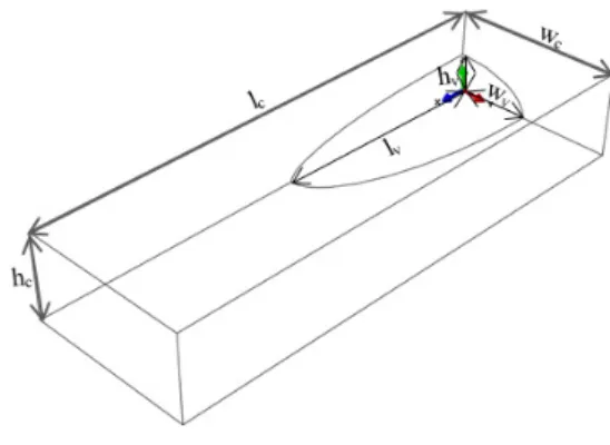
Voids are commonly interpreted as regions in the layers that are taken out and replaced by air pockets. As shown in fig.1.a.b.c that represents a microtomography of a layer, voids are mainly oriented along fibre direction and globally shaped as ellipspoid. The voids can thus be represented by ellipsoid limited volumes and the geometric of the voids can be defined by three dimensional parameters: length, width, and height. We use the same finite element analysis approach as those presented below to calculate elastic constant of laminate with voids. One eighth of a representative volume element containing void is shown in [figure 5].Given a set of void characteristics (void content and two aspect ratios), the dimensions of the RVE is fully defined. The ratios between the three dimensions of the RVE should be equal to the ratios between the three dimensions of the given void [5]. c c v v w c c v v l h w h w R w l w l R = = ; = = (5)
Where lv, wv, hv and lc, wc, hc are the length, width, height of the void and the RVE, respectively. lc
is the direction of the fibre. hc is fixed equal to the thickness of the tows because the void content is
calculated at this scale. The analysis is carried out on a composite within 60% of fibre. The material properties used in the calculations and listed in the table 2 are deduced from results obtained in section 3. 40 45 50 55 60 65 70 75 80 1.6 1.8 2 2.2 2.4 2.6 2.8 3 3.2 3.4 3.6 Gyz
Fibre volume fraction (%)
G y z (G p a ) Numerical data H-T 40 45 50 55 60 65 70 75 80 2 2.5 3 3.5 4 4.5 5 Gxy-Gxz
Fibre volume fraction (%)
G x y -G x z (G p a ) Numerical data H-T 40 45 50 55 60 65 70 75 80 0.22 0.23 0.24 0.25 0.26 0.27 0.28 0.29 0.3 vxy
Fibre volume fraction (%)
v x y Numerical data H-T 40 45 50 55 60 65 70 75 80 0.32 0.34 0.36 0.38 0.4 0.42 0.44 0.46 vyz
Fibre volume fraction (%)
v
y
z
[
Gpa]
E11 E22
[
Gpa]
G12[
Gpa]
G23[
Gpa]
νf12 νf23property
Composite 139 7.1 3.1 2.2 0.25 0.4
Table 2: Elastic properties of carbon /epoxy composites (ff=60%)
The first analysis is dedicated only to the effect of void content, when the voids have a spherical shape Rl= Rw=1.The void content varies from 0 to 10% in accordance with the case of filament
wound structures [1]. The prediction of normalized modulus reductions are shown in [figure 8].
The second analysis is dedicated to examine the effects of void microstructures and geometry, on the elastic response of composite laminates. General trends can be noticed, all curves are a similar shape that can be described as nearly linear. The analyses predict that the reduction of all modulus increases with void content [figure 6]. and the presence of voids has much larger impact on the longitudinal moduli properties compared with the transvers moduli and shear modulus (the case of spherical void). The shape of voids has also different and severe impact on the effective moduli [figure 7]. Long voids reduce significantly the out-of-plane shear modulus, but cause a little effect on the in-plane properties.
Figure 5: Representative Volume used in Finite Element Analysis to study the effect of void.
Figure 6: Normalized modulus reductions vs void content Rlw= Rwh=1
0 1 2 3 4 5 6 7 8 9 10 0 5 10 15 20 25 Void content(%) N o rm a liz e d M o d u lu s r e d u c ti o n (% ) Ex Ey-Ez Gyz Gxy-Gxz
a) b)
c) d)
Figure 7: the influence of aspect ratio on elastic moduli predicted by FEA
a) Ex b) Ey-Ez c) Gyz d) Gxy-Gxz
5. Conclusion
The objectives of this work were realised on two stages. The first one is to predict the micromechanical stiffness of fibre and matrix composite using the finite element analysis. The results are compared with the analytical model and difference can be observed which can get to 20%, hence the use of the finite element analysis is relevant to better predict the mechanical properties. The second stage concerns the parametric study which is done to reveal the effects of the fibre content and geometry of voids on the mechanical properties of the composite. A first insight shows that the modulus can be reduced significantly on the presence of the voids and this reduction depends strongly to the geometry and the content of voids. In the future the objective is to complete the parametric study and to develop a micromechanical model which depends to all parameters as content, geometry and density of voids.
References
[1] A. PILATO. Thesis Caractérisation des structures composites bobinées épaisses, application à l’étude du comportement de réservoirs de stockage d’hydrogène, University of Bordeaux 1, 2011. [2] N.Perry et al, A Thick composite design for hydrogen vessels: A contribution to composite design method. CIRP Ann Manuf Technol.;62:139–142. 2013.
[3] Z. Hashin and B.W Rosen. The elastic moduli of fibre-reinforced materials. ASME J. Appl. Me&, 31, 223-32, 1964. 1 1.5 2 2.5 3 3.5 4 4.5 5 8 9 10 11 12 13 14 Rl(Rw=1) N o rm a liz e d E x r e d u c ti o n (% ) 1 1.5 2 2.5 3 3.5 4 4.5 5 8.5 9 9.5 10 10.5 11 Rl(Rw=1) N o rm a liz e d E y -E z r e d u c ti o n (% ) 1 1.5 2 2.5 3 3.5 4 4.5 5 9.5 10 10.5 11 11.5 12 12.5 Rl(Rw=1) N o rm a liz e d G y z r e d u c ti o n (% ) 1 1.5 2 2.5 3 3.5 4 4.5 5 8 8.2 8.4 8.6 8.8 9 9.2 9.4 9.6 9.8 10 Rl(Rw=1) N o rm a liz e d G x y -G x z r e d u c ti o n (% )
[4] J. M. Whitney and M. B. Riley. Elastic properties of fibre reinforced composite materials. AlAA
J., 4, 1537-42, 1966.
[5] H. Huang. Effects of void geometry on elastic properties of unidirectional fibre reinforced composites, Composites Science and Technology, 65 1964–1981, 2005.
[6] C. T. Sun and R.S. Vaidya. Prediction of composite properties from a representative volume element, Composites Science and Technology 56, pp.171-179, 1996.
[7] R. Maligno. Thesis Finite Element Investigations on the Microstructure of Composite Materials [8] S. Li, General unit cell for micromechanical analyses of unidirectional composites, Composites
Part-A 32, PP. 815-816, 2000.
[9] L. Warnet & R. Akkerman.Composites Course, University of Twente, Eng. & Tech,2009. [10] Gibson's. Principle of Composite Material Mechanics.McGraw-Hill,New York, 1994. [11] D. Hull and T.W. Clyne. An Introduction to Composite Materials, Cambridge University
Press, Cambridge, 1996.
[12] M.W. Hyer and A.M. Waas. Micromechanics of Linear Elastic Continuous Fiber Composites.
![Figure 1: Void's characterisation :a) Microtomography b) image analysis c) Section parallel to fibre direction d) Section perpendicular to fibre direction [1]](https://thumb-eu.123doks.com/thumbv2/123doknet/7433019.219977/3.892.105.790.409.575/characterisation-microtomography-analysis-section-parallel-direction-perpendicular-direction.webp)

![Figure 3: ¼ RVE of the hexagonal array packing used in finite element analysis Carbon [ ] 2301 GpaEf [ ]142GpaEf [ ]912GpaGf [ ]423GpaGf 2.0 12νf 25.023νf Epoxy [ ] 3 GpaEm − [ ]1.1GpaGm − 35.0νm −](https://thumb-eu.123doks.com/thumbv2/123doknet/7433019.219977/5.892.82.816.168.306/figure-hexagonal-packing-finite-element-analysis-carbon-gpaef.webp)