Science Arts & Métiers (SAM)
is an open access repository that collects the work of Arts et Métiers Institute of
Technology researchers and makes it freely available over the web where possible.
This is an author-deposited version published in: https://sam.ensam.eu Handle ID: .http://hdl.handle.net/10985/6916
To cite this version :
Imade KOUTIRI, Daniel BELLETT, Franck MOREL, Louis AUGUSTINS, Jérôme ADRIEN - High cycle fatigue damage mechanisms in cast aluminium subject to complex loads - International Journal of Fatigue - Vol. 47, p.44-57 - 2013
Any correspondence concerning this service should be sent to the repository Administrator : [email protected]
High cycle fatigue damage mechanisms in cast aluminium
subject to complex loads
Imade Koutiria, Daniel Belletta, , , Franck Morela, Louis Augustinsb, Jérôme Adrienc
a Arts et Métiers ParisTech, CER Angers – Laboratoire LAMPA – 2 Bd du Ronceray, 49035 Angers Cedex 1, France b PSA Peugeot Citroën, Route de Gisy, 78943 Vlizy-Villacoublay Cedex, France
c INSA de LYON – Laboratoire MATEIS, UMR CNRS 5510, 25 Avenue Jean Capelle, 69621 Villeurbanne Cedex, France
Abstract
This article is dedicated to the high cycle fatigue behaviour of cast hypo-eutectic Al–Si alloys. In particular, the AlSi7Cu05Mg03 alloy is investigated. It presents the results of a vast experimental campaign undertaken to investigate the fatigue behaviour, and more specifically the fatigue damage mechanisms observed under complex loading conditions: plane bending with different load ratios, fully reversed torsion and equibiaxial bending with a load ratio of R = 0.1. A specific test set-up has been designed to create an equibiaxial stress state using disk shaped specimens. A tomographic analysis is also presented with the aim of characterising the micro-shrinkage pore population of the material. It is shown that two distinct and coexisting fatigue damage mechanisms occur in this material, depending on the presence of different microstructural heterogeneities (i.e. micro-shrinkage pores, Silicon particles in the eutectic zones, Fe-rich intermetallic phases, etc.). Furthermore, it is concluded that the effect of an equibiaxial tensile stress state is not detrimental in terms of high cycle fatigue. It is also shown that the Dang Van criterion is not able to simultaneously predict the multiaxial effect (i.e. torsion and equibiaxial tension) and the mean stress effect for this material.
Highlights
► A large number of experimental fatigue data for AlSi7Cu05Mg03 are presented. ► An innovative experimental setup is used (axisymmetrical bending). ► A tomography analysis of the material is presented. ► The effect of an equibiaxial tensile stress state is not detrimental. ► Two different coexisting fatigue damage mechanisms have been identified.
Keywords
AlSi7Cu05Mg03-T7; High cycle fatigue; Damage mechanisms; Mean stress effect; Equibiaxial loads
1. Introduction
The need to increase performance while at the same time reducing costs in the manufacturing and transportation industries leads to components that are subject to increasingly severe mechanical
loading conditions. As such, it is possible to find components submitted to cyclic stress states that have very high mean stress and a high degree of stress triaxiality. For these conditions, which can be defined as “extreme”, the fatigue damage mechanism as well as the fatigue strength are, in most cases, completely unknown. Hence, problems are encountered when designing such components, as existing fatigue criteria have difficulties predicting these loading conditions and the fatigue data necessary to identify the criteria parameters are practically non-existent.
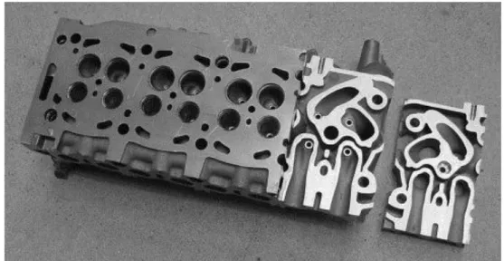
The fatigue design of cast aluminium diesel engine cylinder heads, used in the automotive industry, is an example of this type of problem. These components have a very complicated geometry due to the admission, exhaust and cooling passages and the valve control system, but are essential to the correct operation of the engine (see Fig. 1). In order to ensure that these components conform to their required specifications, numerical modelling techniques are employed [1] and [2]. The results from these simulations show that certain zones of these components are subjected to complex multiaxial cyclic stress–stain states, including high mean stress. This loading mode is the result of the superposition of residual stresses caused by the fabrication process (i.e. gravity sand casting) and the subsequent heat treatment, the thermal stresses resulting from in-service conditions, stresses due to the assembly of the engine (e.g. bolting loads) and the alternating stress due to the variation in pressure of the fluids in contact with the thin wall sections in the fatigue critical zones. Hence, the high cycle fatigue design of these components requires the use of a fatigue criterion which is adapted to the material and the specific loading conditions. The object of this work was to develop an appropriate criterion for this application. This criterion will be presented in a future publication. The present article focuses on the experimental investigation, with particular attention given to the investigation of the fatigue damage mechanisms for different loading modes occurring in the cast aluminium alloy in question.
Fig. 1. The PSA diesel engine cylinder head. The upper surface is the engine block mating surface. The right end of the cylinder head has been sectioned via a horizontal cut.
An extensive literature review has highlighted the fact that there exists a large amount of uniaxial fatigue data for this material, for example in rotating bending, plane bending or uniaxial tension– compression loading conditions [3], [4], [5], [6], [7], [8], [9], [10], [11], [12], [13] and [14]. However, this
data is often limited to load ratios of either R = −1 or R = 0.1 and very little, if any, data is available for biaxial tensile loads and torsion.
The principal aims of the work presented in this article are: (a) to investigate the effect of different loading modes (i.e. bending with different load ratios, torsion and equibiaxial bending) on the fatigue response of the cast aluminium alloy, AlSi7Cu05Mg03-T7 and (b) to highlight the role of the different microstructural heterogeneities on the fatigue damage mechanisms observed under the different loading modes.
2. Specimen extraction and the material: AlSi7Cu05Mg03-T7
2.1. Specimen extraction
Fatigue specimens were made from material taken directly from cylinder heads (see Fig. 1) manufactured by PSA for use in automotive diesel engines. The cylinder heads were gravity sand cast. During the casting process titanium and boron are added to the liquid metal in order to refine the size of the alpha-phase dendrites. Strontium is added to modify the shape of the silicon eutectic particles. The cast components are subsequently heat treated using the following procedure:
• Solution heat-treatment for 5 h at a temperature of approximately . •Water quenching at a temperature of approximately .
•Tempering at for 5 h. •Cooling in ambient air.
The resulting mechanical properties of the material are listed in Table 1. Table 1. Mechanical properties of AlSi7Cu05Mg03-T7.
0.2% Yield stress σY (MPa) Ultimate tensile strength σuts (MPa) % Elongation A%
250–260 318–330 5.0–5.7
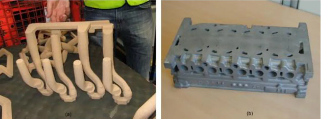
The casting of specimens using a specific “specimen shaped mould” can have the disadvantage that the material may not have the same microstructural and mechanical properties as the material resulting from the real industrial manufacturing process. It was therefore decided, in collaboration with the industrial partner, PSA, to slightly modify a limited number of cylinder heads in order to have a much larger volume of material from which fatigue specimens could be extracted. This was done by reducing the length of the inlet and exhaust cores (see Fig. 2a). The resulting modified cylinder heads have blocked inlet and exhaust passages on the engine block mating surface (see Fig. 2b). This resulted in a layer of material with a maximum thickness of approximately 8 mm, from which the specimens, described in more detail later, were extracted.
Fig. 2. (a) Modified cores used to shape the inlet and exhaust passages. (b) Cylinder head after modification.
It is of course possible that these modifications to the casting process result in changes to the material properties. In particular, the Dendrite Arm Spacing (DAS), the hardness and the size and distribution of micro-shrinkage pores may have been affected. Therefore, a detailed investigation of these properties, before and after modification of the casting process was done and very little variation of these quantities was found.
The DAS was measured in four different zones of the engine block mating surface. An average DAS of 80 ± 10 μm (based on 10 measurements per zone) was found. The average Brinell hardness (based on 20 measurements) is 104 ± 3 HB. The size of micro-shrinkage pores found in 16 different zones (of approximately 20 × 15 mm) randomly positioned on the mating surface were measured using an optical microscope and the image analysis program, Visilog. The surface area of the micro-shrinkage pores was measured to be between 6×10⁻² and . Table 2 shows the comparison of
these measurements between a modified and an unmodified cylinder head for four different locations on the mating surface.
Table 2. Comparison between the modified and unmodified cylinder heads.
Zone 1 Zone 2 Zone 3 Zone 4
Modified Un-modified Modified Un-modified Modified Un-modified Modified Un-modified DAS (μm) 78.7 80 79 71 89 73 90 77 Hardness (HB) 104 105.8 104 104 104 104 104 107 Max pore size 118.3 100 141 114 245 127 92 134 Min pore size 55.6 48.9 51 61 55 63 48 63
In addition, measurements of the pore size and distribution have been done by tomography and are discussed below.
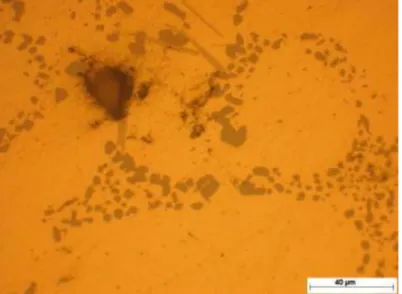
Fig. 3 shows the material microstructure created as a result of the process described above. The material is composed of alpha-phase dendrites with an average Dendrite Arm Spacing (DAS) of approximately 80 μm. The eutectic silicon particles are fine and spherical. The dark feature in Fig. 3 is a casting defect (i.e. a micro-shrinkage pore) caused by the shrinkage of the molten liquid during solidification. In a complicated gravity cast component like a cylinder head it is difficult to completely eliminate this type of defect. The presence of intermetallic phases can also be distinguished.
Fig. 3. Microstructure of the cast aluminium alloy AlSi7Cu05Mg03-T7.
In order to characterise the size and spatial distribution of the shrinkage pores in the cast aluminium alloy used in the cylinder heads, the tomography technique was used in collaboration with the MATEIS laboratory of INSA Lyon. The investigation was done using a Phoenix/X-ray v/tome/x tomography. The analysis was conducted on a specimen taken from the mating surface of a modified cylinder head. The volume of scanned material was equal to . A voxel size of was used. After post-treatment of the tomographic images it is possible to determine the size distribution of the pores as well as their sphericity, s. The determination of the sphericity is done by the marching cube method and requires knowledge of the volume, V, and the surface area, S, of each pore. The sphericity is defined by:
(1)
This parameter is equal to 1.0 for a pore that is perfectly spherical and s = 0 for a pore that is very distorted[15].
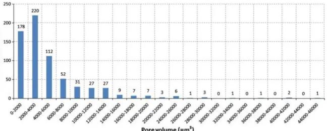
The pore size distribution, shown in Fig. 4, proves that the great majority of pores are small. In fact, the number of very large pores is quite limited. If the pores are assumed to be spherical, the maximum pore diameter would be 44 μm. However the pore geometry is not this simple, as can be seen in Fig. 5a which shows the sphericity distribution. This figure indicates that 33% of the pores have sphericities between 0.2 and 0.6.
Fig. 4. Size distribution of micro-shrinkage pores present in the scanned material.
Fig. 5. (a) Sphericity distribution of micro-shrinkage pores and (b) the position of pores with respect to X and Y axes. The Z axis corresponds to the tensile axis of the specimen. The pore positions are projected onto the XY plane.
The spatial distribution of the pores is shown in Fig. 5b which plots the position of each pore projected onto a plane perpendicular to the loading axis of the specimen. It can be seen that the pores are distributed in a quasi-homogeneous manner within the volume. No particular “clustering” of the defects can be observed.
Fig. 6a shows the pore sphericity as a function of the pore volume. This figure indicates that the sphericity of the smallest pores is highly variable, ranging between 0.3 and 1.0, while the largest pores (with volumes greater that 20,000 μm3) have a smaller sphericity range of between 0.4 and 0.6.
From Fig. 6b it can be seen that several of these large pores are positioned close to the edge of the specimen and are therefore possible fatigue crack initiation sites. Also, the spatial distribution of the largest pores is relatively homogeneous.
Fig. 6. (a) Pore sphericity as a function of volume and (b) the position of the largest pores (⩾20,000 μm3). The Z axis corresponds to the tensile axis of the specimen. The pore positions are projected onto the XY plane.
Buffière and co-workers [3] have undertaken a similar investigation of a cast aluminium alloy. The material studied by Buffière and co-workers was the A356 aluminium alloy. Different degrees of micro-shrinkage porosity were introduced by these researchers through the addition of a hydrogen/Argon gas mixture injected into the liquid metal at 820 °C. The resulting alloys, referred to as Alloys A, B and C, were cast with 2%, 7% and 10% H2 respectively, mixed with Ar and lead to different pore sizes and
forms. In this work by Buffière et al. [3], the material is solution heat treated after solidification for 10 h at and then tempered and quenched for 6 h at (corresponding to a T6 heat treatment). The average DAS of the material is 30 μm. Two geometrical parameters, the equivalent size λ (equal to the diameter of a sphere with the same volume) and the sphericity, s, were used. These authors highlight the fact that this treatment results in the existence of two distinct pore populations. The first includes the vast majority of pores and is characterised by an equivalent size of λ<50μm and a small “size/sphericity” ratio. This pore distribution is approximately equivalent for the three alloys. These are effectively micro-shrinkage pores and are due to the change in volume that occurs during the solidification process. The second pore distribution contains defects of greater size and have high “size/sphericity” ratios. Their volume fraction increases with the increasing percentage of hydrogen injected in the liquid metal. Theses defects are artificial pores that appear during solidification and have a very tortuous form.
The fact remains that the largest pores and thus the pores which are potentially the most dangerous in terms of fatigue have low sphericity values (or are very distorted). As such, it does not seem appropriate to assume that these defects have a spherical geometry. This is one of the reasons that the proposed modelling approach which will be presented in a future publication, treats micro-shrinkage casting defect as pre-existing cracks, with the aim of determining the loading conditions for which these cracks are able to overcome the microstructural barriers present in the material.
All of the fatigue tests presented below were conducted at ambient temperature and pressure in laboratory air.
2
3.1. Plane bending fatigue tests
A series of uniaxial plane bending fatigue tests were undertaken, with the aim of identifying the effect of the mean stress. Five different load ratios have been investigated:
• R = −1 (with zero mean stress, σm=0 MPa).
• R = 0.1.
• R = 0.62 (with the maximum stress slightly less than the yield stress, σmax≈σY).
• R = 0.88 (with the mean stress equal to the yield stress, σm≲σY).
• R = 0.92 (with the maximum stress slightly less than the ultimate tensile strength, σmax≲σuts).
For each load ratio, the fatigue strength at 2×10⁶ cycles was determined via the staircase method
using a minimum of 10 specimens. For the R = −1 load case a staircase with 20 specimens was done in order to estimate the associated standard deviation. All tests were done using a RUMUL Cracktronic electro-magnetic resonance fatigue testing machine. The test frequency was approximately 80 Hz. Tests were stopped when a drop in frequency of 0.1 Hz was detected. This corresponds to the presence of a fatigue crack of approximately 3 mm long.
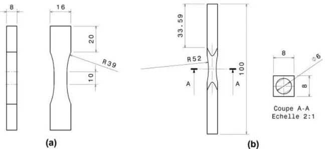
The geometry of the specimens tested in plane bending are shown in Fig. 7a.
Fig. 7. The geometry of the specimens tested in (a) plane bending and (b) torsion (dimensions in mm).
3.2. Torsional fatigue tests
Torsional fatigue tests, with zero mean stress (R = −1), were also done. The RUMUL Cracktronic machine was used with the same testing conditions as described above. The geometry of the specimens tested in fully reversed torsion are shown in Fig. 7b.
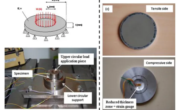
Concerning the biaxial fatigue tests, as the volume of material, available to fabricate the specimens, was relatively small it was not possible to make, for example, hollow specimens for tension/internal pressure type tests. Therefore, an axisymmetrical bending testing apparatus was developed to undertake these tests (seeFig. 8). This test setup forms the object of a French national patent submitted in May 2011 [16]. Disk shaped specimens with a reduction in thickness on the compressive side of the specimen are tested (see Fig. 8c and d). The specimens have an outside diameter of 92 mm and a thickness of 8 mm. The reduced thickness zone in the centre of the specimen has a diameter of 10 mm and a thickness of 5 mm. A radius of 30 mm is used to make the transitions between this zone and the compression side of the disk. The tests were conducted using a servo-hydraulic INSTRON 8802 fatigue testing machine. An equibiaxial stress state is obtained at the centre of the specimen. In order to verify the local strain state and to detect fatigue crack initiation, a uniaxial strain gauge was glued at the centre of the compressive side of each specimen in the flat part of the reduced thickness zone (see Fig. 8d). The minimum value of strain per cycle was recorded. The appearance of a fatigue crack on the tensile side of the specimen results in a change in the measured strain field. This method of crack detection was found to be both reliable and repeatable. For this material and experimental set-up, a change in strain of 150 micro-strain corresponds to an approximate crack length of 6 mm.
Fig. 8. (a) Schematic representation of the test; (b) the testing apparatus; (c) view from the tensile side of the specimen; and (d) view from the compressive side of the specimen.
Note that only positive load ratios can be tested using this setup, and that the equibiaxial stress state is proportional and in-phase. The equibiaxial fatigue limit at 2×10⁶ cycles has been determined for a
load ratio of R = 0.1 using the staircase method (with 9 specimens). The tests were conducted at a frequency of 20 Hz.
4. Mean stress and biaxial effects
4.1. The mean stress effect under uniaxial loading (plane bending and tension)
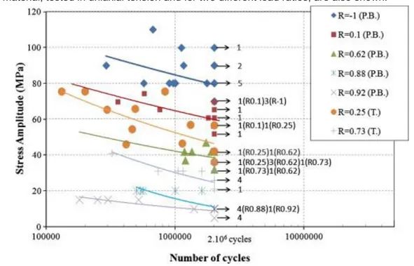
Fig. 9 shows the fatigue results obtained by the tests discussed above, presented as a Wöhler diagram, for the different load ratios tested. Note that previously unpublished results obtained for the same material, tested in uniaxial tension and for two different load ratios, are also shown.
Fig. 9. Wöhler diagram showing all the uniaxial data for the cast alloy AlSi7Cu05Mg03 (P.B. = plane bending tests and T. = tensile tests).
It is important to note that even for the high load ratios (R = 0.88 and 0.92) where the maximum stress is close to the ultimate tensile strength a fatigue limit at 2×10⁶ cycles exists.
Table 3 summarises the uniaxial results in terms of the fatigue limits at 2×10⁶ cycles for 50%
probability of failure. The scatter decreases with increasing mean stress.
Table 3. Experimental values for the fatigue strength of the cast aluminium AlSi7Cu05Mg03 at 2×10⁶ cycles for different uniaxial loading conditions.
σmean (MPa) σamp (MPa) Load ratio Standard deviation (MPa)
Plane bending 0 83 −1 18 77 63 0.1 – 196 45 0.62 – 251 15 0.88 – 284 12 0.92 – Uniaxial tension 83 51 0.25 – 172 26 0.73 –
4.2. The torsional fatigue behaviour
The staircase method was used to determine the fully reversed torsional fatigue limit of the cast aluminium alloy under investigation. A total of 19 specimens were tested. The average fatigue limit and standard deviation at 2×10⁶ cycles are shown in Table 4.
Table 4. Torsional fatigue strengths for cast aluminium AlSi7Cu05Mg03 at 2×10⁶ cycles. Torsion
τmean (MPa) τamp (MPa) Load ratio Standard deviation (MPa)
0 92 −1 14
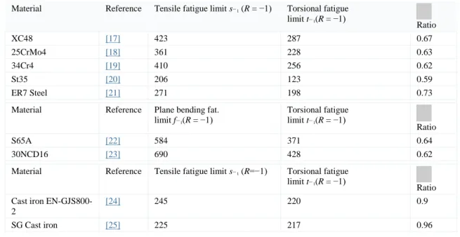
As previously discussed the plane bending fatigue limit of the AlSi7Cu05Mg03 cast alloy for R = −1 is 83 MPa. Hence, the mean fatigue limit of the material in torsion is greater than that obtained in plane bending. This is perhaps a surprising result. However, an investigation of fatigue data taken from the literature, summarised in Table 5, highlights the fact that metallic materials can be divided into categories, depending on the ratio of their torsional fatigue limit, t−1, to their uniaxial fatigue limit (s−1 in
tension and f−1 in plane bending for R = −1).
Table 5. Torsional/uniaxial fatigue ratios for different materials taken from the literature. Material Reference Tensile fatigue limit s−1 (R = −1) Torsional fatigue
limit t−1(R = −1) Ratio XC48 [17] 423 287 0.67 25CrMo4 [18] 361 228 0.63 34Cr4 [19] 410 256 0.62 St35 [20] 206 123 0.59 ER7 Steel [21] 271 198 0.73
Material Reference Plane bending fat. limit f−1(R = −1) Torsional fatigue limit t−1(R = −1) Ratio S65A [22] 584 371 0.64 30NCD16 [23] 690 428 0.62
Material Reference Tensile fatigue limit s−1 (R=−1) Torsional fatigue limit t−1(R = −1)
Ratio Cast iron
EN-GJS800-2
[24] 245 220 0.9
SG Cast iron [25] 225 217 0.96
The first category of materials can be characterised by a fatigue limit ratio of approximately: (2)
Many steels belong to this category.
For the second category, the ratio is closer to 1 and this category includes SG cast iron. Like the cast aluminium alloy studied here, SG cast iron is a material for which the fatigue strength and crack initiation mechanisms are controlled by the presence of pores.
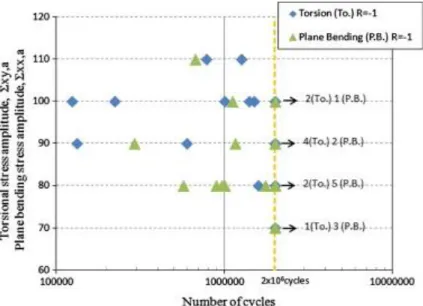
For the AlSi7Cu05Mg03 aluminium alloy, the relationship between the torsional fatigue limit and the plane bending limit is 1.1. If all of the torsional and plane bending fatigue data are plotted on the same Wöhler curve (see Fig. 10), the difference between these two loading modes is not significant.
Fig. 10. Wöhler diagram for AlSi7Cu05Mg03 showing torsional and plane bending fatigue data.
The specimens loaded in torsion and plane bending were extracted randomly from the mating surface of the modified cylinder heads. When subjected to these different loading conditions the volumes of highly stressed material in the specimens is different. For the torsion case, the toroidal geometry of the specimen may partly explain the results. The probability of encountering a defect is much lower as the highly stressed volume is smaller. Taking into account the stress gradients and the shape of the specimens, it is estimated that the volume of material loaded between 90% and 100% of the maximum stress is 128 mm3 for the plane bending specimens and 24 mm3 for the torsional specimens.
In conclusion, the higher value of the fatigue limit in torsion compared to bending plane is surprising, however, it is probably due to the test conditions (loading + specimen geometry). The fact remains that the fatigue behaviour of this material can be characterised as “brittle”.
3
4.3. The effect of an equibiaxial stress state
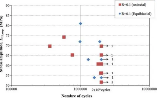
Fig. 11 shows the comparison between the uniaxial and equibiaxial fatigue test results for a load ratio ofR = 0.1.
Fig. 11. Wöhler diagram for AlSi7Cu05Mg03 (R = 0.1, plane bending: uniaxial stress state and R = 0.1, axisymmetrical bending: equibiaxial stress state).
This diagram highlights the fact that the scatter for both loading types is basically the same, and more surprisingly it shows that there is very little difference between the average fatigue limits at 2× 10⁶ cycles. This implies that an equibiaxial loading condition does not result in greater fatigue damage
than the uniaxial case (at least for this material).
5. Fatigue damage mechanisms
5.1. Uniaxial loads
Much research has been reported in the scientific literature concerning the fatigue initiation mechanisms in cast aluminium alloys, which is generally related to uniaxial loads at low R-ratios (i.e. R = −1 or 0.1) [3], [4],[5], [6], [7], [8], [9], [10], [11], [12], [13] and [14]. The porosity, the secondary dendrite arm spacing, the Al-matrix, Si-particles, and Fe-rich intermetallic phases have been experimentally identified as the major factors affecting the alloys resistance to fatigue. This work shows that due to the different microstructural heterogeneities present in the material, fatigue crack initiation sites can be varied. However, when micro-shrinkage pores are present they play the fundamental role in controlling fatigue behaviour. Their size, position, distribution, etc., have a large impact on the fatigue resistance of the material [3], [4], [5], [6], [7],[8] and [9]. When specific treatments, such as HIP (Hot Isostatic Pressing), are used to obtain a microstructure which is practically free of micro-shrinkage pores, crack initiation occurs at other microstructural heterogeneities, such as oxide inclusions, silicon eutectic particles or intermetallic phases[10], [11], [12] and [13] or takes place in the ductile primary α-Al phase [14].
In this work, numerous fatigue damage observations have been undertaken using specimens made from material extracted from cylinder heads cast by PSA. Both surface observations (using an optical
microscope during cycling) and observations of the fatigue failure surfaces (using a Scanning Electron Microscope, SEM) have been done. These observations show that for plane bending and uniaxial tensile loads with an R-ratio of R = −1, initiation of the fatigue crack, resulting in final failure of the specimens, almost always occurs at a micro-shrinkage pore (see Fig. 12).
Fig. 12. Fatigue crack initiation from a micro-shrinkage pore in AlSi7Cu05Mg03, loaded uniaxially with an R -ratio ofR = −1. (a) Surface observation; (b) an SEM image of a failure surface.
However, it is very important to note, that in the same specimens, micro-cracks are observed to initiate at Silicon particles in the eutectic zones or at intermetallic phases (see Fig. 13a). For the material and loading conditions in question, this type of damage is not generally responsible for the final failure of the specimen, but it does exist.
Fig. 13. (a) Fatigue crack initiation at Si-particles in the eutectic zones. (b) Initiation from a micro-shrinkage pore for which the crack propagation has been stopped by the presence of microstructural barriers (intermetallic phases) in AlSi7Cu05Mg03 for uniaxial loads with an R-ratio of R = −1.
It is therefore concluded that fatigue damage in this material is controlled by two different fatigue crack initiation mechanisms: One mechanism is associated with relatively large micro-shrinkage pores and the other is controlled by much smaller microstructural heterogeneities or the material matrix.
It is proposed that the first mechanism is basically a problem of crack propagation, or more precisely, of crack arrest or non-propagation. That is, fatigue cracks initiate very quickly at micro-shrinkage pores and the fatigue strength is then controlled by the ability of the microstructure to prevent the propagation of these cracks (see Fig. 13b). In a future publication, a fracture mechanics approach is proposed to describe this damage mechanism.
For the second mechanism, in which fatigue damage occurs at a smaller scale, it is assumed that crack initiation is controlled by localised plasticity, related to the micro-structural heterogeneities in question, or simply the material matrix. A multi-scale fatigue criterion, based on the concept of elastic shakedown, will be used to describe this fatigue damage mechanism in a future publication.
5.2. Torsion loads
In order to characterise the initiation and propagation mechanisms associated with torsional loads, cyclic tests were interrupted after a certain number of cycles and the specimen is examined for fatigue damage. The applied shear stress amplitude at R = −1 was equal to τxy=80 MPa and the test
frequency was 50 Hz.
After 150,000 cycles, initial observations showed cracks that had initiated at Si-particles of the eutectic zones. Fig. 14 shows an example of a crack that has initiated in the eutectic zone which is approximately 200 μm long. This crack has clearly initiated on the plane of maximum shear stress. Its propagation is clearly influenced by the microstructure as its preferential propagation path is in the eutectic zone. This crack also branches at 90° onto another plane of maximum shear stress, while remaining in the eutectic zone.
Fig. 14. Crack initiation, due to torsional loads, in the eutectic zone (150,000 cycles, τamp=80 MPa, R = −1).
Observations during the second interruption at 250,000 cycles showed that this crack had not propagated any further. However, several other crack initiation sites were detected where surface pores, of size less than 100 μm, gave rise to fatigue cracks.
At 400,000 cycles, the first crack that was detected was still non-propagating and remained so until rupture of the specimen. The cracks that appeared at the surface pores also became non-propagating. The final failure of the specimen occurred at 1.2×10⁶ cycles due to a crack that was not observed
during the previous interruptions. The initiation site of this crack was a surface pore that was visible with the naked eye. The direction of crack propagation was perpendicular to the axis of the specimen, in a plane of maximum shear stress (mode III).
5.3. Equibiaxial loads
The initiation of fatigue cracks at microstructural heterogeneities and their subsequent propagation due to an equibiaxial stress state has been investigated via surface observations during interrupted tests and on failed specimens.
Surface observations on non-failed specimens subjected to 2×10⁶ cycles with a load ratio of R = 0.1
have shown that the same two fatigue initiation mechanisms, observed in the uniaxial case, are present. Certain cracks grow from micro-shrinkage pores positioned on the surface of the specimens (Fig. 15) other fatigue cracks initiate at silicon particles (or intermetallic phases) in the eutectic zone of the microstructure (Fig. 16). However, unlike the uniaxial loading case, no preferential crack growth direction can be discerned. Several cracks can grow in different directions from the same pore (Fig. 15c) and cracks can be observed to branch at all crack sizes (Fig. 17).
Fig. 16. Crack initiation at silicon particles or intermetallics in the eutectic zone under equibiaxial tensile loads with a load ratio of R = 0.1 in AlSi7Cu05Mg03.
Fig. 17. Evolution of the propagation of a fatigue crack that initiated at a surface pore under an equibiaxial loading condition at R = 0.1.
Theses observations have shown that crack initiation principally occurs at micro-shrinkage pores however sometimes cracks initiate at silicon particles or intermetallic phases. An investigation of the evolution of one of these cracks, loaded at the same R-ratio of 0.1, has been done. The results are summarised in Fig. 17. It can be seen that after 2,002,000 cycles a crack has initiated at a
micro-shrinkage pore, with a size of less than 50 μm and that the crack has propagated through an α phase dendrite to reach another pore, so that the crack length is approximately 300 μm. The propagation is approximately along a straight line during 70,000 cycles. After 2,287,000 cycles the crack is seen to branch twice. Once close to the top of the crack and once close to the bottom. The length of the crack is slightly greater than 1 mm. At 2,487,000 cycles the crack size is greater than 3 mm.
The observed crack initiation sites are almost exclusively associated with micro-shrinkage pores. These pores are of variable size but they are relatively small (i.e. less than 100 μm). The failure surfaces around these pores are similar to these observed in uniaxial case for this type of cast material (Fig. 12b).
6. Analysis
The microstructural heterogeneities present in this cast aluminium alloy result in different crack initiation mechanisms and fatigue behaviour for different applied loading conditions.
For torsional loads, it is observed that cracks propagate in mode III and do not tend to branch at any crack length. When the torsional fatigue limit (in terms of shear stress) is approximately equal to the uniaxial fatigue limit (in terms of principal stress) it could be expected that the fatigue behaviour should be dominated by the maximum principal stress. However, the crack path observed in torsion is directed along the direction of maximum shear stress (see Fig. 14). This appear to be a contradiction, however similar observations have been made for other materials in which macroscopic shear cracks can be formed in high cycle fatigue. This has been shown by Pinna and Doquet for M250 maraging steel [26] and by Socie for Inconel 718 [27]. Hence, an independent mode II or III fatigue crack development is possible, provided the range of the stress intensity factor lies above a given threshold. A tentative explanation for the crack paths observed in the cast aluminum alloy loaded in torsion can be based on the idea of a competition between mode I and mode II crack kinetics, as discussed by Pinna and Doquet [26]. For the load levels applied in the present work, it can be assumed that the mode I kinetics are slower than in mode II for the complete K range. This can explain why cracks both initiate and propagate in a shear mode up until failure under these conditions and why unlike most metallic materials there is no branching from the planes of maximum shear stress to the plane of the maximum normal stress.
A common point between the maraging steel studied by Pinna and Doquet [26] and the cast aluminium alloy studied here is that the macroscopic fatigue behaviour of both materials can be classified as “brittle” (i.e.t−1/s−1≈1). For other materials not demonstrating this brittle fatigue behaviour,
crack initiation under torsional loads occurs in the planes of maximum shear stress (i.e. 0° and 90° to the specimen axis) and then branch to the planes of maximum principal stress, orientated at ±45° to the specimen axis (see Fig. 18). This has been observed for C35 steel by Flacelière and Morel [28] and for ER7 steel by Benabes [21].
Fig. 18. Orientation of macro-cracks on the surface of a specimen loaded in torsion (a) for C35 Steel [28] and b) for ER7 Steel [21].
From the tests conducted on the disk shaped specimen, leading to an equibiaxial stress state, it can be concluded that the cast aluminium material is not sensitive to the biaxiality in the high cycle fatigue regime. The biaxial results are effectively equivalent to those obtained in plane bending. This tendency was also observed by Poncelet et al. [29] concerning the fatigue behaviour of austenitic stainless steel 304L. Tests undertaken by these authors using a triaxial machine resulted in the conclusion that equibiaxial tensile loads are not detrimental compared with uniaxial fatigue. The results for the equibiaxial loading condition at R = −1 are very close to those obtained under imposed stress, uniaxial loading conditions. The authors highlight the fact that this result should be viewed with caution given the small number of tests and the scatter encountered. However, the tests conduced in the present work permit the confirmation of this tendency. Another conclusion made by these authors is the penalizing effect of the mean stress, which they highlight by comparing either the equibiaxial tests at R = 0.1 and R = −1, or uniaxial tests with different mean stress (Fmean = 38, 19 and 0 kN).
As a result of this work it is clear that the effect of an equibiaxial stress state is not harmful, in terms of high cycle fatigue. This is contrary to many preconceived ideas and is also contrary to the predictions of most multiaxial fatigue criteria.
The many observations conducted under this loading mode have highlighted the fact that the crack initiation and propagation mechanisms are similar to those observed under uniaxial loads. Crack initiation in the eutectic zones and crack growth for micro-shrinkage pores are observed, however it appears that the shrinkage pores are more often the origin of the principal crack or the crack leading to final failure. The only real difference between the uniaxial and biaxial loading modes is the orientation of the micro and macro-cracks. For plane bending, the cracks are principally orientated perpendicularly to the loading direction, whereas under equibiaxial loads no privileged crack growth direction is observed and cracks often branch.
Among the many multiaxial fatigue criteria found in the literature, certain, like the Dang Van criterion [30],[31] and [32], which will be discussed in the following, are based on the concept of elastic shakedown. More exactly, they assume that the fatigue limit occurs when the component or structure
tends to an elastic shakedown state, at all scales. In order to verify this hypothesis (at least at the macroscopic scale) for cyclic loads at high mean stress, tests were undertaken by Bellett and Morel [33] using the same cast aluminium studied here at R≈0.8. A typical result is presented in Fig. 19 which shows two stress–strain curves measured during the test. Fig. 19a shows the stress–strain behaviour of the specimen after 2×10⁶ cycles for a load level slightly below the fatigue limit. It can be
seen that a state of elastic shakedown is achieved. Fig. 19b shows a specimen loaded slightly above the fatigue limit. A cyclic ratcheting effect can be seen to lead to the final failure of the specimen at 1.15×10⁶ cycles. These observations were repeatable and seem to validate the hypothesis of elastic
shakedown, at the macroscopic scale, when the material is loaded with a high mean stress.
Fig. 19. Stress–strain curves measured during cyclic tests with high mean stress at R≈0.8. (a) A specimen that has not failed at 2×10⁶ cycles. The specimen has achieved a state of elastic shakedown. (b) A specimen loaded at slightly higher stress amplitude that failed at 1.15×10⁶ cycles showing the phenomena of cyclic ratcheting [33].
As the condition of elastic shakedown has been experimentally validated, in the following all the fatigue data obtained for the cast aluminium material is plotted in the Dang Van diagram in order to test the capacity of the criterion to predict the trends observed for the different loading modes (see Fig. 20). The Dang Van criterion is based on a two scale approach [30], [31] and [32] and the two mechanical parameters used are the mesoscopic resolved shear stress, obtained in the elastic shakedown state τ and the hydrostatic stress σH. The criterion is expressed as a linear combination of
the two parameters:
(3) τ+ασH⩽β
where τ and σH are both functions of time. In the criterion plane, the loading path changes with the
mean stress level and the stress state. All of the loading conditions, previously discussed, lead to proportional load paths. The uniaxial (i.e. bending and tension), the torsional and the equibiaxial load paths are shown in Fig. 20. The uniaxial loads with different mean stress levels have the same load path shape but are horizontally translated to the right as the mean stress level increases. The torsional path is vertical and centred at σH=0 while the equibiaxial path has a lower path slope due the higher
hydrostatic stress inherent to this loading condition. The most critical points are the ones close to the Dang Van criterion threshold line defined by the slope α and the y-axis intercept of τ=β. The two
coefficients α and β are identified by means of two fatigue limits. In most cases, the torsional and uniaxial (tensile or bending) fatigue limits are used.
Fig. 20. Dang Van diagram showing the loading paths obtained for torsion (R = −1), plane bending with different R-ratios and axisymmetrical bending (R = 0.1) loads. The Dang Van criterion is also shown (i.e. the solid black line) and has been identified using the fully reversed torsional and plane bending fatigue limits. If the criterion is capable of perfectly predicting the different loading modes, the most critical points of the different loading paths, should fall on the same line (with a negative gradient). It is obvious from Fig. 20 that this is not the case.
By considering the loading paths for fully reversed torsion and plane bending with different load ratios, it can be concluded that the mean stress effect under uniaxial loading cannot be modelled, for this cast aluminium material and this identification procedure, by the Dang Van criterion.
Another way to identify the criterion coefficients would be to use only the uniaxial results with different R-ratios. The deduced slope (i.e. coefficient α) would be much lower but the mean stress effect for uniaxial loads would be correctly predicted since the critical points of the uniaxial paths fall roughly on the same line. However, if this identification procedure is used, the predicted torsional fatigue limit is too low compared to the experimental one.
Concerning the equibiaxial tensile loading condition, it can also be seen that the effect of the biaxiality does not result in a reduction of the fatigue strength. Indeed, the use of the hydrostatic stress seems to result in an overestimation of the effect of the biaxiality.
The totality of the experimental results obtained for the AlSi7Cu05Mg03 alloy, which has a brittle fatigue behaviour, highlights without ambiguity that a criterion that uses the maximum hydrostatic stress as a mechanical parameter will not be capable of taking into account the different loading modes investigated here.
7. Conclusion
The principal objective of this work was to better understand the HCF behaviour of the aluminium alloy AlSiMg05Cu03-T7 under various uniaxial and multiaxial loading modes: plane bending with different
load ratios, fully reversed torsion and equibiaxial bending with a load ratio of R = 0. A specific test set-up has been designed to create an equibiaxial stress state using disk shaped specimens.
All tests were conducted on specimens extracted directly from cylinder heads, manufactured by PSA using the real industrial casting process. However, the geometry of the components was slightly modified to allow the extraction of fatigue specimens.
It should be noted that in this work the fatigue strength has been investigated at 2 × 10⁶ cycles and
that a diesel engine cylinder head would be expected to have a fatigue life in the giga-cycle domain. This could have important consequences in terms of the fatigue damage mechanisms, especially as it is generally accepted that the fatigue strength of aluminium alloys continues to decrease in the this domain. However, given the limitation of the available testing equipment (especially those in which it is possible to apply multiaxial loads) and in agreement with PSA (Peugeot Citron) the scope of this work was limited to 2 million cycles.
A X-ray tomography analysis of the material extracted from the cylinder heads was used to characterise the size, the form and the spatial distribution of the casting defects (i.e. shrinkage pores) present in the material. This analysis indicates that it is not reasonable to use a hemisphere to model the pore geometry, as the largest (and probably the most dangerous) pores have a very distorted shape.
Based on the vast experimental campaign undertaken by the authors, it has been shown that the experimental scatter drops significantly as the mean stress increases and that two coexisting damage mechanisms occur in this material.
Under uniaxial and biaxial tensile loading modes, initiation of the fatigue crack, resulting in final failure of the specimens, almost always occur at a micro-shrinkage pore. It is very important to note however, that in the same specimens, micro-cracks are observed to initiate at silicon particles in the eutectic zones or at intermetallic phases. The only real difference between the uniaxial and the biaxial loading modes is the orientation of the micro and macro-cracks. For plane bending, the cracks are mainly orientated perpendicular to the loading direction, whereas under equibiaxial loads no privileged crack growth direction is observed and cracks often branch. It is also observed that the fatigue limits for these two loading modes are very close. Implying that there is no detrimental effect of the biaxiality on the fatigue strength.
Under fully reversed torsional loads, the fatigue limit is very close to the plane bending fatigue limit. This is characteristic of a quasi-brittle behaviour. Moreover, after initiation, torsion cracks tend to propagate on a plane of maximum shear stress (mode III) until failure of the specimens.
Finally, it is shown that the Dang Van criterion is not able to simultaneously predict the multiaxial effect (torsion and equibiaxial tension) and the mean stress effect for this cast aluminium alloy.
In a future publication a probabilistic high cycle fatigue model, adapted to this cast aluminium alloys, will be presented. This model uses a weakest link concept to model the competition between the two experimentally observed mechanisms. The approach leads naturally to a probabilistic Kitagawa type
diagram, which in this case explains the relationship between the fatigue behaviour of the material and the different casting processes (i.e. gravity casting and HIP). It will be shown that the proposed model is capable of reproducing the experimentally observed tendencies, reported in this article, with respect to both the mean stress effect and the loading mode (torsion, uniaxial tension and equibiaxial tension).
Acknowledgments
This work was undertaken in partnership with PSA Peugeot Citroën and was financially supported by the French region, Pays de la Loire.
References
[1] F. Comte, N. Maclan, N. Morin, H. Maitournam, Z. Moumni
Prise en compte des contrainte residuelles de traitement thermique dans la prediction de la tenue en service des culasses en aluminium
Proceedings of 17eme Congrs Francais de Mecanique, Troyes, France, 6 (3) (2005), pp. 343–348 [in French]
[2] F. Comte, T.M.L. Nguyen-Tajan, N. Morin, H. Maitournam, Z. Moumni
Thermal treatment residual stresses and high cycle fatigue of an aluminum alloy cylinder head
Mecanique Indust, 6 (3) (2005), pp. 343–348
[3] J.Y. Buffière, S. Savelli, P.H. Jouneau, E. Maire, R. Fougères
Experimental study of porosity and its relation to fatigue mechanisms of model Al–Si7–Mg0.3 cast AL alloy
Mater Sci Eng A, 316 (2001), pp. 115–126
[4] X. Zhu, J.Z. Yi, J.W. Jones, J.E. Allison
A probabilistic model of fatigue strength controlled by porosity population in a 319-type cast aluminum alloy: Part I. Model Development
Metall Mater Trans A, 38 (5) (2007), pp. 1111–1122
[5] B. Zhang, W. Chen, D.R. Poirier
Effect of solidification cooling rate on the fatigue life of A356.2-T6 cast aluminium alloy
Fatigue Fract Eng Mater Struct, 23 (5) (2000), pp. 417–423
[6] Q. G Wang, D. Apelian, D.A. Lados
Fatigue behavior of A356-T6 aluminum cast alloys. Part I. Effect of casting defects
J Light Met, 1 (1) (2001), pp. 73–84
[7] J. Linder, M. Axelsson, H. Nilsson
Int J Fatigue, 28 (2006), pp. 1752–1758
[8] B. Skallerud, T. Iveland, G. Harkegard
Fatigue life assessment of aluminum alloys with casting defects
Eng Fract Mech, 44 (6) (1993), pp. 857–874
[9] H. Mayer, M. Papakyriacou, B. Zettl, S.E. Stanzl-Tschegg
Influence of porosity on the fatigue limit of die cast magnesium and aluminium alloys
Int J Fatigue, 25 (2003), pp. 245–256
[10] Y.X. Gao, J.Z. Yi, P.D. Lee, T.C. Lindley
A micro cell model of the effect of the microstructure and defects on fatigue resistance in cast aluminum alloys
Acta Mater, 52 (2004), pp. 5435–5449
[11] D.L. Mc Dowell, K. Gall, M.F. Horstemeyer, J. Fan Microstructure-based fatigue modeling of cast A356-T6 alloy
Eng Fract Mech, 70 (2003), pp. 49–80
[12] Q.G. Wang, D. Apelian, D.A. Lados
Fatigue behavior of A356-T6 aluminum cast alloys. Part II. Effect of microstructural constituents
J Light Met, 1 (2001), pp. 85–97
[13] K. Gall, N. Yang, M. Horstemeyer, D.L. McDowell, J. Fan
The influence of modified intermetallics and Si particles on fatigue crack paths in a cast A356 Al alloy
Fatigue Fract Eng Mater Struct, 23 (2000), pp. 159–172
[14] M. Brochu, Y. Verreman, F. Ajersch, D. Bouchard
High cycle fatigue strength of permanent mold and rheocast aluminium 357 alloy
Int J Fatigue, 32 (8) (2010), pp. 1233–1242
[15]Babout L. Etude par tomographie X et modelisation de lendommagement de materiaux metalliques.
PhD thesis, 2005, INSA Lyon, France [in French].
[16]Duparque C, Augustins L, Morel F, Bellett D. Machine d’essai en fatigue biaxiale disposant d’une
eprouvette, French Patent, submitted 17 May 2011, n de demande 1154287, n de soumission 1000112324.
[17]Simburger A. Festigkeitsverhalten zher werkstoffe bei einer mehrachsigen phasenverschobenen
schwingbeanspruchung mit krperfesten und vernderlichen hautspannunggsrichtungen L.B.F., Darmstadt, Bericht, Nr.FB-121; 1975. 247p.
[18]Mielke S. Festigkeitsverhalten metallischer werkstoffe unter zweiachsiger schwingender
beanspruchung mit verschiedenen spannungszeitverlufen Diss. TH Aachen; 1980. 89p.
[19] R. Hendenreich, I. Richter, H. Zenner
Konstruktion, 36 (1984), pp. 99–104
[20] L. Issler
Festigkeitsverhalten metallischer werkstoffe bei mehrachsiger phasenverschobener beanspruchung
Diss. Uni, Stuttgart (1973)
[21]Benabes J. Approche energetique non locale du calcul de duree de vie de structures en fatigue
multiaxiale sous chargements damplitude variable. Application a une roue de train ferroviaire. PhD thesis, ENSAM centre de Bordeaux, France; 2006.
[22]Gough HJ, Pollard HV, Clenshaw WJ. Some experiments on the resistance of metals to fatigue under
combined stresses. ARC, Report and Memoranda N2522, London: HMSO, 1951.
[23]Dubar L. Fatigue multiaxiale des aciers – Passage de lendurance a lendurance illimitee. Prise en
compte des accidents geometriques. PhD thesis, Talence Bordeaux, France; 1992.
[24]Palin-Luc, Fatigue multiaxiale dune fonte GS sous sollicitations combinees damplitude variable. PhD
thesis, ENSAM certre de Bordeaux, France; 1996.
[25] Y. Nadot, T. Billaudeau
Multiaxial fatigue limit criterion for detective materials
Eng Fract Mech, 73 (2004), pp. 112–133
[26] C. Pinna, V. Doquet
The preferred fatigue crack propagation in a M250 maraging steel loaded in shear
Fatigue Fract Eng Mater Struct, 22 (1999), pp. 173–183
[27]Socie DF. Fatigue damage maps. In: Ritchie, Starke, editors. Fatigue 87, 3rd int. conference on fatigue
and fatigue threshold. University of Virginia, EMAS, Wareley, vol. 2; 1987. p. 599–616.
[28] L. Flacelière, F. Morel
Probabilistic approach in multiaxial high cycle fatigue: volume and surface effects
Fatigue Fract Eng Mater Struct, 27 (2004), pp. 1123–1135
[29]Poncelet M, Barbier G, Raka B, Vincent L, Desmorat R. Etude de lendomagement dun acier
inoxydable austenitique par fatigue multiaxialegrand nombre de cycles. J printemps SF2M; 2009.
[30]Dang Van K. Sur la resistance la fatigue des metaux. Sci Tech Armement 1973:47.
[31] E. Charkaluk, A. Constantinescu, H. Matournam, K. Dang Van Revisiting the Dang Van criterion
Proc Eng, 1 (1) (2009), pp. 143–146
[32]Dang Van K. Macromicro approach in high-cycle multiaxial fatigue. In: McDowell DL, Ellis R, editors.
Advances in multiaxial fatigue. ASTM STP 1191. Philadelphia, PA: ASTM; 1993. p. 120–30.
[33]Bellett D, Morel F. The effect of high hydrostatic stress in multiaxial high cycle fatigue. In: 8th