This is an author-deposited version published in: https://sam.ensam.eu
Handle ID: .http://hdl.handle.net/10985/10354
To cite this version :
Nicolas DESPRINGRE, Yves CHEMISKY, Fodil MERAGHNI, Joseph FITOUSSI, Gilles ROBERT - Fatigue damage in short glass fiber reinforced PA66: Micromechanical modeling and multiscale identification approach - In: 20th International Conference on Composite Materials, Danemark, 2015-07-19 - Proceedings of the ICCM20 - 2015
Any correspondence concerning this service should be sent to the repository Administrator : [email protected]
FATIGUE DAMAGE IN SHORT GLASS FIBER REINFORCED PA66:
MICROMECHANICAL MODELING AND MULTISCALE
IDENTIFICATION APPROACH
N. Despringre1, Y. Chemisky1, F. Meraghni1, J. Fitoussi2, G. Robert3
1
Arts et Métiers ParisTech, LEM3 – UMR CNRS 7239 4 rue Augustin Fresnel, Metz Technopôle 57078, France
Email: [email protected] 2
Arts et Métiers ParisTech, PIMM – UMR CNRS 8006 151 Boulevard de l’Hôpital, 75013 Paris, France
3
Solvay Engineering Plastics
Avenue Ramboz BP 64, Saint-Fons 69192, France
Keywords: Polymer-matrix composite, Short glass fiber, Multi-scale modeling, Viscoelastic-Damage
behavior
ABSTRACT
The paper presents a new micromechanical high cycle fatigue visco-damage model for short glass fiber reinforced thermoplastic composites, namely: PA66/GF30. This material, extensively used for automotive applications, has a specific microstructure which is induced by the injection process. The multi-scale developed approach is a modified Mori-Tanaka method that includes coated reinforcements and the evolution of micro-scale damage processes. The description of the damage processes is based on the experimental investigations of damage mechanisms previously performed by the authors and presented elsewhere [M.F. Arif et al. "In situ damage mechanisms investigation of PA66/GF30 composite: Effect of relative humidity." Composites Part B: Engineering, Volume 61: 55-65, 2014]. Damage chronologies have been proposed involving three different local degradation processes: fiber-matrix interface debonding/coating degradation, matrix microcracking and fiber breakage. Their occurrence strongly depends on the microstructure and the moisture content. The developed model integrates these damage kinetics and accounts for the complex matrix viscoelasticity and the reinforcement orientation distributions induced by the process. Each damage mechanism is introduced through an evolution law involving local stress fields computed at the microscale. The developed constitutive law at the representative volume element scale is implemented into the finite element code Abaqus using a User MATerial subroutine. The model identification is performed via reverse engineering, taking advantage of the multiscale experimental results: in-situ SEM tests as well as quantitative and qualitative µCT investigations. Experimental validation is achieved using high cycle strain controlled fatigue tests.
1 INTRODUCTION
Thermoplastic composites are especially used for their thermomechanical properties along with their high strength to weight ratio and their ability to be injection molded. These characteristics make them a good choice to replace metallic structural components in automotive industry. This study focuses on polyamide-66 reinforced by 30%wt short glass fiber (PA66/GF30). Its behavior is governed by several coupled phenomena: complex damage mechanisms, matrix viscosity influenced by environmental conditions such as temperature and relative humidity, applied loading and the microstructure induced by the manufacturing process. Design of structural part, which includes fatigue design, thus needs advanced modeling tools that account for these coupled effects
Damage mechanisms have been previously studied by Sato [1], Horst, [2], Arif et al. [3-4] and Cosmi and Bernasconi [5], using in-situ Scanning Electron Microscopy (SEM) tests as well as X-ray micro-computed tomography observations. Damage scenarii have thus been established, according to
relative humidity (RH). Four damage mechanisms arise during fatigue life involving low frequencies (< 5Hz): fiber breakage, matrix micro-cracking, interfacial debonding fiber/matrix and matrix deformation band [6]. Interface degradation and related micro-cracks are proven to drive the whole fatigue damage evolution.
Phenomenological approaches have been frequently used to reproduce the composite cyclic behavior. A constitutive model has been recently published by Launay et al. [7-8] to handle the matrix elasto-viscoplastic aspect but it lacks damage consideration. Moreover, Nouri's et al. model [9] accounts for the anisotropic damage evolution but does not handle the specific composite microstructure. Micromechanical models have also been developed to take into account inclusion shape and orientation. Doghri et al. [10-11] indeed worked on a multi-scale approach based on a mean field homogenization for an elasto-viscoplastic matrix reinforced by elastic fiber.
As far as PA66/GF30 is concerned, damage mechanisms deeply depend on microstructure and environmental conditions [4]. They thus need to be included in a multi-scale model to be linked to microscale fields. A new micromechanical model is here developed to handle the coupled phenomena, based on a incremental Mori-Tanaka approach [12]. It especially accounts for the matrix viscoelastic rheology. Each phase has its own constitutive equations which can be influenced by local damage evolution laws. The effective constitutive law is then implemented in a Finite Element (FE) code (Abaqus) via User MATerial subroutine.
Damage at interface plays a crucial role within composite fatigue life [1-5]. To model its evolution, a coating is set around fibers. When damage occurs, the coating mechanical properties as well as the load transfer between coating and fiber both decrease. The load transfer ratio is computed from Shear Lag Model (SLM) equations, initially developed by Cox [13].
Parameter identification is done by means of inverse methods, using the multiscale data from matrix and composite tensile tests as well as in-situ SEM and X-ray micro-computed tomography (µCT) analyses.
In this paper, the second section presents the developed multiscale model through its homogenization method and coating description. The third one focuses on damage mechanisms and load transfer. The final part introduces the identification strategy and some of its results.
2 MULTISCALE MODELING 2.1 Homogenization
The injection molding process induced a non-homogeneous microstructure in PA66/GF30 samples. Fiber orientation are here taken into account using N orientation families, defined by two Euler angles. The Representative Volume Element (RVE) thus regroups the matrix, voids from micro-cracks, N oriented fiber and their N coating, both taken as ellipsoids. The fiber breakage mechanism will create two new oriented phases: the broken fiber and the related coating. The volume fraction of each orientation is computed thanks to a Simpson numerical integration of experimental Orientation Density Functions (ODF).
The effective macroscopic behavior is computed using the Mori-Tanaka homogenization [12] (1). r is a phase, cr its volume fraction, Lr its stiffness tensor and Ar its strain localization tensor according the chosen micromechanical method, here Mori-Tanaka. This approach has already been widely used to get the effective behavior of a composite material [8,14-16]. The Eshelby tensor is numerically computed based on Lagoudas and Gavazzi's method [17], which accounts for the anisotropy due to a non-linear tangent modulus of the matrix. Ar are also adapted to coated reinforcements thanks to Cherkaoui et al. [18]. This approach is validated by the analytic equations derived by Hervé and Zaoui [19]. Homogenization is finally suited for the non-linear matrix rheology, the composite microstructure and the damage mechanisms. The coating is at the heart of the damage at interface and its role is explained in sections 3.3 to 3.5. In order to couple this phenomena, the loading path is divided into small time increments, thus defining an incremental Mori-Tanaka scheme.
2.2 Phase constitutive laws
Voids follow linear isotropic elasticity, with a null Young's modulus and a Poisson's coefficient equal to 0.5. Fibers follow the same law and are defined by their two Euler angles, their aspect ratio, their Young's modulus and their Poisson's coefficient.
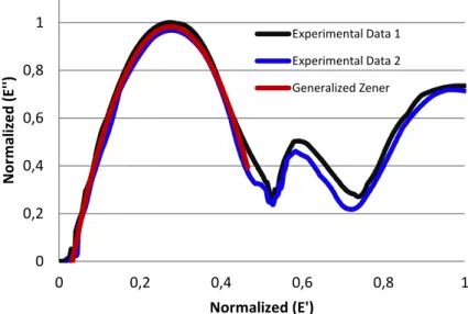
DMTA analyses in both tensile and shear loadings reveal that the PA66 is viscoelastic. The Cole-Cole diagram of its tensile modulus (Fig. 1) shows three phase transitions. The first peak, corresponding to the glass transition, is the lone one of practical interest, due to its range of time and temperature. Inverse methods are applied to find the most adapted viscoelastic model for PA66. A comparative study is done between different models: Zener and its generalized version, Maxwell and its, and other methods accounting for peak asymmetry as the one of Havriliak and Negami [20]. Generalized Zener ends up to be the best model to fit the experimental data and to capture the matrix viscoelasticity. A simple Zener model would thus be enough if one neglects the dissipation aspect or if the related parameters depends on the environmental conditions (temperature and RH).
Figure 1: Normalized Cole-Cole diagram of the PA66 tensile modulus. Two dataset from DMTA are fitted with the same generalized Zener model.
3 DAMAGE MECHANISMS
Previous work on damage mechanisms [1-6] lead to the consideration of three damage mechanisms within our modeling philosophy: fiber breakage, matrix microcracking and interfacial debonding (fiber/matrix). These processes all occur at microscale but there is still a scale difference between them. Matrix micro-cracking and fiber breakage occur at fiber level, while coating degradation (interfacial debonding) takes place at a relatively smaller scale. This justifies applying continuum damage theory to the mechanism associated with the coating [21-22]. The three damage mechanisms are separately implemented.
3.1 Fiber breakage
When a fiber breaks, the related volume fraction (as well as the one of its coating) decreases in favor of the broken fiber phase with the same orientation (and respectively its coating). Fiber breakage was modeled with a Weibull-like law which computes the damage rate at each time step. This phenomenological approach is based on the work of Meraghni and Desrumaux [23]. This damage mechanisms is experimentally proven to occur for low moisture content and at start of fatigue life. The hypothesis is here that a few specific fiber setup will induce local stresses high enough to break some fibers. Such specific configuration are then supposed to be rarer as the loading goes on. The modified Weibull law accounts for this effect (2).
0 0,2 0,4 0,6 0,8 1 0 0,2 0,4 0,6 0,8 1 N o rm al ize d (E '') Normalized (E') Experimental Data 1 Experimental Data 2 Generalized Zener
(2)
(m) is a shape coefficient, 0 a stress threshold, a time constant, et the parameters linked to damage saturation. eq is the inclusion Von Mises stress.
3.2 Matrix micro-cracking
Matrix micro-cracks mainly come from two sources. On one hand, the stress concentration of local fiber setup will induce crack initiation and propagation, especially if there is already a fiber breakage. On the other hand, the damage accumulation inside the composite leads the loading to be more and more transferred to the matrix, until material rupture. The first effect is modeled in a similar way than fiber breakage. The second one is expressed as a damage dependant exponential phenomenon (3). When the matrix damage parameter rises, the matrix volume fraction decreases in favor of void one. The void aspect ratio is set to 1 (spherical), but further analyses would lead the void shape to be orthogonal to the main loading direction.
(3)
(m) is a shape coefficient, 0 a stress threshold, a time constant, et the parameters linked to damage saturation. eq is the matrix Von Mises stress. () and () are the parameters linked to void coalescence and its exponential propagation near the end of fatigue life.
3.3 Damage at interface
Interfacial debonding, mainly initiating at fiber ends, plays a crucial role in material life. This damage mechanism occurs at relatively small stresses and continually modifies the composite behavior. The chosen approach is based on Jendli's et al. work [24]. The developed damage law derived from a quadratic rupture criterion of the interface (4). The latter depends on shear and normal N interface stresses, which can be obtained by partially computing the stress jump at interface, as done by Meraghni et al. [25]. These two stress components can then be computed at each ellipsoid point. rupture and rupture are respectively the maximum normal et tangential stresses prior to debonding.
(4)
To be accounted for the micromechanical approach, this criterion has to be expressed in a probabilistic way. This allows the damage at interface to be computed with any stress tensor. This is ensured by a normal distribution N (5) which adds two parameters : a shape one µ and a damage threshold (between 0 and 100%). The latter adjusts the mean and the standard deviation sd of the normal distribution in order to get 99% damage within the rupture criterion (6). sd0 is the standard deviation when there is 99% damage on the rupture criterion for equal to 0. The incremental model
requires a consistent damage rate to be computed, and a normalization is thus done with a time constant and the damage d from the previous time step.
(5)
A last normalization has to be made due to the normal density function having strictly positive value on ]-∞; +∞[. The interesting values of the rupture criterion are between 0 and 1. Interval [1; +∞[ is inherently taken into account, in contrary to ]-∞; 0] which is then removed (7).
(7)
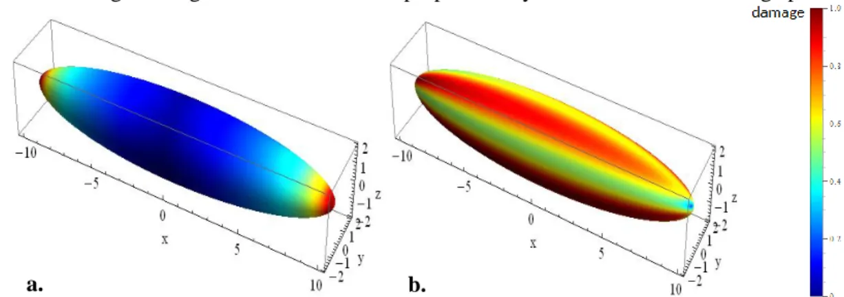
In literature, the damage at interface is often only computed along one fiber equator [25]. Figure 2 here shows that this limits the ability to find the maximum damage value. The ellipsoid has thus to be meshed and the damage parameter computed on each point of this mesh. This is also valid in pure tensile setup: the shear stress at fiber extremities can shift the point of maximum damage.
In a continuum damage mechanics framework, this law will reduce the mechanical properties of the related coating. Its tangent modulus will then proportionally decreases with the damage parameter.
Figure 2: Ellipsoidal fiber under a. traction b. a random loading. µ = ½ and = 0
3.4 Influence on transfer load
Reducing the mechanical properties of the coating is not enough to capture the influence of damage at interface on load transfer. A specific low has thus to implemented and is here inspired from the Shear Lag Model (SLM). A brief reminder of the method is here done. Further details about the equations and hypothesises of the SLM can be found in Nairn's paper [26].
The fiber is here assumed cylindrical. The SLM ends up with a differential equation (8) involving the stress in a fiber section according to its abscissa z (axis origin is set at centre of the fiber of length
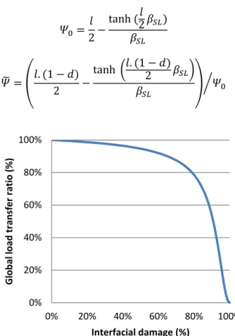
l). SL is the shear lag parameter as defined by McCartney [27] and Nayfeh [28]. It only depends on material properties, which constitutes one of the strength of this approach. f ∞ is the theoretical stress in a fiber section if the fiber is infinitely long. The differential equation is then integrated, assuming no stress at fiber extremities (9). This is equivalent to debonding at fiber ends and represents the most common case of damage initiation at interface [1-5]. This equation in fact defines the effective load transfer in each fiber section. A new integration on half the fiber is then done to get the average load transfer Ψbetween the fiber and the coating (10). Damage can now be added to the law through the following hypothesis: it decreases the effective fiber length involved in the real transfer load . This length is indeed reduced by the damage percentage (11). A normalization is finally required to ensure a load transfer equal to 100% at virgin state. This law is shown in figure 3. At the loading beginning, the load transfer does not decrease a lot with damage. When a critical value is reached, it decreases faster until interface rupture.
∞ (8) ∞ (9) b. a.
(10) (11)
Figure 3: Load transfer between fiber and coating according to damage at interface
3.5 Effective behavior
The implementation of the previous mechanisms follows the literature philosophy [1-5]. What's more is that they are each implemented with an independent law, and are thus competing with each other. Damage scenario is then only driven by the evolution law parameters, despite being designed from experimental observations.
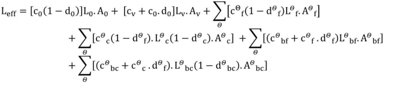
At virgin state of the composite, most of the loading is transferred to fibers. Stress at interface raises, leading to a gradual degradation of the coating; especially for the orientation families parallel to the loading direction. The coating tangent modulus proportionally decreases with damage at interface. The effective behavior is not impacted as long as the load transfer between fiber and coating is not reduced too much by the relative law (11). When the latter is compromised, the matrix is under heavier loading and thus starts to crack. Its volume fraction decreases in favor of the void one. In the meantime, local and specific fiber setups are leading to stress concentration which eventually leads to some fibre breakages and matrix micro-cracks. The fiber volume fraction (and the one of the related coating) thus decreases in favor of the one of broken fiber phase (and the one of their coating), with respect to orientation families. The matrix is finally damaged enough to make the voids coalesce and propagate in a brittle way. The mesoscale crack rapidly grows and leads to material ruin. The non-linear visco-damage behavior of the composite does not allow for a direct access to a macroscopic damage parameter. The effective modulus of the RVE can however be written based on equation 1 (12). All the properties but damage parameters are the initial ones. Strain localization tensors A are obtained with the Mori-Tanaka equations adapted to coated reinforcements. Indices 0, v, f, c, bf, et bc respectively stand for matrix, voids, fibers, coatings, broken fibers and their coatings. Θ is an orientation family and L a tangent modulus (Lv is thus a null tensor but is still written for sake of understanding). 0% 20% 40% 60% 80% 100% 0% 20% 40% 60% 80% 100% Gl ob al load t ransf er r ati o (% ) Interfacial damage (%)
(12)
4 IDENTIFICATION STRATEGY
The developed micromechanical model involves a lot of material parameters, ranging from composite and phase properties to damage law coefficients. A specific identification strategy is thus required to uncouple these parameters as far as possible. Their interdependency indeed prevents a rigorous identification from macroscopic data only. Firstly, the microstructure properties can be determined with the µCT and the in-situ SEM test. Moreover, the matrix rheology is the lone phase with a behavior complex enough to require a dedicated identification. Last but not least, damage parameters are assumed identical in both quasi-static and fatigue [1,3]. Their identification is first approximately done with experimental observations and then more accurately with specific optimization tools. Reverse engineering algorithm here combines a genetic approach with a Levenberg-Marquardt method [29].
4.1 Microstructure identification
The most important aspect of the composite microstructure is the fiber orientation distribution within the material. One can here make the most of µCT analysis. Each element is differentiated by its aspect ratio and its 3D volume. If it is a fiber, the 3D volume is added to the fiber volume fraction of the relative orientation family, as µCT gives oriented elements. ODF can thus be computed in every composite layer or within the whole sample. Figure 4 shows experimental data obtained on half the thickness of two samples of injection molded PA66/GF30. Optimization algorithm modeled the two curves with a chosen analytical function. A Pearson VII function with two peaks here fits the two datasets. The resulting ODF can be send as input in the micromechanical model, dividing the fiber/coating phases into different orientations with appropriate volume fractions.
Figure 4: ODF identification for two PA66/GF30 datasets obtained by µCT.
Furthermore, coating characteristics are determined thanks to in-situ SEM tests. The damage area around fibers is estimated during several loading phases and an average coating semi-axe is found. The fiber and its coating are not homothetic but their border are assumed equidistant. The coating semi-axes are then the fiber one plus a constant, given by the previous experimental observations. The coating aspect ratio can then be defined. Its volume fraction is consequently set by the one of fibers and by their own aspect ratio.
0 0,1 0,2 0,3 0,4 0,5 0 30 60 90 120 150 180 Or ie n tat io n d e n si ty fu n ction Angle (°) Exp. A Exp. B
4.2 Matrix properties
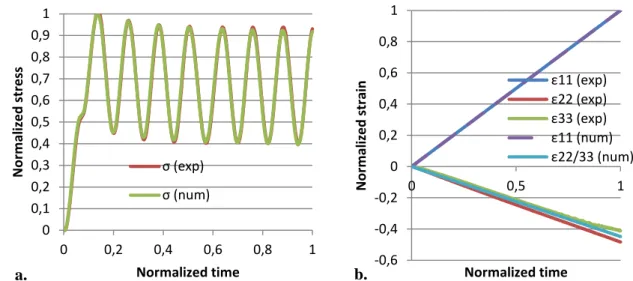
Dissipative aspect is here neglected. According to section 2.2, the polyamide-66 can then be approximated by a Zener model, here in 3D, whose equations are inspired from the ones of Richter [30]. The identification of this isotropic rheological model is done with stress/strain curves from both quasi-static and cyclic tests. The optimization algorithm gives consistent results whatever the applied frequency or the hydrothermal conditions. Figure 5 shows the result identified on both a quasi-static and a cyclic test at 1 Hz frequency with a loading ratio equal to 0.5. The obtained curves perfectly fit the data but the identified parameters depend on test conditions.
Figure 5: 3D Zener parameter identification based on both a. an strain controlled oligo-cyclic test and b. a quasi-static test to get the other component of the isotropic stiffness tensor
4.3 Damage mechanisms identification strategy
Identification of the different damage mechanisms is on-going and will be presented during the conference. Fiber breakage parameters can be estimated with µCT analyses. The number of broken fibers is the number of new fiber elements as recognized by Aviso, as the loading goes along. An appropriate thresholding has to be applied to distinguish matrix, fibers and voids; while knowing the stress state at observation areas. As far as matrix micro-cracking is concerned, it should not be a governing process until late fatigue life, where there is damage accumulation and interface saturation. Coating degradation can thus be identified with macroscopic data while considering the first part of material life. The second one will allow to calibrate the RVE meso-crack evolution. The parameters of those two damage mechanisms can finally be refined together.
5 CONCLUSIONS
A incremental micromechanical model with Mori-Tanaka homogenization has been developed to compute the fatigue behavior of polyamide-66 reinforced by 30%wt short glass fibers. The model accounts for the composite microstructure, the matrix viscoelasticity and the damage evolution. The damage mechanisms, previously identified by many authors [1-5], have been implemented through evolution laws depending on microscale variable such as local stress. A specific law, inspired by the shear lag model, has been derived to take into account the load transfer evolution according to the damage at interface. The identification strategy takes advantage of the multiscale experimental data, using reverse engineering methods and allowing to uncouple the different phenomena. Its validation is on-going and will be presented during the conference.
0 0,1 0,2 0,3 0,4 0,5 0,6 0,7 0,8 0,9 1 0 0,2 0,4 0,6 0,8 1 N o rm al ize d str e ss Normalized time σ (exp) σ (num) -0,6 -0,4 -0,2 0 0,2 0,4 0,6 0,8 1 0 0,5 1 N o rm al ize d str ai n Normalized time ε11 (exp) ε22 (exp) ε33 (exp) ε11 (num) ε22/33 (num) a. b.
REFERENCES
[1] N. Sato, T. Kurauchi, S. Sato and O. Kamigaito, Microfailure behaviour of randomly dispersed short fibre reinforced thermoplastic composites obtained by direct SEM observation, Journal of
Materials Science, 1, 1991, pp. 3891-3898.
[2] J.J. Horst and J.L. Spoormaker, Fatigue fracture mechanisms and fractography of short glass fibre reinforced polyamide 6, J. Mater. Sci., 32, 1997, pp. 3641-3651.
[3] M. F. Arif, N. Saintier, F. Meraghni, J. Fitoussi, Y. Chemisky and G. Robert, Multiscale fatigue damage characterization in short glass fiber reinforced polyamide-66, Composites Part B:
Engineering, 61, 2014, pp. 55-65.
[4] M. F. Arif, F. Meraghni, Y. Chemisky, N. Despringre and G. Robert, In situ damage mechanisms investigation of PA66/GF30 composite: Effect of relative humidity, Composites
Part B: Engineering, 58, 2014, pp. 487-495.
[5] F. Cosmi and A. Bernasconi, Micro-CT investigation on fatigue damage evolution in short fibre reinforced polymers, Composites Science and Technology, 79, 2013, pp. 70-76.
[6] J. Fitoussi, M. Bocquet and F. Meraghni, Effect of the matrix behavior on the damage of ethylene–propylene glass fiber reinforced composite subjected to high strain rate tension,
Composites Part B: Engineering, 45, 2013, pp. 1181-1191.
[7] A. Launay, M. H. Maitournam, Y. Marco and I. Raoult, Multiaxial fatigue models for short glass fiber reinforced polyamide – Part I: Nonlinear anisotropic constitutive behavior for cyclic response, International Journal of Fatigue, 47, 2013, pp. 382-389.
[8] A. Launay, M. H. Maitournam, Y. Marco and I. Raoult, Multiaxial fatigue models for short glass fibre reinforced polyamide. Part II: Fatigue life estimation, International Journal of
Fatigue, 47, 2013, pp. 390-406.
[9] H. Nouri, F. Meraghni and P. Lory, Fatigue damage model for injection-molded short glass fibre reinforced thermoplastics, International Journal of Fatigue, 31, 2009, pp. 934-942. [10] I. Doghri, L. Adam and N. Bilger, Mean-field homogenization of elasto-viscoplastic composites
based on a general incrementally affine linearization method, International Journal of
Plasticity, 26, 2010, pp. 219-238.
[11] S. Kammoun, I. Doghri, L. Adam, G. Robert and L. Delannay, First pseudo-grain failure model for inelastic composites with misaligned short fibers, Composites Part A: Applied Science and
Manufacturing, 42, 2011, pp. 1892-1902.
[12] T. Mori and K. Tanaka, Average stress in matrix and average elastic energy of materials with misfitting inclusions, Acta Metall., 21, 1973, pp. 571-574.
[13] H.L. Cox, The elasticity and strength of paper on other fibrous materials, Br. J. Appl. Phys., 3, 1952, p. 72.
[14] F. Desrumaux, F. Meraghni and M. L. Benzeggagh, Generalized Mori-Tanaka Scheme to Model Anisotropic Damage Using Numerical Eshelby Tensor, Journal of Composite Materials, 35, 2001, pp. 603-624.
[15] Z. Jendli, F. Meraghni, J. Fitoussi and D. Baptiste, Multi-scales modelling of dynamic behaviour for discontinuous fibre SMC composites, Composites Science and Technology, 69, 2009, pp. 97-103.
[16] D. C. Lagoudas, A. C. Gavazzi and H. Nigam, Elastoplastic behavior of metal matrix composites based on incremental plasticity and the Mori-Tanaka averaging scheme,
Computational Mechanics, 8, 1991, p. 193.
[17] A. C. Gavazzi and D. C. Lagoudas, On the numerical evaluation of Eshelby's tensor and its application to elastoplastic fibrous composites, Computational Mechanics, 7, 1990, p. 13. [18] M. Cherkaoui, H. Sabar and M. Berveiller, Elastic composites with coated reinforcements: A
micromechanical approach for nonhomothetic topology, International Journal of Engineering
Science, 33, 1995, pp. 829-843.
[19] E. Hervé and A. Zaoui, n-Layered inclusion-based micromechanical modelling, International
Journal of Engineering Science, 31, 1993, pp. 1-10.
[20] S. Havriliak and S. Negami, A complex plane representation of dielectric and mechanical relaxation processes in some polymers, Polymer, 8, 1967, pp. 161-210.
[21] J. L. Chaboche, Continuous damage mechanics: A tool to describe phenomena before crack initiation, Nuclear Engineering and Design, 64, 1981, pp. 233-247.
[22] D. Krajcinovic, Continuum damage mechanics, Applied Mechanics Reviews, 37, 1984, pp. 1-6. [23] F. Meraghni, F. Desrumaux and M. L. Benzeggagh, Implementation of a constitutive
micromechanical model for damage analysis in glass mat reinforced composite structures,
Composites Science and Technology, 62, 2002, pp. 2087-2097.
[24] Z. Jendli, F. Meraghni, J. Fitoussi and D. Baptiste, Multi-scales modelling of dynamic behaviour for discontinuous fibre SMC composites, Composites Science and Technology, 69, 2009, pp. 97-103.
[25] F. Meraghni, C. J. Blakeman and M. L. Benzeggagh, Effect of interfacial decohesion on stiffness reduction in a random discontinuous-fibre composite containing matrix microcracks,
Composites Science and Technology, 56, 1996, pp. 541-555.
[26] J.A. Nairn, On the use of shear-lag methods for analysis of stress transfer in unidirectional composites, Mechanics of Materials, 26, 1997, pp. 63-80.
[27] L.N. McCartney, Stress Transfer for Multiple Perfectly Bonded Concentric Cylinder Models of
Unidirectional Composites, National Physical Laboratory Report DMM(A)129, Teddington,
UK, 1993.
[28] A.H. Nayfeh, Thermodynamically induced interfacial stresses in fibrous composites, Fibre Sci.
& Tech., 10, 1977, p. 195.
[29] F. Meraghni, Y. Chemisky, B. Piotrowski, R. Echchorfi, N. Bourgeois and E. Patoor, Parameter identification of a thermodynamic model for superelastic shape memory alloys using analytical calculation of the sensitivity matrix, European Journal of Mechanics - A/Solids, 45, 2014, pp. 226-237.
[30] F. Richter, Upsetting and Viscoelasticity of Vitreous SiO2: Experiments, Interpretation and