© Ruichao Xie, 2021
A Novel Wide-Area Control Strategy for Damping of
Critical Frequency Oscillations via Modulation of Active
Power Injections
Thèse
Ruichao Xie
Doctorat en génie électrique
Philosophiæ doctor (Ph. D.)
ii
R
ÉSUMÉCette thèse propose une nouvelle stratégie d'amortissement des oscillations de fréquence critiques par la modulation de l'injection rapide de puissances actives, qui ouvre la voie à l'utilisation d'actionneurs géographiquement dispersés, par exemple des ressources énergétiques distribuées (DERs), dans le contrôle des basses fréquences dynamique de l'angle du rotor du réseau électrique, qui comprend les oscillations interzones et les oscillations de fréquence transitoire. La méthode proposée intègre ces deux dynamiques différentes dans un cadre basé sur un système linéaire invariant dans le temps, dans lequel le contrôle de l'oscillation de fréquence transitoire est traduit en contrôle de la dynamique de mode commun du système. A cet effet, un examen attentif de la relation entre la variation transitoire de fréquence et la dynamique du mode commun est effectué; Les simulations montrent que le mode commun définit la forme d'un changement transitoire de faible signal de fréquence. La méthode de contrôle proposée vise à utiliser efficacement la réserve de marche limitée des DERs existants pour atténuer ces oscillations. Ceci est réalisé en découplant les actions de commande d'amortissement à différents endroits en utilisant les signaux d'oscillation du mode concerné comme commandes de puissance. Une base théorique pour cette commande de modulation découplée est fournie. Techniquement, les signaux d'oscillation modale souhaités sont filtrés en combinant linéairement les fréquences de l'ensemble du système, ce qui est déterminé par la technique (LQRSP). Avec la stratégie proposée, la modulation de chaque injection de puissance active peut être conçue efficacement en tenant compte de la limite de réponse et de la capacité de sortie en régime permanent du dispositif de support. Dans le cadre proposé, le signal de commande pour la commande de fréquence primaire est automatiquement déterminé dans une direction de commande (presque) optimale; des expériences montrent que ce signal a tendance à être la vitesse du système vue par le point d'injection de puissance. La commande modulante découplée a tendance à isoler les actions de commande pour les oscillations interzones et les oscillations de fréquence transitoire, ce qui atténue grandement les préoccupations concernant l'interaction entre la commande de ces deux types de dynamiques.
iii
A
BSTRACTThis dissertation provides a novel wide-area control strategy for damping of critical frequency oscillations via modulation of fast active power injections, which paves the way for the utilization of large-scale geographically dispersed actuators, e.g., distributed energy resources (DERs), in the control of power system low-frequency rotor angle dynamics, this includes the inter-area oscillations and the transient frequency swing. The proposed method incorporates these two different dynamics into a linear time invariant (LTI) system based control framework, in which the control of the transient frequency swing is translated into the control of the system common mode dynamics. For this purpose, a careful examination of the relationship between the transient frequency swing and the common mode dynamics is carried out; extensive simulations show that the common mode defines the shape of a small-signal transient frequency swing. The proposed control method pursues an efficient utilization of the limited power reserve of existing DERs to mitigate these oscillations. This is accomplished by decoupling the damping control actions at different sites using the oscillation signals of the concerned mode as the power commands. A theoretical basis for this decoupled modulating control is provided. Technically, the desired sole modal oscillation signals are filtered out by linearly combining the system-wide frequencies, which is determined by the linear quadratic regulator based sparsity-promoting (LQRSP) technique. With the proposed strategy, the modulation of each active power injection can be effectively engineered considering the response limit and steady-state output capability of the supporting device. In the proposed control framework, the power command signal for the primary frequency control is determined in a (near) optimal control sense; experiments show that this signal tends to be the system speed seen by the power injection point. Importantly, the decoupled modulating control tends to isolate the control actions for the inter-area oscillations and the transient frequency swing, thereby greatly relieving the concern about the interaction between the control of these two types of dynamics.
iv
T
ABLE OFC
ONTENTSRésumé ... ii
Abstract ... iii
List of Figures ... v
List of Tables ... vii
List of Publications ... viii
Dedication ... ix
Acknowledgments ... x
Foreword ... xi
Introduction ... 1
Chapter 1 Small-Signal Characteristics of the Transient Frequency Swing ... 10
1.1 Résumé ... 10
1.2 Abstract... 10
1.3 Introduction... 10
1.4 A Description of the Frequency Oscillations... 13
1.5 Frequency Oscillations in a Test System ... 17
1.5.1 Impact of Hydro-Turbine Speed-Governing ... 18
1.5.2 Impact of Steam-Turbine Speed-Governing ... 21
1.5.3 Impact of Load Voltage Sensitivity ... 23
1.5.4 Impact of System Inertia... 31
1.6 Summary ... 33
Chapter 2 A Novel Wide-Area Control Strategy for Damping of Critical Frequency Oscillations via Modulation of Active Power Injections ... 35
2.1 Résumé ... 35
2.2 Abstract... 35
2.3 Introduction... 35
2.4 Static Modal Decomposition Control ... 37
2.5 A Static Multi-Point Control Strategy ... 39
2.6 Application to Multi-Point Active Power Modulation ... 41
2.7 Determination of the Input Signals Using LQRSP ... 43
2.8 Damping Controller Design Flowchart ... 46
2.9 System Description ... 47
2.10 Empirical Strategies ... 48
2.11 Proposed Solution ... 49
2.12 Comparison with an Existing Optimal Control Strategy ... 55
2.13 Simulation on a Large System ... 56
2.14 Summary ... 60
Conclusion ... 61
Appendix ... 63
v
L
IST OFF
IGURESFigure I.1: 1996 western power system breakup: California-Oregon intertie. ... 1
Figure I.2: Deployment of phasor measurement units in the North American power grid (credit: NASPI [70])... 4
Figure 1.1: Large event in Hydro-Quebec system: loss of 3842 MW of generation. At 58.14-Hz frequency dip (5s later), 2700 MW load and 2148 Mvar capacitor were shed by the wide-area RAS ... 11
Figure 1.2: Unstable 0.05Hz-common mode oscillations in a Latin America interconnection with predominately hydro-generation. ... 12
Figure 1.3: The modified four-machine test system. ... 16
Figure 1.4: System speed for Case I: no turbine governor ... 18
Figure 1.5: A simplified turbine-governor model. ... 18
Figure 1.6: System speed for Case II. Single hydro-TG. ... 19
Figure 1.7: Real and imaginary parts for −𝐺𝑡𝑔(𝑓). ... 20
Figure 1.8: System speed for Case III. Two hydro-TGs. ... 20
Figure 1.9: System speed for Case IV and Case V. Three and four hydro-TGs respectively. ... 21
Figure 1.10: Real and imaginary parts for −𝐺𝑡𝑔(𝑓). ... 23
Figure 1.11: System speed for the steam TG scenarios. One, two, three and four steam TGs. ... 23
Figure 1.12: System speed for the new load composition scenarios. ... 25
Figure 1.13: Real and imaginary parts for 𝐺𝑉𝐿𝜔𝐿(𝑓) in the range of 0.01-0.1 Hz. Case VI with hydro-TGs. ... 27
Figure 1.14: Real and imaginary parts for 𝐺𝑉𝐿𝜔𝐿(𝑓) in the range of 0.01-0.1 Hz. Case VI with hydro-TGs (Bigger PSS gain and smaller washout time constant cases)... 28
Figure 1.15: Estimated PSD spectra for the bus frequencies. Case VI for hydro-TGs. ... 29
Figure 1.16: Estimated relative phase for the bus frequencies. Case VI for hydro-TGs. .... 29
Figure 1.17: Real and imaginary parts for 𝐺𝑉𝐿𝜔𝐿(𝑓) in the range of 0.1-1 Hz for bus 4 and bus 14 respectively. Case VI with hydro-TGs. ... 30
Figure 1.18: Common mode movement w.r.t the change of inertia (Kundur’s system). .... 31
Figure 1.19: Common mode movement w.r.t the change of inertia. (New England 39-bus system) ... 33
Figure 1.20: System speed for the New-England test system after outage of generator 6 and 1: Same regulation capacity, different inertias. ... 33
Figure 2.1: The controller for the 𝑗𝑡ℎ mode at system input (#𝑑). ... 39
vi
Figure 2.3: Design flowchart of the damping controllers for a particular mode. ... 46
Figure 2.4: Two-area system. D1 and D2 are the integrated power devices. ... 47
Figure 2.5: Root locus, two-area system case. ... 49
Figure 2.6: Magnitude frequency response of the open-loop transfer. ... 51
Figure 2.7: Sparsity-promoting results. card = cardinality. (𝐽 − 𝐽𝑐)/𝐽𝑐 denotes the quadratic performance degradation of a sparse gain matrix 𝑭𝑠 relative to the optimal gain matrix 𝑭𝑐. ... 51
Figure 2.8: Closed-loop system modes. ... 52
Figure 2.9: Relative speed of generators 1 and 3... 52
Figure 2.10: COI speed. ... 53
Figure 2.11: Power responses of the devices. Proposed method vs [45]. ... 53
Figure 2.12: Relative speed of generators 1 and 2. ... 54
Figure 2.13: Power responses of the devices. Proposed method vs [45] with reduced gain. ... 54
Figure 2.14: New England 39-bus system. Blue circles denote the integrated active power injection devices. ... 56
Figure 2.15: Modal controllability of the devices. (a) 0.6 Hz inter-area mode. (b) The common mode. Selected devices for controlling each mode are encircled. ... 58
Figure 2.16: ‘Root locus’, New England 39-bus system case. ... 58
Figure 2.17: (a) Power export of the NE system. (b) COI speed. ... 59
vii
L
IST OFT
ABLESTable 1.1: Load Composition: Constant Power Loads ... 17
Table 1.2: System Rotor-Speed Modes for Hydro-Dominated System ... 18
Table 1.3: Parameters for A Hydro-Type TG ... 19
Table 1.4: Parameters for A Steam-Type TG ... 21
Table 1.5: System Rotor-Speed Modes for Steam-Dominated System ... 24
Table 1.6: Load Composition: Mixed Constant Power and Constant Impedance Loads .... 24
viii
L
IST OFP
UBLICATIONSR. C. Xie, I. Kamwa, D. Rimorov, and A. Moeini, "Fundamental study of common mode small-signal frequency oscillations in power systems," International Journal of Electrical Power and Energy Systems, vol. 106, pp. 201–209, Mar. 2019.
R. C. Xie, I. Kamwa, and C. Y. Chung, " A novel wide-area control strategy for damping of critical frequency oscillations via modulation of active power injections," IEEE Transactions on Power Systems, vol. 36, no. 1, pp. 485–494, Jan. 2021.
ix
D
EDICATION For my parentsx
A
CKNOWLEDGMENTSI wish to thank my supervisor, Dr. Innocent Kamwa. His guidance, helpful discussions, and constructive criticism throughout my studies have been extremely helpful. I wish to thank my supervisor Dr. Hoang Le-Huy for his guidance, suggestions, and help throughout my studies. I wish to express my sincere appreciation to Dr. C. Y. Chung at the University of Saskatchewan for research supervision. I wish to thank Dr. Jérôme Cros for his invaluable support and encouragement. I wish to express my appreciation to Dr. André Desbiens, Mrs. Nancy Duchesneau, and Mr. Raoult Teukam Dabou for their invaluable help and support.
I wish to thank the smart lab members at the University of Saskatchewan for their help and insightful discussions during my visiting study.
I would also like to thank Dr. Dmitry Rimorov for many discussions related to power system dynamics.
xi
F
OREWORDThis dissertation is comprised of the contents presented in two published journal papers [A] and [B]. The goal of this work is to develop a control method that can handle large-scale geographically dispersed actuators for controlling power system low-frequency rotor angle dynamics. The paper [B], which presents the newly derived control method, is inserted in Chapter 2. The paper [A] is inserted in chapter 1; the study presented therein provides a strong support to incorporating the control of the transient frequency swing into a linear time invariant system based control framework, which is an essential basis for the proposed control method.
[A] R. C. Xie, I. Kamwa, D. Rimorov, and A. Moeini, "Fundamental study of common mode small-signal frequency oscillations in power systems," International Journal of Electrical Power and Energy Systems, vol. 106, pp. 201–209, Mar. 2019.
My author status: first author.
My role in preparing this article: Developed the approach; conducted simulations; wrote and revised the paper.
The role of co-authors in preparing this article: Provided important guidance and insightful suggestions.
[B] R. C. Xie, I. Kamwa, and C. Y. Chung, "A novel wide-area control strategy for damping of critical frequency oscillations via modulation of active power injections," IEEE Transactions on Power Systems, vol. 36, no. 1, pp. 485–494, Jan. 2021.
My author status: first author.
My role in preparing this article: Developed the approach; conducted simulations; wrote and revised the paper.
The role of co-authors in preparing this article: Provided important guidance and insightful suggestions.
1
I
NTRODUCTIONThe Research Problem
The electric power industry is undergoing an unprecedented change in its energy structure. Driven by the primary goal of reducing the greenhouse gas emissions and increasing the system operational flexibility, many utilities are integrating electronically interfaced distributed energy resources (DERs), such as wind, solar and energy storage systems, into their transmission networks. Such an energy transition also brings new opportunities to the field of power system control. An emerging topic is the utilization of large-scale DERs in the control of the low-frequency rotor angle dynamics; this includes the inter-area oscillations and the transient frequency swing [12, 37-41]. The transient frequency swing is a process of the system converging to a new synchronous reference while the inter-area oscillations involve different groups of synchronous machines oscillate against each other around the system synchronous reference [61]. A sudden generation/load imbalance would significantly excite these two types of dynamics that threaten the reliability of the system operation. A real-life event is shown in Fig. I.1, which shows the devastating effect of such disturbances. The energy devices integrated using modern converters can usually provide the fast active power modulation capability; therefore, proper modulating actions may significantly improve the performance of the frequency dynamics due to the strong coupling of these two physical variables (i.e., active power vs. frequency) seen by the transmission system.
2
Although promising, the DER-based damping control has been facing a fundamental challenge; that is, the power modulating actions must take into account the response limit and steady-state output capability of the supporting devices. Moreover, since the power devices are integrated for the consideration of economic operation, the headroom of individual devices for dynamic response may be small. As a result, it may need to take the efforts of many such devices to achieve a desired control effect. Intuitively, geographically dispersed actuators increase the controllability for the system-wide frequency oscillations while reducing the control burden at each single control site. However, in the context of classical dynamic and static feedback control, this may also significantly increase the computational burden brought about by the coordination of numerous controllers. To the best knowledge of the author, handling this problem with traditional control design is very difficult, especially when the amount of the controlled actuators is large. From the viewpoint of dynamics, the transient frequency swing is different from the inter-area oscillations. How to simultaneously mitigate them in a scientific way is never an easy task. Although many have used the linear method to analyze and control the transient frequency swing [3, 12, 19, 32], a control method that can effectively incorporate these two types of dynamics into a single framework is missing. In the context of the so-called grid following control, there is an ongoing research on the choice of command signals for the fast active power modulation based primary frequency control. Literature shows three directions in this line of research: using the system frequency as the power command signal to provide the so-called fast frequency response [39], using the derivative of the system frequency as the power command signal to provide the so-called virtual inertia [68], and a combination of them [12, 37]. How to effectively determine and manage the power command signals is still an open question.
This dissertation focuses on this so-called multi-point active power modulation problem and is devoted to developing a wide-area control method that can handle large-scale actuators while taking into account the above-mentioned challenges. From a broad point of view, the development of such a control method may also be useful for the utilization of other types of actuators in damping control.
3
Literature Review
Wide-Area Damping Control
The basic idea of wide-area damping control is using the remote measurements to drive the actuators such as synchronous machines, HVDC, dynamic loads, and DERs so as to achieve better control effect [63-64]. Taking the synchronous machines as an example, this section provides a general review of the damping control problem and highlights the advantage of the wide-area signals based damping control.
Modern power system typically involves power exchange between balancing areas. Consequently, poorly damped inter-area oscillations may occur, thereby limiting the capability of the power transfers. Under certain operating conditions, the inter-area mode may become lightly damped or even unstable. It is therefore desirable to take effective control actions to mitigate the oscillations. The damping control in power systems may be achieved via modulation of the excitation system of the synchronous machines [23]. The power system stabilizer (PSS), a dynamic feedback controller typically using the machine speed as input, drives the generator to induce a damping torque component on the turbine shaft so as to attenuate the machine speed deviations [23]. The modulation of excitation system has proved effective for mitigating the local oscillations; however, for the inter-area oscillations that involve energy exchange between different groups of synchronous machines, the decentralized damping control is usually less effective. Moreover, the 𝜔 → 𝑉𝑟𝑒𝑓 feedback control loop is usually more sensitive to the generator’s local mode; as a result, a zero of the open-loop system transfer function may be located near the inter-area mode [51], thereby limiting the movement of the inter-area mode in the complex plane under power system stabilizer (PSS) actions. To overcome this issue, PSS4B (a multi-band PSS) [32] to limit the movement of the local mode or filter PSS (FPSS) [42] to make the PSS focus on the inter-area mode may be required. When considerable PSSs are tuned to achieve a better damping control effect on both the local and the inter-area modes of oscillations of a large power system, the coordination of multiple dynamic feedback controllers is not a trivial task [32]. After several decades of development, the phasor measurement unit (PMU) has been widely deployed in the North American power grids as depicted in Fig. I.2. This allows the local controllers access remote measurements [32]. Importantly, the wide-area signals may help
4
constitute a decentralized/hierarchical control strategy, which has proved more effective than the decentralized control [32].
Figure I.2: Deployment of phasor measurement units in the North American power grid (credit: NASPI [70]).
Traditionally, for the damping control of inter-area modes, the actuators that execute the control actions usually need to be determined in the first place, as the inter-area modes are usually controllable at certain locations. Many small-signal analysis tools may achieve this: 1). Using eigen-decomposition of the state-space model of a power system to obtain the distributions of the controllability and observability or the residues matrix [23]; 2). Obtaining the above measures via impulse response based system identification [51]. Such approaches may be effective for the evaluation of the same type of actuators; however, when different types of actuators and feedback signals need to be determined, the eigenvector index may have scaling problem. In this regard, the geometric measure has proved more general and effective [32]. This measure is especially useful for selecting remote feedback signals to increase the controller’s controllability. For example, the tie-line powers or currents may carry more rotor dynamics information than the bus frequency in some cases [52]. Although
5
the conventional modal indexes offer insight into the wide-area damping control design in terms of selecting the actuators and the feedback signals, they may not be able to guarantee the selected actuators to be sufficient in constituting an efficient control structure, in which a variety of local and remote system outputs may be employed [32]. Once the actuators and the feedback signals are determined, damping controllers can be designed. For a single actuator based damping control, the classic root-locus technique may be used to tune the controller parameters (gain and/or compensator time constants) [51]. If multiple controllers are involved, optimization process may be needed to coordinate the controllers in order to achieve a desired closed-loop system performance and the sequential control design may be employed [32]. In general, the control design is a computer-assisted work, and the basic process is setting a desired performance index as well as several constraints and solving for possible combinations of the controller parameters using optimization techniques. The performance index and constraints may be the 𝐻2 and/or 𝐻∞ index, eigenvalue index, saturation limits, and robustness considerations [32, 53-55].
Recently, taking advantage of the newly developed ADMM technique [71], a linear quadratic regulator based sparsity promoting (LQRSP) optimal control framework is established [44]. A salient feature of the approach is that it can identify a sparse control structure while optimizing the closed-loop system performance [45-46]. However, as will be explained in chapter 2 and Appendix, the control design method may not be applicable for the DER-based control.
Active Power Modulation Based Damping Control
Power system community has a long history of studying and practicing the active power modulation based damping control. An early attempt is the PDCI damping controller [48]. Because the DC line connects two oscillating areas, the modulating control showed significant effect on a major inter-area mode of the system. However, due to the restrictions on the choice of feedback signals, the controller was implemented with filtered local available measurements passing through a fine tuned compensator. Unluckily, unwanted control interactions appeared under certain operating conditions. With the advance of wide-area measurement system, recently it has been demonstrated that modulating the active power injection of a HVDC using the frequency difference of the DC line terminals (AC side) as
6
command signal to damp the critical inter-area oscillation of a large-scale power system is technically feasible [35-36]. However, the number of HVDC in a power system is usually limited; therefore, its ability to control multiple (concerned) inter-area modes is limited. Researchers have also been exploring the control of dynamic loads. The problem of stabilizing a bulk power system by modulating controllable active loads is investigated in [48-49]. However, the dynamic feedback control design may have scaling problem. An attempt to control of massive dynamic loads is presented in [69]; simulation results show that the distributed loads have great potential to enhance the dynamic performance of the system. The emergence of DERs brings new opportunities for the active power modulation based damping control. Unlike HVDC and dynamic loads, the DERs are independent power injection devices and may provide more flexible control functions without affecting the operation of the devices. A non-linear control strategy that coordinates the DERs for damping control is presented in [56]. The approach takes into account the input constraints; however, it may suffer from scaling problem when a large amount of DERs is controlled. An adaptive wide-area damping control for DER integrated power grid is proposed in [57]. Although this type of approaches may require less system model information, the robustness of the controller with respect to disturbances may not be guaranteed, as the location of the DERs are determined by many factors. Multiple models (or model bank) based adaptive damping control [64-66] which may be applied to DERs have been proposed as well, but their robustness during short-circuit faults close to the actuator locations is yet to be demonstrated. A so-called retrofit control method is presented in [58-59]. This method controls the DERs to mitigate the local disturbances; therefore, it may not be able to provide control effect if the disturbance location nearby has no DERs. The feasibility of applying model predictive control (MPC) as a viable strategy to damp the electromechanical oscillations is investigated in [60]. Although the MPC strategy is able to take into account the input constraints, the computational burden of the MPC approach may limit its applicability for dynamic control.
Given the nature of the DER-based control, major efforts toward the multi-point active power modulation based control for damping of the inter-area oscillations and the transient frequency swing are focused on coordinating the control actions using output feedback control strategies. By using the local frequency as the power command, a design method of
7
structurally constrained output feedback with bounded power responses is proposed in [37]; a non-linear simulation based optimization approach for coordinating the power modulations to damp the critical mode of oscillation is proposed in [38]; likewise, a gain tuning approach of load modulation for primary frequency regulation while considering the load’s disutility is presented in [39]. The other method employs the system-wide frequencies to drive the active power modulations, a structurally constrained output feedback optimal control method is proposed in [40] for suppressing the inter-area oscillation of a two-area system; the approach is then further developed in [41] for controlling multiple inter-area modes while optionally improving the primary frequency response of a large-scale power system. All of these methods have distinct merits. Nevertheless, we note that the control performance of the local frequency based power modulation may be dependent on the system structure and the actuator location. We also note that although all the methods pursue an optimal coordination, the strategies may not be very cost-effective in terms of utilizing the valued active power response to resolve the oscillation issue, which is usually dictated by a couple of modes under an operating condition; moreover, the approaches are based on a centralized implementation (i.e., the modulations act as a single control action), which may yield a compromised control effect, and it is not easy to illustrate the role of each single-point control action in the oscillation damping.
Summary
The above literature survey demonstrates that achieving a high penetration of DERs to switching the economy to 100% renewable, gives rise to some major challenges in term of effectively controlling the frequency response of a system with lower inertia while ensuring adequate damping of inter-area oscillations in presence of millions of controllable agents. On one hand, we see an opportunity to use these massive DERs as so many control modulation sources that can be used to enhance the system stability without the need for additional investments. However, on the other hand, we face the challenge of an increased control complexity due to a large number of distributed actuators. Therefore, we consider that to maximize the grid hosting capability of DERs with respect to maintaining grid frequency response and dynamic stability, there are two main gaps that remain to be properly filled:
8
1). Since the inverter-based DERs are inertia-less generation, their large-scale adoption for decarbonizing the economy results inevitably in a deterioration of the frequency response of the power grid. Can we then use improved control techniques to enhance the frequency responses resulting from generation/load imbalances without deteriorating the performance of the electromechanical dynamics [67]? By strengthening the frequency response, such advanced controls based on the power modulation capability of existing assets may significantly increase the grid hosting capability of inertia-less DER.
2). Once the inverter-based DERs are massively integrated in the system without impeding the system frequency stability, thanks to the findings of the previous step, how can we leverage their active power modulation capability to enhance the overall stability of the power system with respect to the electromechanical oscillation more specifically? This is a huge challenge never addressed before, yet if successful, the DERs can become important flexible resources like smart loads, with the advantage of greater controllability thanks to their smart power electronics interface and larger total headroom available for safe and continuous action without influencing energy requirements on the grid users.
The aim of the research considered in this dissertation is to address the two research gaps identified above. We will first develop a mathematical and simulation based fundamental understanding of the common frequency oscillations in a power grid leading to identification of the underlying influencing factors. Building on this knowledge, we will develop a novel control method that has the ability to handle a large number of actuators, and effective in dealing with the two control objectives stated above.
9
The Research Work
This dissertation proposes a methodology that incorporates the transient frequency swing into a linear time invariant (LTI) system based control framework, which is usually employed for the design of electromechanical controls. In particular, the control of the transient frequency swing is translated into the control of the system common mode dynamics. To ascertain the feasibility of this substitution, the relationship between the common mode dynamics and the transient frequency swing is examined; this is presented in chapter 1 through an impact study of system components on the system frequency oscillations; simulation results clearly show that the common mode defines the shape of the transient frequency swing under relatively small disturbances. The proposed control method is presented in chapter 2. The method pursues an efficient utilization of the limited power reserve of existing DERs to mitigate the inter-area oscillations and the transient frequency swing. This is accomplished by decoupling the damping control actions at different sites using the oscillation signals of the concerned mode as the power commands. A theoretical basis for this decoupled modulating control is provided. Technically, the desired sole modal oscillation signals are filtered out by linearly combining the system-wide frequencies, which is determined by the linear quadratic regulator based sparsity-promoting (LQRSP) technique. With the proposed strategy, the modulation of each active power injection can be effectively engineered considering the response limit and steady-state output capability of the supporting device. In the proposed control framework, the power command signal for the primary frequency control is determined in a (near) optimal control sense; experiments show that this signal tends to be the system speed seen by the power injection point. Importantly, the decoupled modulating control tends to isolate the control actions for the inter-area oscillations and the transient frequency swing, thereby greatly relieving the concern about the interaction between the control of these two types of dynamics.
10
C
HAPTER1
S
MALL-S
IGNALC
HARACTERISTICS OF THET
RANSIENTF
REQUENCYS
WINGInserted paper: R. C. Xie, I. Kamwa, D. Rimorov, and A. Moeini, "Fundamental study of common mode small-signal frequency oscillations in power systems," International Journal of Electrical Power and Energy
Systems, vol. 106, pp. 201–209, Mar. 2019.
1.1 R
ÉSUMÉCe chapitre présente une étude sur les caractéristiques des petits signaux de l'oscillation de fréquence transitoire. Les résultats montrent clairement que le mode commun définit la forme d'une fréquence transitoire sous des perturbations relativement faibles.
1.2 A
BSTRACTThis chapter presents a study on the small-signal characteristics of the transient frequency swing. The results clearly show that the common mode defines the shape of a transient frequency under relatively small disturbances.
1.3 I
NTRODUCTIONIn recent years, frequency oscillations associated with primary frequency response (PFR) occurred in several isolated power systems [1-3]. In fact, such oscillatory phenomena has been noticed long time ago, especially in hydro-dominated power systems, and their detrimental impact on the interconnection reliability were recognized very early [4]. The speed-governing system settings were shown to be the culprit of the oscillations [4-8], although their deadbeat performance tuning often masks the oscillatory phenomena in interconnected systems. Furthermore, several authors found that the frequency dynamics is governed by a so-called governor mode (termed common low-frequency mode in [8] and frequency-regulation mode in [9]). Further studies in [10] show that the change of system inertia and load voltage dependence can greatly alter the common mode stability. Moreover, the common mode is controllable via excitation voltage modulation by the so-called
Multi-11
Band PSS [8,10] or through blade pitching of type-3 wind turbine generator operating in a deloaded manner [9].
A damping torque analysis is performed in [3], which points out that the hydraulic turbine-governor transfer loop is easily creating negative damping torque at the common mode frequency and parameter optimization of the PID type governor is proposed to guarantee positive damping contribution from the turbine-governor in the very-low frequency range (say 0.01-0.1 Hz).
On the other hand, power system community has studied frequency response improvement intensively, especially since the emergence of large-scale renewables and NERC studies showing a 50% performance decline from 1994 to 2018. The synchronous condenser based reactive power modulation method is proposed in [11]. An approach for optimizing the participation of distributed energy resource in primary frequency response is proposed in [12]. A practical frequency control design for large scale of power system based on Multi-Band PSS is demonstrated in [13]. In essence, such approaches intend to improve the common mode damping in order to achieve improved frequency nadir.
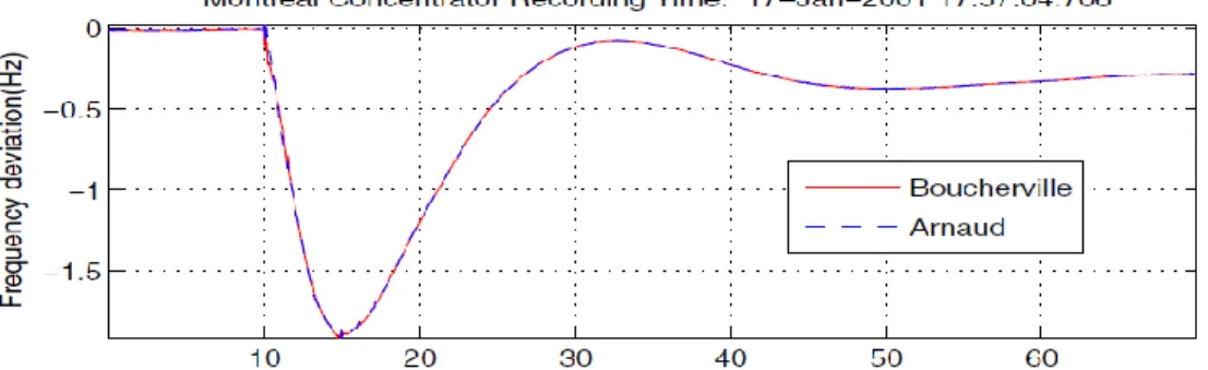
Figure 1.1: Large event in Hydro-Quebec system: loss of 3842 MW of generation. At 58.14-Hz frequency dip (5s later), 2700 MW load and 2148 Mvar capacitor were shed by
the wide-area RAS
Despite above investigations using small-signal analysis tools to approach frequency response from an oscillation damping perspective, frequency stability is still defined in terms of “the ability of a power system to maintain steady frequency following a severe system upset resulting in a significant imbalance between generation and load” [14]. Therefore, the perception reinforced by the MW/0.1Hz NERC metric is that frequency stability is a large disturbance phenomenon. While a sufficient condition, it is not a necessary one [8,15].
12
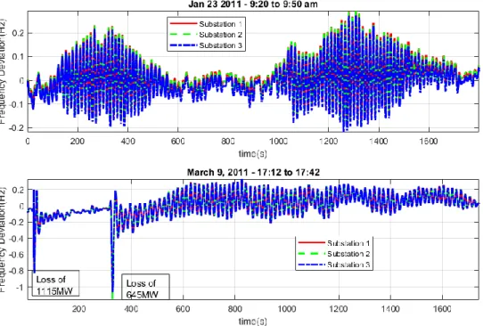
Fig. 1.1 illustrates actual frequency response in Hydro-Quebec, following a large generation-load imbalance that results in frequency swings with a nadir performance of 3842MW/1.8Hz = 213MW/0.1Hz which is better than that specified by NERC [16]. The oscillation mode shape is the same at two substations separated by 1000km (Boucherville close to Montreal and Arnaud in the North-East). Fig. 1.2 illustrates the other facet of the frequency response, highlighting the devastating impact of poor damping. On the top of Fig. 1.2, spontaneous and sustained oscillations are observed, while on the bottom of the figure, an example of poorly damped very-low frequency oscillations triggered by 10% generation lost in the hydro-dominated system is given, the system generation is 7350MW in the first stage and 6700MW in the second stage, and clearly, as inertia decreases, the common mode becomes more unstable. These actual events show that while frequency instability is generally driven by large disturbances, poorly damped common mode due to inadequate acceleration power based PSS [8] or hydro-governor settings [3] is an aggravating factor and in some cases, an enabler of small-signal spontaneous unstable oscillations.
Figure 1.2: Unstable 0.05Hz-common mode oscillations in a Latin America interconnection with predominately hydro-generation.
As illustrated by these real-world examples, although the frequency dynamics has been recognized to be driven largely by the common mode, the fundamental nature of this mode
13
is still little explored, e.g., what factor influences most the frequency and damping of this mode in an interconnected system? The primary frequency control studies usually employ a single-machine equivalent model [17] by aggregating the turbine-governors, and use a load-damping term to represent the contribution of the frequency dependent load [12, 18-19]. However, as demonstrated in [10], the voltage dependent load may greatly affect the common mode dynamics, and its contribution is not necessarily just the damping.
Building upon existing studies, this chapter picks up the damping and synchronizing torque concept to investigate on a small parametric test system, the impact of turbine-governor type, load voltage sensitivity as well as system inertia on the common mode frequency oscillations. The findings are then confirmed on the New-England 39-bus test system. The main contributions are the following: (1) Using the damping-synchronizing torque concept to exhibit analytically for the first time in the literature the impact of several factors influencing the damping and natural frequency of the frequency oscillations in a multi-machine system. (2) Demonstrating for the first time the critical importance of small-signal modal analysis of frequency stability complemented with computed and/or measured damping and synchronizing torque coefficients in understanding and controlling frequency oscillations. (3) Revisiting the frequency stability definition by raising awareness on the understated role of common mode damping in primary frequency response, which exhibits large nadir and even becomes unstable under small load steps of 0.1% when the common mode is not well damped.
1.4 A
D
ESCRIPTION OF THEF
REQUENCYO
SCILLATIONSBecause of the coherent mode shape property, by neglecting the transmission losses, the common mode frequency oscillation can be approximately described in per unit manner as [1,3,10]
2𝐻∆𝜔̇ (𝑡) = ∆𝑃𝐺(𝑡) − ∆𝑃𝐿(𝑡) (1.1)
where 𝐻 is the equivalent inertia time constant, 𝑡 is time, 𝜔 is the average speed of all synchronous generators or say system angular speed, 𝑃𝐺 is the total active-power generation, 𝑃𝐿 is the total active-power consumption, and ∆ denotes the deviation from an (frequency)
14
oscillations that involve energy exchange between rotating masses. The system speed variation can be understood as the variation of the system synchronous reference, or say, the frequency oscillation is the process of system converges to new synchronous reference after breaking away from 60 Hz (for instance) triggered by the generation and load imbalance. Assuming that there are m generators and n loads responding to the system speed variation, (1.1) can be written, 2𝐻∆𝜔̇ (𝑡) = ∑ ∆𝑃𝐺,𝑖 𝑚 𝑖=1 (𝑡) − ∑ ∆𝑃𝐿,𝑗(𝑡) (1.2) 𝑛 𝑗=1
Decomposing the power deviations w.r.t the new equilibrium as
∆𝑃𝐺,𝑖(𝑡) = 𝐾𝐷,𝑖∆𝜔(𝑡) + 𝐾𝑆,𝑖∆𝜃(𝑡) (1.3𝑎) ∆𝑃𝐿,𝑗(𝑡) = 𝐾𝐷,𝑗∆𝜔(𝑡) + 𝐾𝑆,𝑗∆𝜃(𝑡) (1.3b) and
∆𝜃̇(𝑡) = 𝜔𝑠∆𝜔(𝑡) (1.3𝑐) where 𝜔𝑠 is the system synchronous speed, 𝜔𝑠 ≈ 1 for the new synchronous speed after the
generation-load imbalance event, and 𝐾𝐷 and 𝐾𝑆 are the damping and synchronizing torque coefficients, respectively. (1.2) can be rewritten,
∆𝜔̇ (𝑡) =(∑ 𝐾𝐷,𝑖 𝑚 𝑖=1 − ∑𝑛𝑗=1𝐾𝐷,𝑗) 2𝐻 ∆𝜔(𝑡) +(∑ 𝐾𝑆,𝑖 𝑚 𝑖=1 − ∑𝑛𝑗=1𝐾𝑆,𝑗) 2𝐻 ∆𝜃(𝑡) (1.4) Equations (1.3c) and (1.4) are actually representing the oscillatory dynamics of a single classical machine-infinity bus system, as long as the oscillation obeys (1.4), its damping factor and oscillation frequency can be determined by solving the state matrix of [∆𝜃̇
∆𝜔̇ ] = [𝑲0𝑺 𝜔𝑠 2𝐻 𝑲𝑫 2𝐻 ] [∆𝜃 ∆𝜔], where 𝑲𝑫 = ∑ 𝐾𝐷,𝑖 𝑚 𝑖=1 − ∑𝑛𝑗=1𝐾𝐷,𝑗, and 𝑲𝑺 = ∑𝑚𝑖=1𝐾𝑆,𝑖− ∑𝑛𝑗=1𝐾𝑆,𝑗. The
oscillation damping factor and the oscillation frequency can be given by, 𝜎 =𝑲𝑫
15 𝑓 = 1
2𝜋√
−𝜔𝑠𝑲𝑺
2𝐻 − 𝜎2 (1.5𝑏) The oscillatory characteristics of the common mode is empirically formulated. In order to illustrate the factors that influencing the frequency oscillations, the approximate representation of the damping factor and oscillation frequency are further derived.
The formulation in (1.5) is based on the presented small-signal oscillation shape of the variables∆𝑃𝐺,𝑖,∆𝑃𝐿,𝑗 and∆𝜔. For instance, by transforming (1.3a) and (1.3c) into the frequency domain, we have
ℱ[∆𝑃𝐺,𝑖(𝑡)] = 𝐾𝐷,𝑖ℱ[∆𝜔(𝑡)] − 𝑗 𝜔𝑠
2𝜋𝑓𝐾𝑆,𝑖ℱ[∆𝜔(𝑡)] (1.6) where ℱ[ ] denotes the Fourier transform. Without loss of generality, a single-mode oscillatory signal can be represented as 𝑦(𝑡) = 𝜑𝑦𝐵𝑒𝜆𝑡, where 𝜑
𝑦 is a complex number
defining the mode shape of variable 𝑦 , 𝐵 is scalar, and 𝜆 = 𝜎 + 𝑗2𝜋𝑓 . Therefore, the damping and synchronizing torque coefficients can be given by
𝐾𝐷,𝑖 = Re {ℱ[∆𝑃𝐺,𝑖(𝑡)] ℱ[∆𝜔(𝑡)] } = Re { 𝜑𝐺𝑖 𝜑𝜔} (1.7𝑎) 𝐾𝑆,𝑖 = −2𝜋𝑓 𝜔𝑠 Im { ℱ[∆𝑃𝐺,𝑖(𝑡)] ℱ[∆𝜔(𝑡)] } = − 2𝜋𝑓 𝜔𝑠 Im { 𝜑𝐺𝑖 𝜑𝜔} (1.7𝑏) where Re and Im denote the real and imaginary part operators, respectively, 𝜑𝐺𝑖 and 𝜑𝜔
represent the mode observability seen by the variables ∆𝑃𝐺,𝑖 and ∆𝜔, respectively. For small 𝜎, consider 𝜑𝐺𝑖 𝜑𝜔 = ∆𝑃𝐺,𝑖(𝜆) ∆𝜔(𝜆) ≈ ∆𝑃𝐺,𝑖(𝑗2𝜋𝑓) ∆𝜔(𝑗2𝜋𝑓) (1.8𝑎) 𝑓 ≈ 1 2𝜋√ −𝜔𝑠𝑲𝑺 2𝐻 (1.8𝑏) where ∆𝑃𝐺,𝑖( 𝜆)/∆𝜔( 𝜆) denotes the output-to-output transfer function between the variables ∆𝑃𝐺,𝑖 and ∆𝜔 evaluated at 𝜆 , and ∆𝑃𝐺,𝑖( 𝑗2𝜋𝑓)/∆𝜔( 𝑗2𝜋𝑓) denotes the transfer function evaluated at 𝑗2𝜋𝑓 seen by the system input with considerable controllability for the mode.
16
The approximation in (8a) is widely used in the electromechanical mode shape estimation [20, 21] based on 𝜎 ≪ 𝑗2𝜋𝑓. While such condition may not hold well for the common mode as the mode frequency is small (e.g., less than 0.1 Hz), the relation in (1.8a) is still adopted since the mode frequency lies in the range of 0.01-0.1 Hz which is distinguishable from the other rotor-speed modes. Using the approximations, the damping factor and oscillation frequency in (1.5) become 𝜎 ≈ 𝟏 4𝐻[Re {∑ ∆𝑃𝐺,𝑖(𝑗2𝜋𝑓) ∆𝜔(𝑗2𝜋𝑓) − 𝑚 𝑖=1 ∑∆𝑃𝐿,𝑗(𝑗2𝜋𝑓) ∆𝜔(𝑗2𝜋𝑓) 𝑛 𝑗=1 }] (1.9𝑎) 𝑓 ≈ 𝟏 4𝜋𝐻[Im {∑ ∆𝑃𝐺,𝑖(𝑗2𝜋𝑓) ∆𝜔(𝑗2𝜋𝑓) − 𝑚 𝑖=1 ∑∆𝑃𝐿,𝑗(𝑗2𝜋𝑓) ∆𝜔(𝑗2𝜋𝑓) 𝑛 𝑗=1 }] (1.9𝑏)
The above representation offers an insight for studying the impact of system components on the frequency oscillations. The integration of power source may bring in responsive speed-power transfer loop thereby affecting the common mode damping and frequency. The oscillation frequency tends to increase in presence of additional positive Im {∆𝑃𝐺,𝑖(𝑗2𝜋𝑓)
∆𝜔(𝑗2𝜋𝑓) } or negative Im {
∆𝑃𝐿,𝑗(𝑗2𝜋𝑓)
∆𝜔(𝑗2𝜋𝑓) }, and vice versa, consequently the oscillation
frequency will define the damping torque, therefore the mode damping factor (oscillatory stability). It is interesting to note that, to some extent, (1.9a) and (1.9b) characterize the boundary of small-signal frequency stability, the approximation approaches equal as 𝜎 approaches 0. As will be shown later, the formulation is useful to illustrate the evolution of the small-signal frequency dynamics in the following simulation studies.
G1 G2 G3 G4 1 10 2 20 3 4 14 13 120 110 11 12 101
17
1.5 F
REQUENCYO
SCILLATIONS IN AT
ESTS
YSTEMThe simulations in this chapter are carried out using Power System Toolbox (PST) [22]. The two-area four-machine (Kundur’s) system prototype [23] is modified for the study, as depicted in Fig. 1.3.
The generators are identical and modelled using a detailed sub-transient model. The inertia constant for each generator is 5. The same dc-exciter and conventional 𝜔 − 𝑉𝑟𝑒𝑓 PSS (without careful tuning) are installed on the generators. The transmission lines are modelled with loss. The ZIP (constant impedance, constant current, and constant power) load models are considered to mimic the load characteristics. A small load with 0.02 (per unit) active-power consumption is placed at bus 101 for the purpose of small-signal frequency response simulation. The active-power loads composition is listed in Table 1.1. The reactive-power loads are modelled as constant impedance. So far, all the simulation settings are as usual as the electromechanical dynamic stability simulation, asides from the turbine-governor. The generation and load power data are G1: P(5.7835), Q(1.015); G2: P(7.00), Q(0.9222); G3: P(5.16), Q(0.5915); G4: P(7.00), Q(0.1348); Load at bus 4: P(9.76), Q(1); Load at bus 14: P(14.63), Q(1); Load at bus 101: P(0.02).
Table 1.1: Load Composition: Constant Power Loads
The system modes relevant to the rotor speeds are first calculated using Matlab linearization tool and shown in Table 1.2 (Case I). It is seen that the common mode does not appear, which indicates that the system will not undergo frequency excursion if the generation-load balance is broken. This is confirmed by rejecting the small load at bus 101, as shown in Fig. 1.4. In this paper, the small load rejection is used for all the frequency response simulations for the Kundur’s system, the average of the synchronous machine speeds is used to capture the so-called “system speed”. This is not in conflict with the center-of-inertia speed formula used elsewhere (e.g., [10]), as the inertia constant of the generators are the same for this test system. For unequal inertia constant case, the direct averaging will have a little lower ability in removing the inter-machine oscillations from the system speed trajectory.
Constant P Constant I Constant Z Bus 4 99% 1% 0 Bus 14 99% 1% 0 Bus 101 80% 0 20%
18
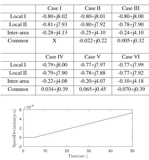
Table 1.2: System Rotor-Speed Modes for Hydro-Dominated System Case I Case II Case III Local I -0.80+j8.02 -0.80+j8.01 -0.80+j8.00 Local II -0.81+j7.93 -0.80+j7.92 -0.78+j7.90 Inter-area -0.28+j4.13 -0.25+j4.10 -0.24+j4.10 Common X -0.022+j0.22 0.005+j0.32
Case IV Case V Case VI Local I -0.79+j8.00 -0.77+j7.97 -0.77+j7.99 Local II -0.79+j7.90 -0.78+j7.88 -0.77+j7.92 Inter-area -0.22+j4.08 -0.20+j4.07 -0.10+j4.18 Common 0.034+j0.39 0.065+j0.45 -0.070+j0.39
Figure 1.4: System speed for Case I: no turbine governor
1.5.1 I
MPACT OFH
YDRO-T
URBINES
PEED-G
OVERNING Consider a turbine-governor (TG) model depicted in Fig. 1.5.0 Tmax Porder Wref Speed Pmech s sT 1 1 c sT sT 1 1 3 5 4 1 1 sT sT R 1
Figure 1.5: A simplified turbine-governor model.
Thus, the transfer function between the speed and mechanical power is defined, ∆𝑃𝑚(𝑠)
∆𝜔(𝑠) = −𝐺𝑡𝑔(𝑠) =
−(1 + 𝑠𝑇3)(1 + 𝑠𝑇4)
𝑅(1 + 𝑠𝑇𝑠)(1 + 𝑠𝑇𝑐)(1 + 𝑠𝑇5) (1.10) A set of parameters are selected for (1.10) to represent a hydro-type TG, as listed in Table 1.3.
19
Table 1.3: Parameters for A Hydro-Type TG R Ts Tc T3 T4 T5 0.05 0.5 10 1 -1 0.5
The TG model is enabled on generator 1, the system rotor-speed modes are recalculated, and listed in Table 1.2 (Case II). It is seen that the common mode appears and is stable. The small load rejection is simulated, and the system speed variation is shown in Fig. 1.6. As can be seen, the system converges to a new synchronous reference, albeit experiences oscillation. The oscillation frequency is 0.035 Hz indicating the common mode dynamics. Since the loads are almost constant power, it is expected that the common mode dynamics would be mainly governed by the mechanical power modulation in accordance with (1.2). For verification purpose, the exciter and PSS are removed, the common mode is -0.0286 + j0.2169.
Figure 1.6: System speed for Case II. Single hydro-TG.
The Re{−𝐺𝑡𝑔(𝑓)} as well as Im{−𝐺𝑡𝑔(𝑓)} ( 𝐺𝑡𝑔(𝑓) denotes 𝐺𝑡𝑔(𝑠) evaluated at 𝑗2𝜋𝑓) over a continuous range of frequencies are plotted in Fig. 1.7 (a) and (b), respectively. It is seen that at the common mode frequency, the Re{−𝐺𝑡𝑔(𝑓)} is a negative number, which means a positive damping support in accordance with (9a). The Im{−𝐺𝑡𝑔(0.035)} is a positive number of a significant value. The common mode appears possibly because of this strong synchronizing torque support.
The same TG model is added on generator 2. The rotor-speed modes are altered (Table 1.2-Case III), especially the common mode becomes unstable. The small load rejection is simulated and the system speed variation is shown in Fig. 1.8. As can be seen,
20
the system failed to converge to a new synchronous reference. According to (9b), the oscillation frequency tends to increase on the basis of 0.035 Hz in the presence of additional Im{−𝐺𝑡𝑔(0.035)}. However, even though the total number of 𝐺𝑡𝑔(𝑓) is increased, the 𝐺𝑡𝑔(𝑓) falls at 0.051 Hz, as marked in Fig. 1.7 (a), consequently results in an un-damped common mode.
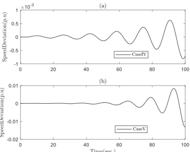
The TG model is added on generator 3 and 4 in sequence, the system rotor-speed modes are listed in Table 1.2 under Case IV and Case V, respectively. The system frequency response for both cases are plotted in Fig. 1.9 (a) and (b), respectively. As observed in the former case, the common mode frequency becomes larger and larger; meanwhile the mode becomes more and more unstable.
Figure 1.7: Real and imaginary parts for −𝐺𝑡𝑔(𝑓).
21
Figure 1.9: System speed for Case IV and Case V. Three and four hydro-TGs respectively.
It is noted that the inter-area mode damping is reduced. As can be seen in Fig. 1.7 (a), the TG has negative damping torque support around the inter-area mode frequency thus degrading the mode damping in accordance with the energy-flow theory in [24] and its frequency domain representation in [25]. The decrease of the inter-area mode frequency seems to be attributed to the TG’s negative synchronizing torque support around the mode frequency.
1.5.2 I
MPACT OFS
TEAM-T
URBINES
PEED-G
OVERNINGA set of parameters for (1.10) is considered to represent the turbine-governor as a steam-type, the parameters are listed in Table 1.4. The Re{−𝐺𝑡𝑔(𝑓)} and Im{−𝐺𝑡𝑔(𝑓)} over a continuous range of frequencies are plotted in Fig. 1.10 (a) and (b), respectively.
Table 1.4: Parameters for A Steam-Type TG R Ts Tc T3 T4 T5 0.05 0.5 10 3 0 0.05
22
Significant difference between the steam-type TG and the hydro-type TG is observed that is, in the very low frequency band (say below 0.1 Hz), the Re{−𝐺𝑡𝑔(𝑓)} maintains negative. Enabling the TG model on generators by following the same procedure as done in the last sub-section. The system rotor-speed modes are calculated and listed in Table 1.5. It can be seen the common mode frequency increases as the Im{−𝐺𝑡𝑔(𝑓)} adds in. Even though the larger mode frequency results in smaller individual Re{−𝐺𝑡𝑔(𝑓)} (see Fig. 1.10 (a)), the increased total number of Re{−𝐺𝑡𝑔(𝑓)} tends to accumulate a bigger damping factor for the mode. The frequency response for the four cases are plotted in Fig. 1.11. It clearly shows that the frequency response is much improved because of the damping characteristic of the steam-type TG. Moreover, more speed-governing results in smaller system speed bias from the original synchronous reference. However, this common grid-code may encounter difficulties when the hydro-type TG is dominant in the system (as observed in [1,4]), which can be inferred from the simulation studies in the last sub-section. On the other hand, the system is usually required to respond fast enough to compensate the power imbalance; this requires the common mode frequency should not be too small; again this requirement is unfavorable for the hydro-dominated system. As shown in [3], for the turbine equipped with PID-type governor, careful tuning of the PID parameters may guarantee the TG’s damping contribution to the common mode under various loading conditions. Nevertheless, it remains to be seen if such settings are adequate in islanded conditions, which are the recommended scenario for validating governor settings [4].
For the steam TG scenario, the speed-governing has almost no influence on the inter-area mode damping, as the TG creates trivial damping torque around the mode frequency (see Fig. 1.10 (a)). It is true that the actual turbine-governor usually exhibits non-linearity, the impact of turbine-governor on the electro-mechanical oscillations may be complicated [26]. In addition, a strong adverse coupling between governor dynamics and low-frequency inter-area modes has been found in other studies [27] while acceleration power based PSS has been shown to influence the damping of the common mode adversely [8].
23
Figure 1.10: Real and imaginary parts for −𝐺𝑡𝑔(𝑓).
Figure 1.11: System speed for the steam TG scenarios. One, two, three and four steam TGs.
1.5.3 I
MPACT OFL
OADV
OLTAGES
ENSITIVITYStudies in [10] demonstrated that the load voltage sensitivity could play important role in shaping the common mode dynamics. Readers are also referred to [11] for the theoretical justification on the coupling of active power-speed and reactive power-voltage channels. The following analytical assessments aim to verify the conjecture and taking advantage of the disaggregation of the eigenvalue, where to enable and monitor the damping controls for the common and inter-area modes based on load voltage sensitivity are explained as well.
24
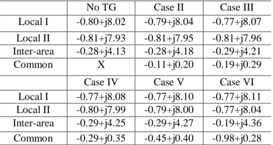
Table 1.5: System Rotor-Speed Modes for Steam-Dominated System No TG Case II Case III Local I -0.80+j8.02 -0.79+j8.04 -0.77+j8.07 Local II -0.81+j7.93 -0.81+j7.95 -0.81+j7.96 Inter-area -0.28+j4.13 -0.28+j4.18 -0.29+j4.21 Common X -0.11+j0.20 -0.19+j0.29
Case IV Case V Case VI Local I -0.77+j8.08 -0.77+j8.10 -0.77+j8.11 Local II -0.80+j7.99 -0.79+j8.00 -0.77+j8.04 Inter-area -0.29+j4.25 -0.29+j4.27 -0.19+j4.36 Common -0.29+j0.35 -0.45+j0.40 -0.98+j0.28
For the load composition in the previous cases, ∆𝑃𝐿 will be trivial during the speed variations. However, if we increase the percentage of constant impedance load in the load composition, the loads will significantly participate in the frequency response [10]. The modified load composition is listed in Table 1.6.
Table 1.6: Load Composition: Mixed Constant Power and Constant Impedance Loads Constant P Constant I Constant Z Bus 4 50% 1% 49% Bus 14 50% 1% 49% Bus 101 80% 0 20%
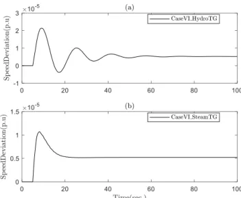
The new load composition is enabled on the Case V in the hydro and steam TG scenarios, respectively. The system rotor-speed modes under this load model condition are listed in Table 1.2 and Table 1.5 under Case VI, respectively. The frequency response for the two cases are plotted in Fig. 1.12 (a) and (b), respectively.
25
Figure 1.12: System speed for the new load composition scenarios.
An immediate observation is that the common mode frequency is reduced while its damping factor is much improved. However, for the hydro-TG scenario, the common mode frequency decreases to 0.062-Hz which still results in a negative damping torque support from the TGs (see Fig. 1.7 (a)). Therefore, there should be additional damping source present, to ascertain this, attention should be given to the load dynamics in accordance with (1.2). The polynomial load model for load j can be mathematically represented as
𝑃𝐿,𝑗 = 𝑃𝐿0,𝑗[𝑎1(𝑉𝐿,𝑗 𝑉𝐿0,𝑗 ) 2 + 𝑎2(𝑉𝐿,𝑗 𝑉𝐿0,𝑗 ) + 𝑎3] (1.11) where 𝑉𝐿,𝑗 is the terminal voltage seen at the load-transmission interconnection point, 𝑉𝐿0,𝑗 is the nominal voltage, 𝑃𝐿0,𝑗 is the nominal active-power consumption of the load, and 𝑎1+ 𝑎2+ 𝑎3 = 1. The linearization of (1.11) will define the small-signal dynamics of the voltage dependent load in a decoupled manner,
∆𝑃𝐿,𝑗 =𝑃𝐿0,𝑗(2𝑎1+ 𝑎2)
𝑉𝐿0,𝑗 ∆𝑉𝐿,𝑗 (1.12) For a particular mode oscillation, decomposing the load power deviation with respect to the deviation of load bus speed ∆𝜔𝐿,𝑗 as done in (1.3b) and (1.6), the damping and
26
synchronizing torque coefficients for the ZIP loads are
𝐾𝐷,𝑗 = Re {𝜑𝑉𝐿,𝑗 𝜑𝜔𝐿,𝑗 }𝑃𝐿0,𝑗(2𝑎1+ 𝑎2) 𝑉𝐿0,𝑗 (1.13𝑎) 𝐾𝑆,𝑗 = −Im {𝜑𝑉𝐿,𝑗 𝜑𝜔𝐿,𝑗} 2𝜋𝑓𝑃𝐿0,𝑗(2𝑎1+ 𝑎2) 𝜔𝑠𝑉𝐿0,𝑗 (1.13𝑏) where 𝜑𝑉𝐿,𝑗
𝜑𝜔𝐿,𝑗 denotes the relative mode observability seen by the bus voltage and bus speed
for load j. Denoting 𝐺𝑉𝐿,𝑗𝜔𝐿,𝑗(𝑓) = ∆𝑉𝐿,𝑗(𝑗2𝜋𝑓)
∆𝜔𝐿,𝑗(𝑗2𝜋𝑓), since the common mode governs all the bus
frequencies oscillating coherently, according to (1.9a) and (1.9b), 𝐺𝑉𝐿,𝑗𝜔𝐿,𝑗(𝑓) is examined to find out the participation of voltage dependent loads in the small-signal frequency dynamics. An ambient-condition simulation is carried out for the Case VI in the hydro-type TG scenario, a small percentage of load power are modelled as random, a 10-min data set is used for analysis, the 𝐺𝑉𝐿𝜔𝐿(𝑓) for bus 14 is estimated using periodogram [28], and shown in Fig. 1.13. As a result, positive Re{𝐺𝑉𝐿𝜔𝐿(𝑓)} in the very low frequency band is observed, which implies that the load tends to add damping to the common mode in accordance with (1.9a) and (1.13a); the positive Im{𝐺𝑉𝐿𝜔𝐿(𝑓)} means that the additional synchronizing torque
introduced by the load tends to reduce the mode frequency in accordance with (1.9b) and (1.13b). The bus 4 exhibits almost the same 𝐺𝑉𝐿𝜔𝐿(𝑓) in the very low frequency band, thus not shown here.
An example is given to see how the transfer functions of the system components evaluated in the frequency domain reflect the eigenvalue solution. Considering equation (1.1) in the machine base (900 MVA), and considering the equivalent inertia 𝐻 = 4 × 5 = 20, according to Fig. 1.7 (a), at the common mode frequency, ∑ ∆𝑃𝐺,𝑖(𝑗2𝜋𝑓)
∆𝜔(𝑗2𝜋𝑓) 𝑚
𝑖=1 = 0.7251 × 4 =
2.9, considering 𝑉𝐿0,𝑗 ≈ 1(in the system base (100 MVA)), according to Fig. 1.13 (a) and eq. (13a), ∑ ∆𝑃𝐿,𝑗(𝑗2𝜋𝑓)
∆𝜔(𝑗2𝜋𝑓) 𝑛
𝑗=1 = (3.5 × 9.76 × (2 × 0.5))/9 + (3.5 × 14.63 × (2 × 0.5))/9 =
9.5, the damping factor given by (9a) is: 𝜎 =2.9−9.5
27
Fig. 1.13 (b), eq. (13b), and eq. (9b), 𝑓 ≈ [5.484 × 4 −(2.3×9.76×(2×0.5))
9 −
(2.3×14.63×(2×0.5))
9 ] /(20 × 4𝜋) = 0.06 . It is seen that the large voltage dependent load
naturally has bigger influence on the common mode. It should be noted that the computation is found less accurate when the damping factor is large such as the Case V and VI in the steam-TG scenario. However, for the system, which is easily exhibiting oscillatory in the primary frequency response, the torque coefficient spectra of relevant components may be a convenient choice for quantitatively studying the performance of common frequency controls.
Figure 1.13: Real and imaginary parts for 𝐺𝑉𝐿𝜔𝐿(𝑓) in the range of 0.01-0.1 Hz. Case VI with hydro-TGs.
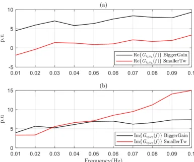
To further verify that the speed-voltage coupling affects the common mode dynamics in the presence of voltage dependent load, two more cases on the basis of Case VI in the hydro-TG scenario are considered: (1). the PSS gain is tuned from 20 to 40, the common mode becomes -0.15+j0.29; (2). the PSS washout time constant is tuned from 5 to 1, the common mode becomes -0.02+j0.29. The Re{𝐺𝑉𝐿𝜔𝐿(𝑓)} and Im{𝐺𝑉𝐿𝜔𝐿(𝑓)} for bus 14 for the two cases are shown in Fig. 1.14 (a) and (b) respectively, it is seen that the variation of the speed-voltage relation dictated the change of common mode.
28
Figure 1.14: Real and imaginary parts for 𝐺𝑉𝐿𝜔𝐿(𝑓) in the range of 0.01-0.1 Hz. Case VI with hydro-TGs (Bigger PSS gain and smaller washout time constant cases).
On the other hand, the impact of load voltage sensitivity on the common mode can also be viewed from the modal controllability (or say eigenvalue sensitivity for this mode) seen by the exciter voltage reference of the synchronous machines. As an example, for the Case V in the hydro-TG scenario, the common mode controllability seen by the exciter voltage reference of generator 4 is only 0.55, while for Case VI, the value jumps to 32.48, however, for generator 1, which is electrically further away from the largest load, the common mode controllability increases to 6.75 only.
Another observation from the Case VI in the hydro-TG scenario is that the inter-area mode damping is drastically reduced in the presence of voltage dependent loads. The reason is given as follows by leveraging the classical mode shape analysis [20] and an extended version of the energy-flow theory [24]. Considering the unit (4 generation units and 2 large loads) connected to each of the a.c. buses as rotating mass, using the ambient data set, the observability of the low frequency speed modes given by the estimated power spectral density (PSD) are shown in Fig. 1.15, as seen, the coherent peak at 0.06 Hz corresponds to the common mode, and the units at bus 11, 12, and 14 are much more observable for the inter-area mode, this is possibly because the system is sending power from the left-side to
29
the right side, considering the synchronous machine parameters are the same, the center-of-inertia is likely located on the left side of the system. The local modes are not observable in the spectra for this ambient dada set, possibly due to the high damping of the modes and/or the low controllability seen by the load power channels comparatively to the common and inter-area modes. The relative phase for the bus frequencies in the range of 0.1-1 Hz given by the estimated cross-power spectral density are shown in Fig. 1.16, it clearly shows that for the inter-area mode, the units at bus 1, 2, and 4 swing against with the units at bus 11, 12, and 14.
Figure 1.15: Estimated PSD spectra for the bus frequencies. Case VI for hydro-TGs.
Figure 1.16: Estimated relative phase for the bus frequencies. Case VI for hydro-TGs.
The electromechanical mode damping factor is approximately inversely proportional to the total oscillation energy dissipation ability of the system components [24] because of the mode’s small damping factor and fast oscillation frequency nature (the necessary
![Figure I.2: Deployment of phasor measurement units in the North American power grid (credit: NASPI [70])](https://thumb-eu.123doks.com/thumbv2/123doknet/2883821.73254/15.918.175.761.178.607/figure-deployment-phasor-measurement-north-american-credit-naspi.webp)