HAL Id: pastel-00873162
https://pastel.archives-ouvertes.fr/pastel-00873162
Submitted on 15 Oct 2013
HAL is a multi-disciplinary open access
archive for the deposit and dissemination of sci-entific research documents, whether they are pub-lished or not. The documents may come from teaching and research institutions in France or abroad, or from public or private research centers.
L’archive ouverte pluridisciplinaire HAL, est destinée au dépôt et à la diffusion de documents scientifiques de niveau recherche, publiés ou non, émanant des établissements d’enseignement et de recherche français ou étrangers, des laboratoires publics ou privés.
Bojan Joveski
To cite this version:
Bojan Joveski. Semantic multimedia remote viewer for collaborative mobile thin clients. Other [cs.OH]. Ecole Nationale Supérieure des Mines de Paris, 2012. English. �NNT : 2012ENMP0100�. �pastel-00873162�
T
T
H
H
E
E
S
S
École doctorale n°432: Sciences des Métiers de l'Ingénieur
Jury
M. Michel JOURLIN, Professeur, LHC UMR CNRS, Université de Saint-Etienne Rapporteur M. Touradj EBRAHIMI, Professeur,MSP , Swiss Federal Institute of Technology Rapporteur M. Jean-Noël PATILLON, PhD, DTSI, CEA Saclay Examinateur M. Bart DHOEDT, Professeur, IBCN, Ghent University - iMinds Examinateur M. Najah NAFFAH, PhD, Executive director, Prologue Examinateur Mme. Françoise PRETEUX,Professeur, Direction des Recherches, Mines ParisTech Examinateur M. Mihai MITREA, HDR, ARTEMIS, Mines-Telecom, Telecom SudParis Examinateur M. Ian James MARSHALL, Chef cellule d'innovation, Prologue Invité
T
H
È
S
E
Directeur de thèse : Françoise PRETEUX Co-directeur de thèse : Mihai MITREA
présentée et soutenue publiquement par
Bojan JOVESKI
le 18 Décembre 2012
Dispositif de rendu distant multimédia et sémantique
pour terminaux légers collaboratifs
Doctorat ParisTech
T H È S E
pour obtenir le grade de docteur délivré par
l’École nationale supérieure des mines de Paris
Spécialité “Informatique temps réel, robotique et automatique”
I dedicate this thesis to my wife Mladena, for being my pillar, my joy and my guiding light.
Acknowledgments
I am deeply indebted to my thesis director Professor Françoise Prêteux, for giving me an opportunity to work in this challenging research topic as part of the ARTEMIS department at Institut Mines Telecom, Telecom SudParis, and as PhD student at the CAOR department at MINES ParisTech. I thank her not only for the academic support but also for promoting and supporting me in the world of MPEG standardization.
I would like to express my sincere gratitude to my thesis co-director HDR Mihai Mitrea, who offered his continuous advice and encouragement throughout the course of this thesis. I thank him for the systematic guidance, great effort he put into training me in the scientific field, good teaching, good company and lots of good ideas. Without him this thesis would not have come to a successful completion with his continuous support and help to remain focused for achieving my goal.
I am grateful to Professor Michel Jourlin at Laboratoire Hubert Curien, Université Jean Monnet Saint-Etienne and Professor Touradj Ebrahimi at MSP Group, Swiss Federal Institute of Technology (EPFL), for granting me the honor and accept the task of reviewing this thesis. I thank them for their precious comments and suggestions for its amelioration and perspectives of this work. I would also like to thank Professor Bart Dhoedt at INTEC-IBCN, Ghent University for the collaborative work, evaluation of the thesis and the honor of presiding the jury. I would also like to thank PhD Jean-Noël Patillon at CEA LIST and PhD Najah Naffah, Executive director at Prologue SA, for the time they spent in the evaluation of the thesis with thoughtful comments and advices for the future of this work in the industry field.
I would like to express my sincere thanks to Iain-James Marshall, Responsible for the innovation unit at Prologue SA, for generously sharing his time in our cooperative MPEG work and for accepting this thesis as part of the jury. Many thanks for his native English language support that helped me improve my language skills.
I thank Professor Arnaud De La Fortelle, director of the CAOR department and Professor François Goulette, coordinator of the thesis program at CAOR, for welcoming me at MINES ParisTech and for their valuable feedback provided during my mid-term presentation.
I thank Mrs. Evelyne Taroni at ARTEMIS Department, Institut Mines Telecom, Telecom SudParis, Mrs. Christine Vignaux at CAOR, MINES ParisTech and Mrs. Sylvie Barizzi-Loisel at MINES ParisTech for their patience and valuable help in the administration matters.
My colleagues Ludovico Gardenghi and Rama Rao Ganji, deserve a special mention. I thank them for helping me with their software development skills and their availability during this thesis. I thank PhD Pieter Simoens at Ghent University and Abdeslam Taguengayte, Research and Development Team Manager at Prologue SA, for our cooperative research work, reported in several publications.
Special thanks to my colleagues: Margarete Ortner, Afef Chammem and Adriana Garboan, for their understanding and generous help not only as colleagues but also as friends. I thank them for the positive spirit they brought in all these years.
Last but not least, I wish to take this opportunity to thank my parents, who raised me, taught me, and loved me and to my brother Filip for his intellectual and motivational discussions and emotional support throughout my academic career.
Abstract
In accordance with current day user expectancies, no functional discrepancies should be noticeable between mobile thin client and fixed desktop applications.
The thin client paradigm covers all the scientific, technical and applicative issues related to a terminal (desktop, PDA, smartphone, tablet) essentially limited to I/O devices (display, user pointer, keyboard) and with its all computing and storage resources located on a remote server farm. This model implicitly assumes the availability of a network connection (be it wired or wireless) between the terminal and the computing resources.
From the architectural point of view, the thin client paradigm can be accommodated by a client-server model, where the client is connected to the server through a connection managed by a given protocol. From the functional point of view, the software application (text editing, www browsing, multimedia entertainment, …) runs on the server and generates some semantically structured graphical output (i.e. a collection of structured text, image/video, 2D/3D graphics, …). This graphical content should be transmitted and visualized by the client, where the user interactivity is captured and sent back to the server for processing.
The term remote viewer refers to all software modules, located at both end points (server and client), making possible the graphical content generated by the server to be displayed at the client side and the subsequent user events to be sent back to the server, in real time.
Figure 1. Multimedia remote viewer
Defining of a multimedia remote viewer for mobile thin clients remains a challenging research topic, coming across with threefold scientific/technical constraint relating to the user expectancies, the underlying mobile environment issues and the market acceptance. First, on the user expectancies side, the remote viewer should provide at the client side heterogeneous multimedia content and the support for ultimate collaboration functionalities. Second, from the mobility point of view, issues related to the network (arbitrarily changing bandwidth conditions, transport errors, and latency) and to the terminal (limitations in CPU, storage, and I/O resources)
should be addressed. Finally, the market acceptance of such a solution depends on its ability of featuring terminal independency and of benefiting from community support.
Current day remote viewer solutions for mobile thin clients are inherited from wired environments, where several reference technologies are available for decades: X, VNC, NX, RDP, to mention but a few. Regardless of its original type, the heterogeneous graphical content (text, image, graphics, video, 3D, …) generated by the server is converted into sequences of images (eventually a mixture of images and graphics), which are then interactively displayed by the client. Such an approach would appear to be inappropriate when addressing the above-mentioned mobile thin client constraints. First, it prevents the client from having a true multimedia experience and offers no support for collaboration (which is supposed to be solved by additional devoted mechanisms). Second, it considers the multimedia content adaptive compression solely from the particular point of view of image compression, thus resulting in sub-optimal network resource consumption. Finally, these solutions depend on the terminal hardware/software peculiarities, thus representing a pitfall for a standard deployment on the market.
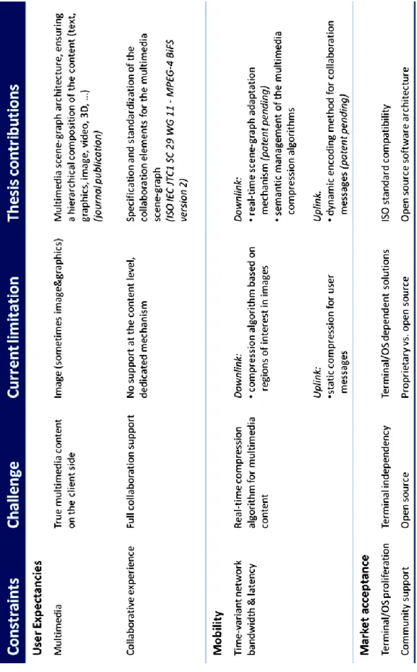
The present thesis follows a different approach and introduces a semantic multimedia remote viewer for collaborative mobile thin clients, see Table 1. The principle is based on representing the graphical content generated by the server as an interactive multimedia scene-graph, enriched with novel components for direct handling (at the content level) of the user collaboration. In order to cope with the mobility constraints, a semantic scene-graph management framework was design (patent pending) so as to optimize the multimedia content delivery from the server to the client, under joint bandwidth-latency constraints in time-variant networks. The compression of the collaborative messages generated by the users is done by advancing a devoted dynamic lossless compression algorithm (patented solution). This new remote viewer was evaluated incrementally by the ISO community and its novel collaborative elements are currently accepted as extensions for the ISO IEC JTC1 SC 29 WG 11 (MPEG-4 BiFS) standard.
The underlying software demonstrator, referred to as MASC (Multimedia Adaptive Semantic Collaboration), is implemented as open-source. The solution was benchmarked against its state-of-the-art competitors provided by VNC (RFB) and Microsoft (RDP).
It was demonstrated that: (1) it features high level visual quality, e.g. PSNR ranges between 30 and 42dB or SSIM has values larger than 0.9999; (2) the downlink band-width gain factors range from 2 to 60 while the up-link bandwidth gain factors range from 3 to 10; (3) the network round-trip time is reduced by factors of 4 to 6; (4) the CPU activity is larger than in the Microsoft RDP case but is reduced by a factor of 1.5 with respect to the VNC RFB.
The MASC is evaluated for its potential industrialization in various applicative fields, such as application virtualization in the cloud (in partnership with Prologue), promoting collaborative decision making system for video surveillance applications (in partnership with CASSIDIAN) as well as virtual collaborative environment for medical assistance (in partnership with Philips HealthCare and Bull).
Table of contents
Acknowledgments ... iii
Abstract... vii
Table of contents ... xi
List of figures ... xiii
List of tables ... xv
List of code ... xvii
Chapter 1.
Introduction ... 1
1.1Context…… ... 2
1.1.1. Online social networking ... 2
1.1.2. Cloud computing ... 5
1.1.3. Bridging social networking and cloud computing ... 8
1.2Objectives ... 8
1.3Thesis structure ... 11
Chapter 2.
State of the art ... 13
2.1Content representation technologies ... 14
2.1.1. Introduction ... 14
2.1.2. Comparison of content representation technologies ... 15
2.1.3. BiFS and LASeR principles ... 17
2.1.4. Conclusion ... 24
2.2Mobile Thin Clients technologies ... 25
2.2.1. Overview ... 25
2.2.2. X window system... 25
2.2.3. NoMachine NX technology ... 28
2.2.4. Virtual Network Computing ... 30
2.2.5. Microsoft RDP ... 32
2.2.6. Conclusion ... 34
2.3Collaboration technologies ... 36
Chapter 3.
Advanced architecture ... 43
3.1Functional description ... 44 3.2Architectural design ... 46 3.2.1. Server-side components... 47 3.2.2. Client-side components... 60 3.2.3. Network components ... 62 3.3Conclusion ... 64Chapter 4.
Architectural benchmark ... 65
4.1Overview.. ... 66
4.2Experimental setup and results... 67
4.2.1. Visual quality ... 67
4.2.2. Down-link bandwidth consumption ... 70
4.2.3. User interaction efficiency ... 73
4.2.4. CPU activity ... 74
4.3Discussions ... 76
4.3.1. Semantic Controller performance ... 76
4.3.2. Pruner performance ... 77
Chapter 5.
Conclusion and Perspectives ... 79
5.1Conclusion ... 80 5.2Perspectives ... 81
List of abbreviations ... 85
References ... 87
Appendix I ... 91
Appendix II ... 93
Appendix III ... 95
List of publications ...117
List of figures
Figure 1. Multimedia remote viewer ... vii
Figure 1.1. Facebook popularity, registered active users during the period from 2004 till 2011 ... 3
Figure 1.2. YouTube popularity, videos viewed daily expressed in billions ... 3
Figure 1.3. Wikipedia articles submitted yearly from 2001 till 2012 ... 4
Figure 1.4. Total internet exchange in only 1 minute ... 4
Figure 1.5. Cloud computing at a glance ... 5
Figure 1.6. Active EC2 virtual machines grouped by operating system... 6
Figure 1.7. Total market share by operating systems in 2012 ... 6
Figure 1.8. Total market share by cloud computing solutions in 2011 ... 7
Figure 1.9. The workloads processed in the cloud will reach more than 50% by 2015 ... 7
Figure 1.10. The traffic exchanged in the cloud per year by 2015 (1 ZB = 270 Bytes) ... 7
Figure 1.11. Collaborative mobile thin clients: a new generation of mobile thin clients bridging the gap between the cloud computing and communitarian users ... 9
Figure 2.1. Scene technology support for mobile thin clients ... 14
Figure 2.2. Concurrent solutions for heterogeneous content encoding, updating and streaming ... 17
Figure 2.3. BiFS scene-graph description example ... 19
Figure 2.4. LASeR architecture ... 23
Figure 2.5. X windows system server-client architecture ... 25
Figure 2.6. X window system server and client side content rendering ... 26
Figure 2.7. NoMachine architecture ... 28
Figure 2.8. NX client-server rendering ... 29
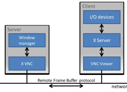
Figure 2.9. The VNC server-client architecture ... 30
Figure 2.10. VNC server-client content rendering ... 31
Figure 2.11. Windows RDP server-client architecture ... 32
Figure 2.12. Microsoft RDP server-client content rendering ... 33
Figure 2.13. Comparison of the current remote display solutions ... 35
Figure 2.14. The concept of real-time user collaboration ... 36
Figure 2.15. Creating a text document using the Google Docs... 37
Figure 2.16. World of Warcraft (WoW) screenshot ... 38
Figure 2.17. Video streaming on YouTube using www browser ... 39
Figure 2.18. Video conferencing using Skype ... 39
Figure 3.1. State-of-the-art architectural framework for mobile thin client remote display ... 44
Figure 3.3. Detailed architectural framework ... 46
Figure 3.4. Flowchart for image management ... 50
Figure 3.5. The Pruning mechanism, exemplified for image content ... 52
Figure 3.6. Traditional scene-graph creation ... 52
Figure 3.7. Advanced scene-graph adaptively created ... 53
Figure 3.8. General architecture for collaborative scenes ... 57
Figure 3.9. Direct client to client collaboration by using the collaboration node ... 62
Figure 4.1. Illustration of the text editing application run on the server (a) and displayed on the mobile thin client, after its conversion into BiFS / MASC-BiFS (b) and MASC-LASeR (c) ... 68
Figure 4.2. Illustration of the www browsing application run on the server (a) and displayed on the mobile thin client, after its conversion into BiFS / MASC-BiFS (b) and MASC-LASeR (c) ... 68
Figure 4.3. Average bandwidth consumption (in KBytes) for text editing (gEdit), as a function of time ... 71
Figure 4.4. Average bandwidth consumption (in KBytes) for www browsing (Epiphany), as a function of the browsing step ... 71
Figure 4.5. The average maximum CPU consumption (in %) while browsing, as a function of the browsing step ... 75
Figure 4.6. Performance of the Semantic Controller block: total bandwidth consumption in the case of text editing over image type (encoding used for the images in the scene-graph) ... 76
Figure 4.7. Performance of the Semantic Controller block: total bandwidth consumption in the case of www browsing (executing the 9 steps) over image type (encoding used for the images in the scene-graph) ... 77
Figure 4.8. Average maximum CPU activity as a function of time expressed in seconds, in the text editing experiment ... 78
Figure 4.9. Average maximum CPU activity as a function of time expressed in seconds, in the www browsing experiment ... 78
Figure 5.1. Enablers for the advanced collaborative mobile thin client framework ... 80
Figure 5.2. Extension from Linux to Windows applications ... 83
List of tables
Table 1. Collaborative mobile thin clients: constraints, challenges, state of the art limitations and thesis
contributions ... ix
Table 1.1. Thesis objectives ... 10
Table 2.1. Current collaboration status ... 40
Table 2.2. Illustrations of the current limitations of the existing technologies ... 41
Table 3.1. Traditional MPEG-4 scene-graph processing ... 54
Table 3.2. Advanced scene-graph adaptation ... 55
Table 4.1. Visual quality evaluation for X to MPEG (BiFS, MASC-BiFS and MASC-LASeR) conversion ... 70
Table 4.2. Average overcharge traffic (in KB) induced by network disconnection, for text editing ... 73
Table 4.3. Average overcharge traffic (in KB) induced by network disconnection, for www browsing. ... 73
List of code
Code 2.1. Example of BiFS scene-graph, represented using VRML ... 22
Code 2.2. LASeR scene example of the Figure 4.3, including SAF aggregation ... 24
Code 2.3. X Protocol request description, polySegment ... 27
Code 2.4. X Protocol request description, putImage ... 27
Code 2.5. X Protocol request description, polyText16 ... 27
Code 2.6. Code sample written in C languge, for compressing the polySegment X request ... 29
Code 2.7. Graphical primitive, used by VNC server ... 31
Code 2.8. VNC HEXTILE encoding function expressed in C language ... 31
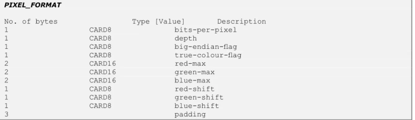
Code 2.9. VNC PIXEL FORMAT encoding function expressed in C language... 32
Code 2.10. Binary description of an RDP rectangle message ... 33
Code 2.11. Binary description of an RDP image pixel message... 34
Code 3.1. X Protocol description of polyRectangle syntax... 48
Code 3.2. Syntax of parsing polyRectangle by the XParser ... 48
Code 3.3. XML description of BiFS conversion of a rectangle ... 49
Code 3.4. SVG description of LASeR conversion of a rectangle ... 49
Code 3.5. Part of the C language code enriching the scene-graph with JavaScript functionality for mouse click ... 57
Code 3.6. Technical description of the CollaborationNode ... 58
Chapter 1. Introduction
Tout d’abord, ce chapitre introduit les définitions liées au paradigme du terminal léger et identifie le rôle que les systèmes de rendu distants jouent dans un tel cadre, ainsi que leur limitations en enjeux. Ensuite, les principales contributions de la thèse sont succinctement présentées. Finalement, la structure de la thèse est précisée.
1.1 Context
In August 2008, the number of users accessing various online social networks stayed quite modest (Facebook – 100 million, MySpace – 300 million, Tweeter – 5 million), the number of mobile connected Internet users did not reached yet the limit of 150 million and cloud computing was rather a concept then a business per-se (Google Apps and Web 2.0 just emerged on the market). Nowadays, Facebook approaches the 1 billion users threshold, 6 billion of mobile devices are Internet connected and cloud computing generates 109 billion of dollars in revenue a year, [Gartner, 2012].
By 2020, the social networking will cover 70% of the Earth population, number of mobile connected Internet devices will be multiplied by 2 and the cloud computing revenue by 3, [GSMA, 2012].
However, despite the synchronicity in their explosive development, the on-line networking and cloud computing revolutions followed different ways.
1.1.1. Online social networking
Social networking, also referred to as social Internet media, encompasses the Internet-based tools that make easier for connected users to share (watch, listen and interact with) any type of multimedia content.
Internet leverages the social networking to the level of becoming the most intensive business and marketing platform. Individual users, powered by heterogeneous mobile/fixed terminals, benefiting from the open standards open source software, aggregate themselves into online social networking in order to collaboratively enjoy a new type of multimedia experience.
Nowadays, 9 billion of devices are connected to Internet and their number is forecasted to reach 24 billion by 2020 [GSMA, 2011].
In order to answer to the interests of the all online communities, plenty of online tools are currently supporting social networking: Facebook, Youtube, mySpace, Flickr, Google+, Hi5, Tweeter.
Launched in February 2004, with the initial idea of exchanging information between the connected users, in just a couple of years it served several million of users. By offering to the users the possibility to exchange images, audio, video, and text, Facebook represents today the world most exploited social network, registering 950 million of online users. In only one minute, 135 000 photos are uploaded, 75 000 events are created and 100 000 demands for user
interconnections are sent [Facebook, 2012], see Figure 1.1. This huge amount of information brings to light the need for intelligent cloud computing platforms.
A ct iv e u se rs (i n m ill ions ) Year
Figure 1.1. Facebook popularity, registered active users during the period from 2004 till 2011
YouTube
The challenge to enable the online users to share their videos trough Internet was achieved by YouTube in 2005: online users can upload, share and comment their videos. This simple, still novel at that time online tool, has been very easy exploited by millions of users since then. Today, 72 hours of video are upload each minute, more than 4 billion hours of videos are watched per month by 800 million visits (per month) [Youtube, 2012], see Figure 1.2.
Figure 1.2. YouTube popularity, videos viewed daily expressed in billions
Wikipedia
Founded in 2001, Wikipedia becomes the nonprofit multilingual internet encyclopedia, translated in 285 languages. With the help of 100 000 active contributors, it accommodates 23 million articles, and serves the online users with more than 2.7 billion monthly page views, [Wikipedia, 2012], see Figure 1.3.
Figure 1.3. Wikipedia articles submitted yearly from 2001 till 2012
Conclusion
These basic three examples, although different by their finality, exemplify the social networking main characteristics:
a continuous grow, by registering each day new users and by involving existing users in new experiences;
although the social networking tools are continuously updated/replaced/changed, the user social interest remains;
the exchanged data reaches more than 650TB a minute (out of the total of 2025 TB exchanged in Internet each minute), see Figure 1.4, [Intel, 2012].
Under this framework, cloud computing positioned itself as very appealing solution for an intelligent and powerful data management system for social networking data in particular and for any type of data in Internet, in general.
1.1.2. Cloud computing
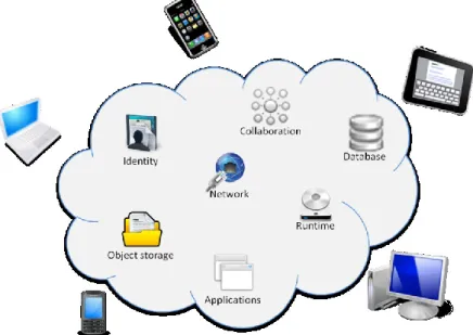
With the release of the “Elastic Compute Cloud” by Amazon (2006), “Microsoft Azure” by Microsoft (2010), and “Open Cloud Computing Interface” by Open Source community (2010) the new era of cloud computing platforms was started. These huge industrial supports raised the cloud computing to the ultimate working environment, where proprietary software applications (Office, Photoshop, 3D Max, …), running under their traditional OS (Microsoft Windows, Apple Lion, Linux Ubuntu, …) would give the user access to any kind of Big data (documents, photography/video archives, medical records, …), see Figure 1.5.
Figure 1.5. Cloud computing at a glance
Amazon cloud
Elastic Compute Cloud (EC2) released by Amazon for a limited public in 2006, is one of the first virtual computing environments allocating the hardware resources dynamically, allowing the online users to rent virtual computers by using Internet.
Today EC2 is capable to manage a large variety of operating systems, load custom applications, manage network access permissions and run software in real-time, according to the users requirements. It accommodates more then 46 000 active virtual machines, running multiple OSs, Figure 1.6. It can be seen that the various Linux distributions (Ubuntu, Linux, RedHat, Debian, Fedora,…) cover more than 80% of them.
Figure 1.6. Active EC2 virtual machines grouped by operating system
Microsoft cloud
With the release of Windows Azure in 2010, Microsoft offered to the users a cloud computing platform to build, deploy and manage applications. As nowadays the Microsoft Windows OS dominates the local setups application environments (more than 84% from the total, [Market, 2012]), Windows Azure has a huge potential in future exploitations, see Figure 1.7.
Figure 1.7. Total market share by operating systems in 2012
VMware cloud
In 2008 VMware announced an integrated solution for building and managing a complete cloud infrastructure. By the middle of 2009 VMware releases the vSphare 4, leveraging addition of virtual disks and on the fly. This solution provides all infrastructure services necessary to make workloads operational in minutes. By offering to these services, vSphere of VMware becomes the most distributed tool by 2011 having 89% of the market share, see Figure 1.8.
Figure 1.8. Total market share by cloud computing solutions in 2011
Conclusion
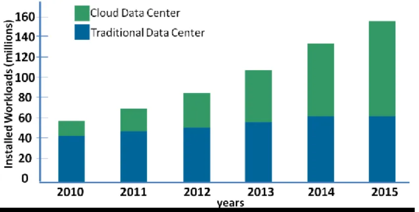
This migration from fixed setups to cloud is expected to grow in the very next years, see Figure 1.9 and Figure 1.10: by 2015, more than 50 percent of all processing workloads will take place in the cloud, and the data exchange will reach 4.8 Zettabytes, [Cisco, 2012].
Figure 1.9. The workloads processed in the cloud will reach more than 50% by 2015
1.1.3. Bridging social networking and cloud computing
The gap between social networking and cloud computing can be bridged by developing remote viewer solutions.
In the widest sense, the thin client paradigm refers to a terminal (desktop, PDA, smartphone, tablet) essentially limited to I/O devices (display, user pointer, keyboard), with all related computing and storage resources located on a remote server farm. This model implicitly assumes the availability of a network connection (be it wired or wireless) between the terminal and the computing resources.
Within the scope of this thesis, the term remote display refers to all the software modules, located at both end points (server and client), making possible, in real time, for the graphical content generated by server to be displayed on the client end point and for subsequent user events to be sent back to the server. When these transmission and display processes consider, for the graphical content, some complementary semantic information (such as its type, format, spatio-temporal relations or usage conditions to mention but a few) the remote display then becomes a semantic remote display1.
Our study brings to light the potential of multimedia scene-graphs for supporting semantic remote displays. The concept of the scene-graph emerged with the advent of the modern multimedia industry, as an attempt to bridge the realms of structural data representation and multimedia objects. While its definition remains quite fuzzy and application dependent, in the sequel we shall consider that a scene-graph is [BiFS, 2006]: “a hierarchical representation of audio, video and graphical objects, each represented by a […] node abstracting the interface to those objects. This allows manipulation of an object’s properties, independent of the object media.” Current day multimedia technologies also provide the possibility of direct interaction with individual nodes according to user actions; such a scene-graph will be further referred to as an interactive multimedia scene-graph.
In order to allow communitarian users to benefit from the cloud computing functionalities, a new generation of thin clients should be designed. They should provide universal access (any device, any network, any user …) to virtual collaborative multimedia environments, through versatile, user-friendly, real time interfaces based on open standard and open source software tools.
1.2 Objectives
The main objectives when developing a mobile thin client framework is to have the same user experience as when using a fixed desktop applications, see Figure 1.11.
1 The usage of the word semantic in this definition follows the MPEG-4 standard specification [BiFS, 2006] and the principles in some
related studies [Asadi, 2005], [Izquierdo, 2003].
2
Although the scene elements are structured in a tree, the standard name is the scene-graph.
Figure 1.11. Collaborative mobile thin clients: a new generation of mobile thin clients bridging the gap between the cloud computing and communitarian users
Under this framework, the definition of a multimedia remote display for mobile thin clients remains a challenging research topic, requiring at the same time a high performance algorithm for the compression of heterogeneous content (text, graphics, image, video, 3D, …) and versatile, user-friendly real time interaction support [Schlosser,2007], [Simoens, 2008]. The underlying technical constraints are connected to the network (arbitrarily changing bandwidth conditions, transport errors, and latency), to the terminal (limitations in CPU, storage, and I/O resources), and to market acceptance (backward compatibility with legacy applications, ISO compliance, terminal independence, and open source support).
The present thesis introduces a semantic multimedia remote viewer for collaborative mobile thin clients, see Table 1.1. The principle consists of representing the graphical content generated by the server as an interactive multimedia scene-graph enriched with novel components for directly handling (at the content level) the user collaboration. In order to cope with the mobility constraints, a semantic scene-graph management framework was design (patent pending) so as to optimize the multimedia content delivery from the server to the client, under joint bandwidth-latency constraints in time-variant networks. The compression of the collaborative messages generated by the users is done by advancing a devoted dynamic lossless compression algorithm (patented solution). This new remote viewer was incrementally evaluated by the ISO community and its novel collaborative elements are currently accepted as extensions for ISO IEC JTC1 SC 29 WG 11 (MPEG-4 BiFS) standard [BiFS, 2012].
Table 1.1. Thesis objectives
Constraints Challenge
User Expectancies
Multimedia True multimedia content on the client side
Collaborative experience Full collaboration support Mobility
Time-variant network bandwidth & latency
Real-time compression algorithm for multimedia content Market acceptance
Terminal/OS proliferation Terminal independency
1.3 Thesis structure
The thesis structure is divided in three main chapters.
Chapter 2 represents threefolded analysis of the state-of-the-art technologies encompassed by the remote viewers. In this respect, Section 2.1 investigates the use of multimedia content when designing a remote viewer. The existing technologies are studied in terms of binary compression, dynamic updating and content streaming. Section 2.2 considers the existing wired or wireless remote viewing solutions and assess their compatibility with the challenges listed in Table 1.1. Section 2.3 brings to light the way in which the collaborative functionalities are currently offered. This chapter is concluded, in Section 2.4, by identifying the main state-of-the-art bottlenecks in the specification of a semantic multimedia remote viewer for collaborative mobile thin clients. By advancing a novel architectural framework, Chapter 3 offers a solution in this respect. The principle is presented in Section 3.1, while the details concerning the architectural design are presented in Section 3.2. In this respect, the main novel blocks are: XGraphic Listener, XParser, Semantic MPEG-4 Converter, Semantic Controller, Pruner, Semantic Adapter, Interaction Enabler, Collaboration Enrichment, Collaboration and Interaction Event Manager and Collaboration and Interaction Handler.
Chapter 3 is devoted to the evaluation of this solution, which was benchmarked against its state-of-the-art competitors provided by VNC (RFB) and Microsoft (RDP). It was demonstrated that: (1) it features high level visual quality, e.g. PSNR values between 30 and 42dB or SSIM values larger than 0.9999; (2) the downlink band-width gain factors range from 2 to 60 while the up-link bandwidth gain factors range from 3 to 10; (3) the network roundtrip-time is reduce by factors of 4 to 6; (4) the CPU activity is larger than in the Microsoft RDP case but is reduced by a factor of 1.5 with respect to the VNC RFB.
The Chapter 4 concludes the thesis and open perspectives for future work. The references and a list of abbreviations are also presented.
The manuscript contains three Appendixes. The first two present the detailed descriptions of the underlying patents, while Appendix III gives the conversion dictionary used for converting the XProtocol requests into their MPEG-4 BiFS and LASeR counterparts.
Chapter 2. State of the art
Ce chapitre donne un aperçu critique sur les solutions existantes pour instancier les systèmes de rendu distant sur les terminaux mobiles légers (X, VNC, NX, RDP, ...). Cette confrontation entre les limites actuelles et les défis scientifiques / applicatives met en exergue que : (1) une vrai expérience multimédia collaborative ne peut pas être offerte au niveau du terminal, (2) la compression du contenu multimédia est abordée d’un seul point de vue image statique, ainsi entraînant une surconsommation des ressources réseau; (3) l’inexistence d’une solution générale, indépendante par rapport aux particularités logicielles et matérielles du terminal, ce qui représente un frein au déploiement des solutions normatives.
Par conséquent, définir un système de rendu distant multimédia pour les terminaux légers et mobiles reste un fort enjeu scientifique avec multiples retombées applicatives. Tout d'abord, une expérience multimédia collaborative doit être fournie côté terminal. Ensuite, les contraintes liées au réseau (bande passante, erreurs et latence variantes en temps) et au terminal (ressources de calcul et de mémoire réduites) doivent être respectées. Finalement, l'acceptation par le marché d'une telle solution est jalonnée par son indépendance par rapport aux producteurs de terminaux et par le soutien offert par les communautés.
2.1 Content representation technologies
2.1.1. Introduction
Any thin client solution can be accommodated by a client-server model, where the client is connected to the server through a connection managed by a given protocol. From the functional point of view, the software application (text editing, www browsing, multimedia entertainment, …) runs on the server and generates some semantically structured graphical output (i.e. a collection of structured text, image/video, 2D/3D graphics, …), see Figure 2.1. This graphical content should be, in the ideal case, transmitted and visualized at the client-side.
Consequently, a key issue in designing a thin client solution is the choice of multimedia representation technology. Moreover, in order to fully reproduce the same experience on the user’s terminal, it is not sufficient to transmit only the raw audio-visual data. Additional information, describing the spatio-temporal relations between theses elementary data should be also available.
Figure 2.1. Scene technology support for mobile thin clients
This basic observation brings to light the potentiality of multimedia scenes for serving the thin client solutions. A multimedia scene is composed by its elementary components (text, image/video, 2D/3D graphics, …) and by the spatio-temporal relations among them (these relations are further referred to as scene description). Actually, scene description specifies four aspects of a multimedia presentation:
how the scene elements (media or graphics) are organized spatially, e.g. the spatial layout of the visual elements;
how the scene elements (media or graphics) are organized temporally, i.e. if and how they are synchronized, when they start or end;
Video (encoded video) Simple graphics (lines, rectangles,...)
Images (24 & 1 bit depth) Server side content rendering Text (native font) Video (encoded video) Simple graphics (lines, rectangles,…) Images (24 & 1 bit depth)
Text (native font)
Client side content rendering
how to interact with the elements in the scene (media or graphics), e.g. when a user clicks on an image;
how the scene changes during the time, e.g. when an image changes its coordinates. The action of transforming a multimedia scene from a common representation space to a specific presentation device (i.e. speakers and/or a multimedia player) is called rendering. By enabling all the multimedia scene elements to be encoded independently the development of authoring, editing, and interaction tools are alleviated. This permits the modification of the scene description without having to decode or process in any way the audio-visual media.
2.1.2. Comparison of content representation technologies
Amongst the technologies for heterogeneous content representation existing today, we will consider the most exploited by the mobile thin client environment: BiFS [BiFS, 2005], LASeR [LASeR, 2008], Adobe Flash [Adobe, 2005], Java [Java, 2005], SMIL/SVG [SMIL/SVG, 2011], [TimedText, 2010], [xHTML, 2009].
We benchmarked all the solutions according to their performances in the areas of binary encoding, dynamic updates and streaming.
Binary encoding
Multimedia scene binary encoding is already presented by several market solutions: BiFS, LASeR, Flash, Java..., to mention but a few. On the one hand, LASeR is the only technology specifically developed addressing the needs of mobile thin devices requiring at the same time strong compression and low complexity of decoding. On the other hand, BiFS takes the lead over LASeR by its power of expression and its strong graphics features with their possibility for describing 3D scenes.
A particular case is represented by the xHTML technology which has no dedicated compression mechanism, but exploits some generic lossless compression algorithms (e.g. gzip) [Liu, 2005], [HTTP, 1999].
Dynamic updates
Dynamic updates allow the server to modify the multimedia scene in a reactive, smooth and continuous way [Song, 2011]. In this respect, commands permitting scene modifications (object deletion / creation / replacement) in a timely manner [Song, 2011] should be provided inside the considered technology. This is the case of BiFS, LASeR and Flash. xHTML does not directly allow dynamic updates, but delegates this responsibility to additional technology (e.g. JavaScript) [JavaScript, 2011].
Streaming
Streaming refers to the concept of consistently transmitting and presenting media to an end user at a rate determined by the media updating mechanism per se; live streaming refers to the instantaneous transmission of some media created by a live source. BiFS and LASeR are the only binary compressed content representations intrinsically designed to be streamed. In this respect, dedicated mechanisms for individual media encapsulation into a binary format have been standardized and generic transmission protocols are subsequently employed for the corresponding streams. Note that the Flash philosophy does not directly support such a distribution mode: the swf file is generated on the server and then downloaded to the client which cannot change its functionalities. However, inside the swf file, Flash does provide tools for streaming external multimedia contents with their own native support, e.g. a FLV video can be streamed inside the Flash player. A similar approach is followed by xHTML.
Conclusion
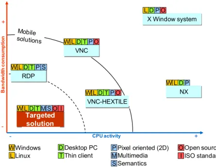
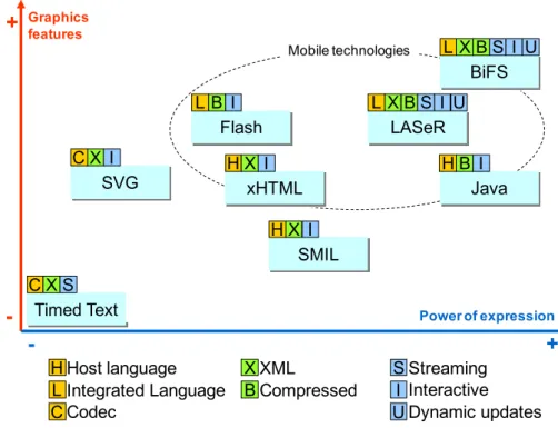
The current solutions can be represented in terms of power of expression and graphic features, see Figure 2.2. This figure was obtained by extending a similar representation in [LASeR, 2006]. The power of expression (on the abscissa) represents the possibility of describing complex/heterogeneous scenes. The graphics features (on the ordinate) relates to the visual quality of the displayed content.
It can be seen that LASeR is a priori the most suitable technology for creating mobile thin applications. BiFS is the second best solution, with more powerful tools for describing complex heterogeneous scenes, with high quality elementary components. These two technologies will be detailed below.
Figure 2.2. Concurrent solutions for heterogeneous content encoding, updating and streaming
2.1.3. BiFS and LASeR principles
Overview
We will investigate the existing multimedia scene technologies and we will discuss the peculiarities of BiFS and LASeR as well as their potential for serving mobile remote display purposes.
The MPEG-4 audio-visual scenes are composed of diversity media objects, structured in a hierarchical order forming a tree. At the ends of the hierarchy, two types of objects can be generally found: multimedia objects and primitive media objects. While analyzing one heterogeneous scene, Figure 2.1, we can notice the following multimedia objects:
images (e.g. uncompressed RAW, or compressed png and/or jpeg, …); video objects (e.g. real-time video stream);
audio objects (e.g. the audio from the video streamed);
followed by the primitive media objects, capable of representing synthetic content: text (e.g. representation of an textual information);
graphics (e.g. lines, rectangles, …).
Such an object partitioning allows the content creators to construct complex scenes and enables the users to interact and manipulate them.
Flash SVG SMIL Timed Text xHTML Java LASeR BiFS H X I H X I C X S C X I L B I L X B H B I S I U L X B S I U
+
-+
-
Power of expression Graphics features H L C X B S I U Host language Integrated Language Codec XML Compressed Streaming Interactive Dynamic updates Mobile technologiesBinary Format for Scenes (BiFS)
MPEG-4 defines a dedicated description language, called Binary Format for Scene (BiFS) [Battista, 1999], [Battista, 2000], which is able to describe the heterogeneous content of the scene, to manage the scene object behavior (e.g. object animation) and to ensure the timed and conditional updates (e.g. user input/interactivity). While BiFS at the content representation level BiFS can be considered as an additional layer over VRML, it also provides supports for optimized content compression and delivery.
A BIFS scene is represented as a hierarchical structured (a tree) of nodes2. Each node contains not only information about the audio-visual object in the scene but also about the spatio-temporal relations among such objects (i.e. the scene description), about the user possibility to interact with that object, etc. Individual nodes can be logically grouped together, by using a devoted node (the grouping node), see Figure 2.3. Note that the scene description can evolve over time by using scene description updates.
The novelty of BiFS does not only relate to the scene description but also to the scene compression. Traditionally, the heterogeneous visual content to be remotely displayed was represented by successive frames composing a single video to be eventually compressed by some known codec (such as MPEG-2 [MPEG-2, 2007] or MPEG-4 AVC [AVC, 2012]). BiFS follows a completely different approach, by allowing each object to be encoded with its own coding scheme (video is coded as video, text as text, and graphics as graphics).
In order to facilitate the user interaction with the audio-visual representation, BiFS supports interaction between the user and the objects. The interactivity mechanisms are integrated within the scene description information referred to as sensors, which are special nodes that can trigger user events based on specific conditions (e.g. keyboard key pressed and/or mouse movements). These sensors can handle two types of interactivity: client-side and server-side. The client-side interactivity deals with content manipulation on the end user terminal, where only local scene updates are available: the user events are captured and the scene description is correspondingly updated, without contacting the server.
2
Figure 2.3. BiFS scene-graph description example
The server-side interactivity supposes that the user events are sent to the server by using an up-link channel. MPEG-4 provides two possible solutions for ensuring the server-side interactivity. First, the ECMA script (JavaScript language) can be considered in order to enable programmatic access to MPEG-4 objects. In order to achieve server-side interactivity, an AJAX HttpRequest [Bruno, 2006] object is used to send user interactivity information to the server. In the particular case of BiFS, a second interactivity mechanism is provided by the ServerCommand [BiFS, 2006] which allows the occurrence of a user event to be directly signaled from the scene to the server. An example of a BiFS scene description, considering the Figure.2.3 represented in a textual VRML format is represented in Code 2.1, follows:
InitialObjectDescriptor { objectDescriptorID 1 audioProfileLevelIndication 255 visualProfileLevelIndication 255 sceneProfileLevelIndication 254 graphicsProfileLevelIndication 254 ODProfileLevelIndication 255 esDescr [ ES_Descriptor { ES_ID 1 decConfigDescr DecoderConfigDescriptor { streamType 3 decSpecificInfo BIFSConfig { isCommandStream true pixelMetric true pixelWidth 800 pixelHeight 600 } } } ] }
orderedgroup DEF Scene-graph OrderedGroup { children [ DEF B Background2D { backColor 1 0 0 } WorldInfo { info [ "Example" ]
title "examplifying the Figure 4.3" }
transofrm DEF Window1 Transform2D { children [
transform DEV Video Transform2D { scale 1 1 children [ Inline { url [OD:8] } ] }
transform DEF SimpleGraphics Transform2D { children [ Shape { appearance Appearance { material Material2D { emissiveColor 0 0 0 filled TRUE } } geometry Rectangle { } } Shape { appearance Appearance { material Material2D { emissiveColor 0 0 0 filled TRUE } } geometry Line { } ... } ] }
transform DEF Text Transform2D { children [
Shape {
appearance DEF TA Appearance { material Material2D { emissiveColor 1 1 1 filled TRUE } } geometry Text { string [ "big_buck_bunny_480p_h264" ] fontStyle DEF FS FontStyle {
size 20 family "SANS" } } } ] } ] }
transofrm DEF Window2 Transform2D { children [
transform DEF Background Transform2D { children [ Shape { appearance Appearance { material Material2D{ emissiveColor 1 0 1 filled TRUE } } geometry Rectangle { radius 50 } }
transform DEF Images Transform2D { translation 80 90 children [ Shape { appearance Appearance { texture PixelTexture { image 4 4 2 0x00FF 0x00FF 0x0000 0x0000 } } geometry Circle { radius 50 } } Shape { appearance Appearance { texture PixelTexture { image 4 4 2 0x00FF 0x00FF 0x0000 0x0000 } } geometry Circle { radius 50 } } ... ] } ] } ] } ] } AT 0 { UPDATE OD [
ObjectDescriptor { objectDescriptorID 8 URLstring "big_buck_bunny.mp4" } ] }
Code 2.1. Example of BiFS scene-graph, represented using VRML
The complete BiFS scene description, corresponding to Figure 2.3 has the following structure: a header that contains some global information about the encoding;
a binary value representing the Transform node;
a bit specifying that the fields of the Transform node will be specified by their index, rather than in an exhaustive list;
the index for the ‘translation’ field;
a binary encoding of the SFVec2f value 0 0 (since there is no quantization defined here, this encoding consists of three 32-bit values; during decoding, the decoder knows the type of the field it is reading and thus knows how many bits to read and how to interpret them);
the index of the children field of the Transform node; the binary representation of the Shape node, which is:
o a binary value for the Shape node;
o a bit specifying that all of the fields of the Shape node and their values will be listed sequentially rather than by index/value pairs;
o a binary representation for the Rectangle node which is: a binary value for the Rectangle node;
a bit specifying that the fields of the Cube will be specified by index; the index of the ‘size’ field;
a binary encoding of the SFVec2f value 1 1;
a bit specifying that no more fields for the Rectangle node will be sent; o a binary value for the Appearance node, followed by its encoding(omitted here); a bit terminating the list of fields for the Transform node.
Lightweight Application Scene Representation (LASeR)
The BiFS principles have been further optimized for thin clients and mobile network purposes, thus resulting in a standard called Lightweight Application Scene Representation (LASeR) [LASeR, 2005], [Dufourd, 2005].
Properly referred to as MPEG-4 Part 20, MPEG-4 LASeR is designed for representing and delivering rich-media services to resource-constrained devices such as mobile phones. A LASeR engine, Figure 2.4, has rich media composition capabilities relying on the usage of an SVG scene tree. After binary encoding of the LASeR scene, the LASeR commands are the main enablers for
dynamic scene updating and real-time streaming. The LASeR binary format is based on a generic Binary MPEG (BiM) [BiM, 2006] format, which applies encoding according to an already known XML schema. This approach makes the BiM format a schema aware encoding, i.e. it is based on the mutual knowledge of the schema between both the server (encoder) and the client (decoder).
As previously stated LASeR is capable of capturing the user events at the scene description level. When considering the high demands of interactive LASeR services, multiple connections from different audio-visual media objects, distributed on different locations, should be supported, hence a new type of service is required. In this respect, the Simple Aggregation Format (SAF) is specified so as to enable the creation of a single LASeR stream in an efficient way, ready to be streamed through the network.
The general overview of the LASeR brings to light that:
it is devoted only to 2D scenes encoding, including vector graphics, and timed modifications of the scene;
SAF (Simple Aggregation Format) alleviates the aggregation of all the streams into a single LASeR stream.
Figure 2.4. LASeR architecture (cf. [LASeR, 2005])
<?xml version="1.0" encoding="UTF-8"?> <saf:SAFSession xmlns:saf="urn:mpeg:mpeg4:SAF:2005" …> <saf:sceneHeader> <LASeRHeader …/> </saf:sceneHeader>
<saf:RemoteStreamHeader streamID="Video0" objectTypeIndication="32" streamType="4" source="[video stream]"/>
<saf:endOfStream ref="Video0"/> <saf:sceneUnit>
<lsru:NewScene>
<svg width="800" height="600" viewBox="0 0 800 600" version="1.1"baseProfile="tiny"> <g lsr:id="Window1" lsr:translation="45 0"> Application … font image video audio SVG Scene Tree LASeR
extensions LASeR commands Binary encoding Transport SAF Network
<video begin="2" xlink:href="#Video0" width="100" height="80" repeatCount="3" transformBehavior="pinned"/>
<rect transform="translate(165, 220)" fill="white" stroke="white"></rect> <line transform="translate(165, 220)" fill="white" stroke="white"></line> <text font-family="SYSTEM" font-size="12" font-style="italic" id="text" y="88" text-anchor="start" display-align="before">
Un text </text> </g>
<g lsr:id="Window2" lsr:translation="45 0">
<rect transform="translate(165, 220)" fill="gray" stroke="red"></rect> <image id="image1JPEG" x="" y="0" width="" height="150"
xlink:href="../icon1.png"/>
<image id="image1JPEG" x="" y="0" width="" height="150" xlink:href="..."/> .... </g> </svg> </lsru:NewScene> </saf:sceneUnit> <saf:endOfSAFS>
Code 2.2. LASeR scene example of the Figure 4.3, including SAF aggregation
2.1.4. Conclusion
MPEG-4 BiFS and LASeRare potentially capable of fulfilling key remote display requirements: the heterogeneous content generated by the application can be aggregated into a
multimedia MPEG-4 scene-graph, and the related semantic information can be used for the management of this graph;
the compression of each type of content (text, audio, image, graphics, video, 3D) by dedicated codecs and the related live streaming are possible by using the corresponding BiFS/LASeR technologies;
the user interactivity can be established both locally and remotely;
the client CPU activity may concern only light-weight operations (scene-graph rendering and basic user event handling) while the computational intensive operations (scene-graph creation/management and user event management) may be performed by the server.
Besides these technical properties, BiFS and LASeR also have the advantage of being stable, open international standards, reinforced by open source reference software supports.
2.2 Mobile Thin Clients technologies
2.2.1. Overview
Nowadays, all the thin clients solutions (be they wired or wireless, desktop computer or thin client oriented, Windows or Unix based, etc.) exploit the client-server architecture. Consequently, any remote display technological support can be assessed according to the following three criteria: (1) the level of interception of the visual content, generated by the application at the server side, (2) the compression methods and the protocol used for transmission of the content to the client, and (3) the management of the user interactivity (including the transmission of the user events from client to server). When targeting mobile thin clients, an additional fourth criterion related to the energy consumption is taken into account. The study in [Carroll, 2010] brought to light that the energy consumption on a smartphone depends on the network (GSM/Wi-Fi), CPU, RAM, display and audio. While the last three factors are rather related to the device and to the user behavior, the amount of data transmitted through the network and the CPU activity intrinsically depend on the technology and will be further investigated in our study.
The present section considers the most often encountered desktop thin clients support technologies (X window, NX, VNC, and RDP) and discusses them according to these criteria.
2.2.2. X window system
The X window system represents native thin client framework for all current day desktops, and it is exploited mostly by Linux applications accommodating an XClient and an XServer connected trough XProtocol. The X window system terminology defines the user terminal, where the applications are displayed as the XServer, and the server running the application as the XClient [Nye, 1990]. Based on its specification and implementation, the client and the server are able to run on the same machine (PC) or distributed, by using several hardware architectures and operating systems (Unix, Linux, …), see Figure 2.5.
The graphical output generated by the application Graphical User Interface (GUI) is traditionally structured in a hierarchical order, defining a top level element, usually a Window, and followed by other windows or elements as children to the root window. The communication protocol (XProtocol) between the server and the client was design to support a basic set of 119 requests, generated by the application output. This protocol ensures all bi-directional communication tasks but makes no provision for content compression. Besides the requests, the XProtocol structure has replies, events, and errors:
request: the client requests information from the server or requests an action (like drawing, menu closing, …);
reply: the server responds to a request (not all requests generate replies);
event: the server sends an event to the client (e.g. keyboard or mouse input, or a window being moved, resized or exposed);
error: the server sends an error packet if a request is invalid.
Although particular applications may require some graphic extensions, the practice shows that a sub-set of 20 graphical requests are sufficient for displaying the large majority of application. As an example, when considering www browsing for 5 minutes, more than 70% of the total number of generated graphic primitives is covered by: CreatePixmap, PutImage, CopyArea, CreateGC, PolyFillRectangle, PolyRectangle, PolySegment, FillPoly, PolyLine, CreateWindow, ConfigureWindow, PolyText8.
The rendering mechanism for the X windows system is illustrated in Figure 2.6.
Figure 2.6. X window system server and client side content rendering
An example of X polySegment, putImage and polyText16, graphical requests, uncompressed description (including the used bites) follows:
Images (uncompressed) Simple graphics (lines, rectangles,...)
Images (24 & 1 bit depth)
Server side content rendering Text / Images (native font) Video (encoded video) Simple graphics (lines, rectangles,…) Images (24 & 1 bit depth)
Text (native font)
Client side content rendering
X polySegment
Bytes type description
1 66 opcode 1 unused 2 3+2n requestlength 4 DRAWABLE drawable 4 GCONTEXT gc 8n LISTofSEGMENT segments
Code 2.3. X Protocol request description, polySegment
X putImage
Bytes type description
1 72 opcode 1 format 0 Bitmap 1 XYPixmap 2 ZPixmap 2 6+(n+p)/4 requestlength 4 DRAWABLE drawable 4 GCONTEXT gc 2 CARD16 width 2 CARD16 height 2 INT16 dst-x 2 INT16 dst-y 1 CARD8 left-pad 1 CARD8 depth 2 unused n LISTofBYTE data p unused, p=pad(n)
Code 2.4. X Protocol request description, putImage
X polyText16
Bytes type description
1 74 opcode 1 unused 2 4+(n+p)/4 requestlength 4 DRAWABLE drawable 4 GCONTEXT gc 2 INT16 x 2 INT16 y n LISTofTEXTITEM8 items
p unused, p=pad(n) (p is always 0 or 1)
Code 2.5. X Protocol request description, polyText16
While ensuring good performances when implemented on a single desktop environment, the X window system cannot be directly employed in distributed environments (where the client and the server installed on separate machines). For instance, the video generated at the server side cannot be displayed as a video per-se at the client side. By default, the video is converted in RAW (uncompressed) sequences of images which are subsequently transmitted and displayed at the client side, see Figure 2.6. The same situation may occur for other type of content, like the
fonts. Consequently, an artificially overcharged traffic is generated between server and client, thus making it impossible for the X window system to be implemented for mobile thin client applications.
On the client side, the XServer only displays the graphical content without making a provision for capturing the user interactivity. The user events are captured at the XClient only by generic Linux/Unix OS mechanisms (keyboard/mouse drivers).
By summarizing the X window system functionalities, we can notice the following peculiarities: XServer
o displaying the graphical requests. XClient
o executes the applications; o captures the user interaction. XProtocol
o each attribute from the specification has a fixed length; o no provision for compression;
o no provision for video streaming in distributed environments.
2.2.3. NoMachine NX technology
By providing an alternative protocol, NoMachine propose an open solution, NX technology, intended to reduce the X Protocol network consumption and latency, while benefiting from the complete X windows system functionality. In this respect, two new modules, the NX Agent and NX Proxy, are designed, see Figure 2.7.
Figure 2.7. NoMachine architecture
The NX Proxy is responsible for applying a compression and decompression to the XProtocol. Hence, its implementation is required at both the XServer and XClient sides and an underlying protocol (the NX protocol) is defined accordingly.
The NX Agent is required only at the client side, in order to avoid the unnecessary XProcotol data round trips.
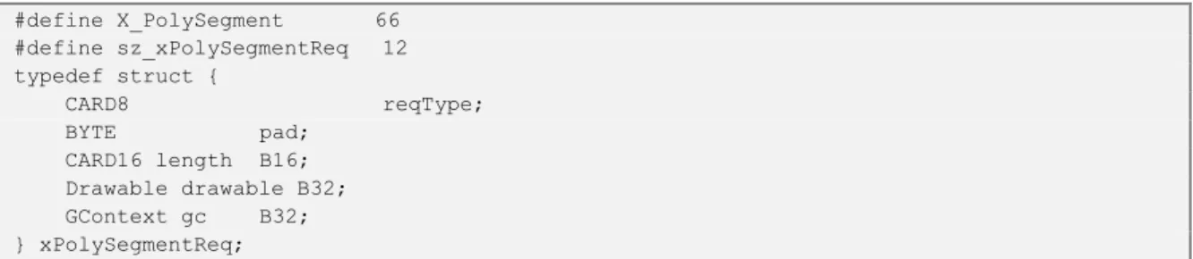
The NX technology considers all XProtocol message to be composed of two parts: a fixed size part called identity, and a dynamic size part called data. This way, the NX compression algorithm can be applied to the data, where the information is dynamically generated and likely to be different on each message. For instance, consider the case of the compression of the polySegment XProtocol request. The data part for the polySegment is a list of 2D coordinates, each of which is represented as signed integers. The NX compression is achieved by representing each coordinate in the list as a relative value with respect to its predecessor. This way, on average, an X polySegment request of 32 bytes can be fully encoded in 32 bits (an average compression ratios ranging of 8:1). This compression mechanism is illustrated below, as the C language representation of the X Protocol polySegment request from Xproto.h library:
#define X_PolySegment 66 #define sz_xPolySegmentReq 12 typedef struct { CARD8 reqType; BYTE pad; CARD16 length B16; Drawable drawable B32; GContext gc B32; } xPolySegmentReq;
Code 2.6. Code sample written in C language for compressing the polySegment X request
However, the basic X windows limitations in video/text representation in distributed environments are still present, see Figure 2.8: this type of content is converted into images which are displayed on the client side. However, the network consumption is alleviated by introducing a special NX Protocol message, NX_PutPackedImage allowing the transmission of compressed images, in the JPEG or PNG formatted [JPEG, 1996], [PNG, 2004], for instance.
Figure 2.8. NX client-server rendering
Images (24 bit depth compressed) Simple graphics (lines, rectangles,...) Images (24 & 1 bit depth) Server side content rendering Text / Images (native font) Video (encoded video) Simple graphics (lines, rectangles,…) Images (24 & 1 bit depth)
Text (native font)
Client side content rendering

![Figure 2.4. LASeR architecture (cf. [LASeR, 2005])](https://thumb-eu.123doks.com/thumbv2/123doknet/2907021.75356/42.892.247.660.599.881/figure-laser-architecture-cf-laser.webp)