HAL Id: hal-02096596
https://hal.archives-ouvertes.fr/hal-02096596
Submitted on 11 Apr 2019
Livrable 3.2 - GNSS Quantitative Analysis for ERSAT
GGC Project - Projet ERSAT GGC - ERTMS on
SATELLITE Galileo Game Changer
Francesco Sperandio, Silvia Sturaro, Salvatore Sabina, Julie Beugin
To cite this version:
Francesco Sperandio, Silvia Sturaro, Salvatore Sabina, Julie Beugin. Livrable 3.2 - GNSS Quantitative Analysis for ERSAT GGC Project - Projet ERSAT GGC - ERTMS on SATELLITE Galileo Game Changer. [Research Report] IFSTTAR - Institut Français des Sciences et Technologies des Transports, de l’Aménagement et des Réseaux. 2018, 46p. �hal-02096596�
`
ERTMS on SATELLITE Galileo Game Changer
Deliverable 3.2
GNSS Quantitative Analysis for ERSAT GGC Project
Due date of deliverable: 30/09/2018
Actual submission date: 29/10/2018
Leader/Responsible of this Deliverable: RINA-C
Reviewed: Y/N
Document status
Revision Date Description
00 14/10/2018 Internal check
01 16/10/2018 For review to project partners
02 29/10/2018 Comments implemented
Project funded from the European Union’s Horizon 2020 research and innovation programme
Dissemination Level
PU Public X
CO Confidential, restricted under conditions set out in Model Grant Agreement
CI Classified, information as referred to in Commission Decision 2001/844/EC
Start date of project: 01/12/2017 Duration: 24 months
This deliverable was prepared as part of the project ERSAT GGC, receiving funding from the European GNSS Agency (GSA) under the European Union's Horizon 2020 research and innovation programme, under grant agreement No 776039. Neither the GSA nor any agency thereof, nor any of their employees, nor any of their contractors, subcontractors or their employees, makes any warranty, express or implied, or assumes any legal liability or responsibility for the accuracy, completeness, or any third party's use or the results of such use of any information, apparatus, product, or process disclosed, or represents that its use would not infringe privately owned rights.
`
REPORT CONTRIBUTORS
Name Company Details of Contribution
SPERANDIO Francesco RINA-C Author
STURARO Silvia RINA-C Author
SABINA Salvatore ASTS Contributor and Reviewer of all document
BEUGIN Julie IFSTTAR Contributor especially for uncertainty analysis
GUERRUCCI Luigi RFI Reviewer
BENUSIGLIO Stefano BVI Reviewer
DOCUMENT APPROVAL
Document Code
Rev. Approved
Authorised
Date
ERSAT-GGC_WP3_D3.2_GNSS Quantitative
`
EXECUTIVE SUMMARY
In order to apply the Enhanced ERTMS/ETCS Functional Architecture, capable of using GNSS and Public Radio TLC Technologies, the safety aspects of the ERTMS/ETCS system upon the future application of the above mentioned positioning and communication technologies have to be investigated.This document describes the Quantitative Safety and Hazard Analysis carried out in ERSAT GGC WP3 - Task 3.2 and reports the relative results.
`
TABLE OF CONTENTS
EXECUTIVE SUMMARY ... 3 TABLE OF CONTENTS ... 4 LIST OF FIGURES ... 5ACRONYMS AND DEFINITIONS ... 6
1. BACKGROUND ... 8
2. OBJECTIVE ... 9
3. INTRODUCTION ... 10
4. THE ANALYSIS FOCUS ... 11
5. REFERENCES AND GENERALITIES FOR THE QUANTITATIVE SAFETY ANALYSIS ... 13
6. FAULT TREE ANALYSIS METHODOLOGY ... 14
7. THE PRELIMINARY FAULT TREE ANALYSIS ... 15
7.1THEPRELIMINARYETCSCOREHAZARDAPPORTIONMENT ... 15
7.1.1 THE THR-ONBOARDAPPORTIONMENT ... 17
7.1.2 THE THR-TRACKSIDEAPPORTIONMENT ... 20
7.1.3 THE THR-RTXAPPORTIONMENT ... 21
8. THE INFORMATION POINT HAZARDS ... 24
9. PROTECTION AGAINST TRANS-VBALISE-2 AND 3 ... 27
9.1TRANS-VBALISE-2 ... 27
9.2TRANS-VBALISE-3 ... 28
10. OPERATIONAL CONSIDERATIONS FOR TRANS-VBALISE-2 AND -3 ... 29
10.1TRANS-VBALISE-2 ... 30
10.2TRANS-VBALISE-3 ... 30
11. THE FINAL APPORTIONMENT ... 30
11.1SOM WITH Q_STATUS=“KNOWN” ... 31
11.2SOM WITH Q_STATUS=“UNKNOWN” AT TERMINAL /INTERMEDIATE RAILWAY STATION ... 31
11.3SOM WITH Q_STATUS=“UNKNOWN” IN LINE ... 32
11.3.1 THR-VBTX-SRAPPORTIONMENT ... 33
11.3.2 H7-SRAPPORTIONMENT ... 35
11.3.3 H9-SRAPPORTIONMENT ... 37
`
LIST OF FIGURES
Figure 1 – Preliminary ETCS Core Hazard apportionment - On-board and Trackside ... 16
Figure 2 – The THR-ONBOARD apportionment. ... 18
Figure 3 – The THR-TRACKSIDE Apportionment ... 20
Figure 4 – The THR-RTX Apportionment ... 22
Figure 5 – Preliminary ETCS Core Hazard apportionment to Balise Transmission System ... 26
Figure 6 – The THR-VBTX-LINE-SR apportionment down to TRANS-VBALISE-1, 2, 3 ... 33
Figure 7 - The H7-SR apportionment ... 35
Figure 8 - The H9-SR apportionment ... 37
`
ACRONYMS AND DEFINITIONS
Acronym Description
AL Alert Limit
APV Approach with Vertical Guidance
ATPE Along Track Position Error
ATPL Along Track Protection Level
BG Balise Group
BTM Balise Transmission Module
DB Database
ERSAT-GGC ERTMS on SATellite – Galileo Game Changer
ERTMS European Rail Traffic Management System
ETCS European Train Control System
ETS Eurobalise Transmission System
FDE Fault Detection and Exclusion
FMECA Failure Mode, Effects, and Criticality Analysis
GAD/TV GNSS Augmentation Dissemination/ Trackside Verification
GIVE Grid Ionospheric Vertical Error
GNSS Global Navigation Satellite System
HW Hardware
LOS Line of Sight
MA Movement Authority
MDE Minimum Detectable Error
MI Misleading Information
MLCP Multi-Link Communication Platform
MTCP Multipath TCP
NLOS Non Line of Sight
PBG Physical Balise Group
PL Protection Level
PR Pseudo-range
PVT Position, Velocity, Time
QoS Quality of Service
RAIM Receiver Autonomous Integrity Monitoring
RBC Radio Block Center
SIL Safety Integrity Level
`
Acronym Description
TTA Time To Alarm or Time to Alert
UDRE User Differential Range Error
VB Virtual Balise
VBD Virtual Balise Detection
VBG Virtual Balise Group
VBR Virtual Balise Reader
VBTS Virtual Balise Transmission System
WP Work Package
Table 1 – Acronyms
Term Description
Q_STATUS Status of SoM position report (UNISIG SUBSET-026 [R3])
Information Point
Specific location on the track where information can be transmitted from ERTMS/ETCS trackside to ERTMS/ETCS on-board equipment (UNISIG SUBSET-023 [R4])
VBTS-related messages
The messages exchanged between on-board and trackside VBTS functional blocks concerning e.g. Command & Control and/or Augmentation & Integrity (see D 2.1 [R1])
`
1. BACKGROUND
ERSAT GGC (Grant Agreement No 776039) is a project of the RFI ERSAT program launched in 2012 for integrating satellite technology on ERTMS platform. The primary goals of ERSAT GGC is to launch an operational line by 2020 and accelerate the standardization process at European level for including the satellite technology in the new ERTMS Standard for Technical Interoperability (STI).In the framework of the Project ERSAT GGC, the WP3 is related to Safety and Hazard Analysis of the Enhanced ERTMS Functional Architecture, defined through the WP2 activities and previous related research projects, for the introduction of the GNSS technology, and consequently derived Virtual Balise concept, and Public Radio TLC Communication Network.
It is noteworthy that the Enhanced ERTMS Functional Architecture has been defined aiming at reaching:
A minimum impact on current specifications; A functional retrofit UNISIG Compliant;
The achievement of the SIL 4 safety integrity level. The WP3 activities are split into two main tasks:
Task 3.1, addressed in Deliverable: ERSAT_GGC_WP3_D3.1, “Safety Analysis of ERSAT ERTMS Application over GNSS” Rev 0.2, which identifies and qualitatively assesses the hazardous failures potentially arisen after the integration of the Virtual Balise concept and Public Radio TLC related functional blocks within the current ERTMS architecture;
Task 3.2, aims at addressing the quantitative aspects of the safety analysis and deriving the Tolerable Hazard Rates to be fulfilled to ensure a safe use of the architecture, the compliance with reference regulations and the technical interoperability.
The present report, referred as deliverable D3.2, is the output of the Task 3.2.
The Quantitative analysis developed herein aims at defining the targets enabling the technical interoperability for the safety-related functions of the ERSAT-GGC Enhanced ERTMS Architecture, which integrates the GNSS based Virtual Balise Concept.
`
2. OBJECTIVE
The aim of this document is to complete the set of Safety and Hazard Analysis for ERSAT-GGC Enhanced ERTMS architecture providing a reference Fault Tree and related numerical targets for the rates of the technical failures, due to the novel function integration, affecting ETCS safety. The resulting Tolerable Hazard Rates should support future suppliers in the Interoperability verification.
In line with previous NGTC D7.7 [R11] analysis, this work has been carried out according with SUBSET-091 [R7] and SUBSET-088 Part 3 [R6] apportionment approach.
`
3. INTRODUCTION
The Quantitative analysis object of this Deliverable is structured as detailed below.Section §1 provides the ERSAT GGC project background and the WP3 role description. Section §2 presents the objective of the present analysis.
Section §3, the present Section, provides the document structure overview. Section §4 outlines the GNSS Quantitative Analysis focus.
Section §5 reports the analysis references and derived approach. Section §6 presents the Fault Tree Analysis (FTA) Methodology.
Section §7 presents the Preliminary Fault Tree Analysis, focused on the ETCS Core Hazard apportionment, including VBTS integration.
Section §8 presents the Hazards applicable to the generic Balise Transmission System.
Section §9 presents the protection means against the Virtual Balise Transmission System Hazards. Section § 10 provides some consideration on the Virtual Balise Transmission System Hazards based on the Operational conditions.
Section § 11 reviews the Preliminary ETCS Core Hazard apportionment of § 7 down to the Balise Transmission Subsystem upon the specific Operational Scenario.
Section § 12 presents the top-down Virtual Balise Transmission System Hazard rate apportionment, amending the preliminary allocation on the basis of § 8, § 9 and § 10 outcomes, and the final considerations upon the performed THR apportionment for the Enhanced ERTMS Functional Architecture interoperability.
`
4. THE ANALYSIS FOCUS
In line with the qualitative study performed in D3.1 [R2], the Safety and Hazard analysis scope focuses on the integration of the Virtual Balise Transmission System and GNSS interface. The Public TLC Networks are out of the Safety scope of Work, see D3.1 [R2].With reference to ERSAT-GGC Enhanced ERTMS Functional Architecture defined in [R1], the VBTS has been classified as:
Trusted (safe) parts:
o Virtual Balise Reader safety related Functions,
o GNSS Augmentation Dissemination / Trackside Verification Functions; Non trusted parts:
o Global Navigation Satellite total System, the combined ground and airborne subsystems, referring to its role as a source of positioning errors (i.e. feared events originating from satellite failures, such as ephemeris errors,
o pseudorange / clock errors; and feared events related to failures within the augmentation system);
o GNSS Signal in Space, referring to its role as a source of positioning errors (i.e. feared events originating from the propagation environment including);
o On-board GNSS antenna.
The VBTS integration within the ERTMS/ETCS have as primary object the large application of ETCS (that can be enabled by less expensive implementation) to Conventional railway lines without decreasing the current ETCS safety level.
The minimum impact on the existing UNISIG approved Reference Architecture has been the key-points that guided the definition of the ERSAT-GGC Enhanced ERTMS Functional Architecture (see [R1]).
In order not to change or to minimize the modification on the current specification and the ERTMS system architecture, the technical interoperability between the current physical balise technology and the virtual balise one (that would be functionally equivalent to the current one) shall be ensured in the applicable ERTMS operational scenarios.
Specifically, the interoperability is required for both the on-board and the trackside functional blocks and interfaces (GNSS air gap included) enabling the Virtual Balise detection, which ensure the integrity of the retrieved train position.
This analysis moving from the already performed Functional FMECA (please refer to [R2]), aims at:
Modelling the combination of the current ETCS functions with the VBTS ones, and related technical failures that can threat the ETCS safety. The VBTS interfaces with ETCS and the airgap with GNSS are especially explored;
`
Identifying the safety targets (the Tolerable Hazard Rates (THR)) for the VBTS related hazards by apportioning the ETCS global safety target (refer to analysis methodology described in § 5);
If necessary, amending the THR against the specific operational scenarios (those defined in ERSAT-GGC Deliverable D2.1 [R1]);
Synthetizing in a conclusion the numerical targets to be fulfilled to ensure the safety and interoperability of the Enhanced ERTMS/ETCS functions.
Note: Since the Virtual Balise information is stored on-board before its use , the VB concept is not applicable to ETCS Level 1 based on switchable Eurobalises, but instead addresses at least in ETCS Level 2.
Thus, the analysis itself and the related outcomes would support the future suppliers in the safety and interoperability verification of the Enhanced ETCS at least Level 2 applications.
`
5. REFERENCES AND GENERALITIES FOR THE QUANTITATIVE
SAFETY ANALYSIS
The starting point of this GNSS quantitative analysis for ERSAT-GGC Enhanced ERTMS Architecture is the analysis and related results developed in Deliverable 7.7- Annex F [R11] of the NGTC project. The ERSAT-GGC functional architecture has confirmed or revised some ETCS enhanced functionalities (e.g. the use of the Track Database information) reaching a higher stability with respect to NGTC Project.Therefore, the quantitative safety analysis carried out herein takes as starting reference the NGTC targets and confirm or amend them based on the following inputs:
ERSAT-GGC D2.1 [R1], which describes the Enhanced ERTMS Functional architecture and the ERSAT-GG considered ERTMS Operational Scenarios;
ERSAT-GGC D3.1 Functional FMECA [R2], which provide awareness about the hazardous technical failure modes that can arise due to the integration of GNSS information and related enhanced functionalities that can affect the ETCS safety.
In line with NGTC D7.7 Annex F analysis [R11], the present document develops a Fault Tree Analysis (FTA) based on SUBSET-091 [R7] apportionment, which apportions the approved Tolerable Hazard Rate for technical failures of ETCS equally between On-board and Trackside parts.
Furthermore, as per the project purpose aiming at the minimum impact on the existing ERTMS/ETCS Level 2 reference architecture, the analysis keeps as reference the SUBSET-091 [R7] for the high-level quantitative safety requirements given as minimum targets to ensure that ETCS may be safely integrated in any interoperable railway system.
As far as the mission profile is concerned, the analysis keeps the same figures as the ones of the UNISIG Subset-091 [R7].
Standing the scope of the ERSAT GGC project, the assumptions for the standard mission profile can be considered applicable with a conservative level of confidence. Anyhow, it shall be observed that the technical solution might bring to reduce the number of installed balise groups along the trackside with respect of the assumptions made by UNISIG Subset-091 mission profile [R7]. Then each on board supplier shall verify that this condition does not impact negatively the BTM safety performances considering the specific trackside project [ERSAT_GGC_D3.2_07].
`
6. FAULT TREE ANALYSIS METHODOLOGY
The analysis has been developed following the top down apportionment of the existing UNISIG THR for ETCS reference architecture of SUBSET-091 [R7] and SUBSET-088 Part 3 [R6].The FTA is based on the ETCS Core Hazard THR apportionment for to the hazard rates of the UNISIG grouping of constituents undertaken in Subset-088 Part 3, and introduces the VBTS functions within the grouping of constituents (i.e. On-board, Trackside and Transmission Subsystem).
Concerning the VBTS, it is referred as safety-related transmission system (as per EN 50159 [R10]), functionally consistent with the existing Eurobalise Transmission System (ETS).
Keeping the SUBSET-088 Part 3 analysis structure, first a preliminary target allocation for equipment and specific functions is performed, afterward the allocation is amended in order to consider the operational aspects, the protective features inherent in the design of ETCS and the frequency of occurrence of operational events in Conventional Rail.
Specifically:
Section §7 develops an initial THR apportionment down to the three grouping of constituents of the ERTMS reference architecture: i.e. ETCS on-board, trackside and transmission systems. The Balise Transmission System analysis herein is left undeveloped and explored later against specific conditions. This preliminary apportionment reviews the one of SUBSET-088 Part 3 in order to include VBTS related hazards;
Section §8 presents and preliminary analyse the Balise Transmission Systems hazards; Section §9, focusing on VBTS, presents the protection means Virtual Balise Group Deletion
and Insertion Hazards; and accordingly amends the preliminary allocated targets;
Section §10 analyses Virtual Balise Group Deletion and Insertion Hazards in specific Operational Scenarios;
Section §11 develops the VBTS THR apportionment down to its related Hazards, revising the preliminary allocation on the basis of the related protections (presented in §9 ) and critical operational scenarios (presented in §10).
`
7. THE PRELIMINARY FAULT TREE ANALYSIS
This Section develops an initial ETCS THR apportionment process for the Enhanced ERTMS/ETCS Functional Architecture (described in ERSAT-GGC D2.1 [R1]), according to the methodology described in §6.According to SUBSET-088 Part 3 [R6], the apportionment is taken to a point define the maximum tolerable hazard rates required to ensure technical interoperability whilst leaving freedom for an implementation that best suits a suppliers expertise and technology base.
7.1 THE PRELIMINARY ETCS CORE HAZARD
APPORTIONMENT
This part of the document is preliminary apportioning the approved Tolerable Hazard Rate for technical failures of ETCS to Onboard and Trackside equipment, including the relative VBTS functions, for interoperability purpose.
Although the VBTS integration, the ETCS system shall maintain its role as defined in Subset-91 [R7]:
“To provide the driver with information to enable him to drive his train safely and to enforce respect of this information to the extent advised to ETCS.“
The associated hazard is the referred ETCS Core Hazard:
“Exceedance of safe speed or distance limits as advised to ETCS”
According to SUBSET-091 [R7], the maximum allowed rate of occurrence of the ETCS Core Hazard is 2.0*10-9/ hour; i.e. 1.0*10-9/ hour for ETCS on-board installed on a train and 1.0*10-9/
hour for ETCS trackside installed in an area visited by a train during a reference mission.
SUBSET-091 [R7] allocates the hazardous events as either ‘on-board events’, ‘trackside events’
or ‘transmission events’. Based on a uniform apportionment of 2.0*10-9/ hour, 0.67*10-9/ hour is
allocated to each grouping of constituents. Nevertheless the functions corresponding to the ‘transmission events’ are allocated to the on-board or trackside equipment, in order to respect the equal values of THR for on-board and track-side ETCS equipment (see SUBSET-091 [R7]). The quantitative safety requirements for pure on-board and trackside functions are referred as
THR-ONBOARD and THR-TRACKSIDE, respectively. These targets are maintained as per
SUBSET-091 [R7], but the list of respective subordinate events is revised to address the ETCS Level 2 equipment and VBTS functions hazards, as described in § 7.1.1 and § 7.1.2.
Analogously, the hazard apportionment for the Transmission Systems (i.e. THR-TX) is maintained, but the relative subordinate events list is re-elaborated to include the VBTS functions.
`
Furthermore, the THR-TX figure is further explored and elaborated in next sections.
Note: herein THR-BTX is not referring only the Eurobalise Transmission System, but VBTS as well. The ETCS Core THR is apportioned down to the constituent groupings against a definition of the role of that constituent and its related safety hazard, on the basis of system hazardous events identified in SUBSET-088 [R6], where applicable, and the new ones derived in ERSAT-GGC D3.1 FMECA analysis [R2].
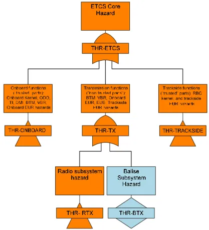
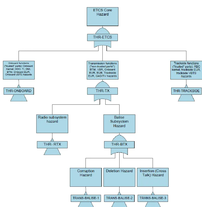
Figure 1 reports the preliminary apportionment of the ETCS THR down to on-board, trackside and transmission subsystem hazards, including VBTS.
For the sake of traceability, the modifications with respect to SUBSET-088 Part 3 are traced in different colours:
All the gates and events modified with respect SUBSET-088 Part 3 in either description or apportionment after VBTS integration are traced in orange colour;
All the new gates and events as introduced herein are traced in grey colour. Further details are provided in Table 3.
`
FT Gate / Event Description Apportioned THR Remarks
THR-ETCS The ETCS Core Hazard 2E-9/h As per Subset-091 [R7]
THR-ONBOARD
The ETCS Onboard Subsystem “Trusted” part (e.g. Odo, Kernel, On-board EUR, BTM, VBR) hazards
0.67E-9/h
THR as per Subset-091 [R7]
Refer to § 7.1.1 for the relative top-down apportionment.
THR-TRACKSIDE
The ETCS Trackside Subsystem “Trusted” part (e.g. RBC Kernel, Trackside EUR, Trackside VBTS) hazards
0.67E-9/h
THR as per Subset-091 [R7]
Refer to § 7.1.2 for the relative top-down apportionment.
THR-TX
The ETCS Transmission Subsystem - “Non Trusted” part (e.g. BTM, VBR, On-board EUR, EUB, Trackside EUR, GAD/TV) hazards
0.67E-9/h THR as per Subset-091 [R7]
THR-RTX Radio subsystem hazards 1E-11/h
THR as per Subset-088- Part 3 [R6], negligible with respect to THR-BTX. Refer to § 7.1.3 for the relative top-down apportionment. THR-BTX Balise Transmission Subsystem
hazards 0.67E-9/h
Preliminary THR as per Subset-088- Part 3 [R6].
Table 3 – The detail of preliminary ETCS Core hazard THR apportionment
The targets provided here above have to be referred as preliminary since no operational assumptions have been done.
Regardless the use of Physical or Virtual Balises, the Balise Transmission system and its associated hazards are analysed in dedicated Chapters (see §8, §9, §10 and §11). This separate analysis is necessary because of the complexity of the analysis resulting from the many uses of the balise sub-system within ETCS.
In the following the further apportionment of THR-ONBOARD, THR-TRACKSIDE and THR-RTX are provided.
7.1.1 The THR-ONBOARD Apportionment
This section details the apportionment of the THR-ONBOARD gate among the subordinate events relative to the purely on-board, trusted functions. According to SUBSET-091 [R7], the ETCS On-board (i.e. excluding the non-trusted transmission functions) must not contribute to the ETCS Core Hazard with a failure rate greater than 1/3 * THR-ETCS.
Therefore, THR-ONBOARD = 0.67 * 10-9 dangerous failures/ hour
`
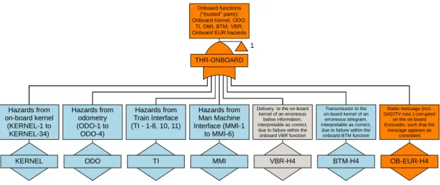
Figure 2 – The THR-ONBOARD apportionment.
Each supplier shall prove the attainment of the THR-ONBOARD, considering, in its specific analysis (e.g., fault tree) for the equipment, at least the following hazardous events (on the basis of SUBSET-088 Part 3 § 7.1.1.2): KERNEL - 1-34 ODO - 1-4 TI - 1-8, 10, 11 MMI–1 - MMI-6 BTM-H4; OB-EUR-H4.
Furthermore, due to the VBTS introduction, the following new hazardous event parallel to BTM-H4 shall be accounted:
VBR-H4: Delivery to the on-board kernel of an erroneous Balise Information, interpretable as correct, due to failure within the on-board VBR function.
Note: with respect to SUBSET-088 Part 3:
LTM-H4 event has not been considered since not relevant for the ERTMS Level 2 applications that use Virtual Balises;
OB-EUR-H4 event description has been modified to account also VBTS-related messages. The apportionment is summed up in Table 4. As per SUBSET-088 Part 3, the THR allocation of the subordinate events is to be undertaken by the supplier.
THR-ONBOARD
1
Onboard functions ("trusted" parts): Onboard Kernel, ODO,
TI, DMI, BTM, VBR, Onboard EUR hazards
KERNEL Hazards from on-board kernel (KERNEL-1 to KERNEL-34) ODO Hazards from odometry (ODO-1 to ODO-4) TI Hazards from Train Interface (TI - 1-8, 10, 11) MMI Hazards from Man Machine Interface (MMI-1 to MMI-6) VBR-H4
Delivery to the on-board kernel of an erroneous
balise information, interpretable as correct, due to failure within the onboard VBR function BTM-H4 Transmission to the on-board kernel of an erroneous telegram, interpretable as correct, due to failure within the onboard BTM function
OB-EUR-H4
Radio message (incl. GAD/TV mes.) corrupted
on the on-board Euroradio, such that the
message appears as consistent
`
FT Gate / Event Description Apportioned THR Remarks
THR-ONBOARD
The ETCS On-board Subsystem “Trusted” part (e.g. Odo, Kernel, On-board EUR, BTM, VBR) hazards
0.67E-9/h THR as per Subset-091 [R7]
KERNEL Hazards from On-board Kernel function -
Events KERNEL - 1-34 accounted, as per Subset-088 Part 3 [R6]
ODO Hazards from Odometry function -
Events ODO - 1-4 accounted as per Subset-088 Part 3 [R6]
TI Hazards from Train Interface -
Events TI - 1-8, 10, 11 accounted as per Subset-088 Part 3 [R6]
MMI Hazards from Man Machine Interface -
Events MMI–1 – MMI-6 accounted as per Subset-088- Part 3 [R6]
VBR-H4
Delivery to the on-board kernel of erroneous balise information, interpretable as correct, due to failure within the onboard VBR function
-
New hazardous event related to the on-board VBTS “Trusted” parts. See Note 1 below.
BTM-H4
Transmission to the on-board kernel of an erroneous telegram, interpretable as correct, due to failure within the onboard BTM function
- Event as per Subset-088
Part 3 [R6]
OB-EUR-H4 Radio message (incl. GADTV mes.) corrupted in onboard Euroradio, such that the message appears as consistent
-
Event based on Subset-088- Part 3 [R6], but re-defined to account also GAD/TV messages corruption.
Table 4 - The detail THR-ONBOARD apportionment
Note 1:
According to [R1], the on-board is assumed as a unique safe platform equipped with both VBR and BTM functions (in the EVC perspective VBR is functionally equivalent to BTM), which are mutually exclusive or the BTM functions prevail on the VBR functions.
During the train run:
the BTM generates the tele powering signal to energize any Eurobalise that it can encounter and receive/decode the telegrams sent by the correct passed physical balises;
the VBR periodically computes the estimated GNSS-based position of the GNSS Antenna installed on the train roof and projected to the track (Virtual Antenna reference mark), and compares it with the locations associated with the virtual balises stored in the on-board track database.
As a principle of correct design of the signalling system the overlapping between the VBR and BTM should be avoided except in specific locations due to safety purposes which assigns priority to the BTM information.
Considering this mutual exclusion between VBR and BTM functions and the highest priority assigned to the BTM functions w.r.t. VBR ones, the higher gate THR-ONBOARD is not modified. In other words, should a PBG detection coincide with the VBG detection, the PBG is dominant.
`
7.1.2 The THR-TRACKSIDE Apportionment
This section details the apportionment of the THR-TRACKSIDE gate among the subordinate events relative to the purely trackside, trusted functions. According to SUBSET-091 [R7], the ETCS Trackside (i.e. excluding the non-trusted transmission functions) must not contribute to the ETCS Core Hazard with a failure rate greater than 1/3 * THR-ETCS.
Therefore, THR-TRACKSIDE= 0.67 * 10-9 dangerous failures/ hour.
Based on SUBSET-088 Part 3 § 8.1.1.4, each supplier shall prove the attainment of the THR-TRACKSIDE considering, in its specific analysis (e.g., fault tree), the following events:
RBC-2, RBC-3 and RBC-4;
Note: Since the RBC handover is out of scope for ERSAT-GGC project, thus RBC-3 and RBC-4 are unchanged.
TR-EUR-H4 for the parts of the hazard that arise due to failures inside the trusted part of the trackside transmission channel. The event description has been modified to include potential failure effects on GAD/TV messages as well.
Note that the introduction of the GAD/TV messages, since a minor percentage of the radio messages, does not change the THR-TRACKSIDE target with respect to SUBSET-091. The THR-TRACKSIDE apportionment considered herein is shown in Figure 3 and described in Table 5. As per SUBSET-088 Part 3, the THR allocation of the subordinate events is to be undertaken by the supplier.
THR-TRACKSIDE
1
Trackside functions ("trusted" parts): RBC kernel, and trackside
EUR hazards
Incorrect RBC radio message sent from the
RBC kernel functions, The RBC misinterprets a message from an adjacent RBC, causing The RBC gives an erroneous
Radio message (incl. GAD/TV mes.) corrupted in
the trackside Euroradio, such that message
`
FT Gate / Event Description Apportioned THR Remarks
THR-TRACKSIDE
Trackside functions ("trusted" parts): RBC kernel, trackside EUR, trackside VBTS hazards
0.67E-9/h THR as per Subset-091 [R7].
RBC-2 Incorrect RBC radio message sent from the RBC kernel functions, such that message appears consistent
- As per Subset-088- Part 3 [R6]
RBC-3
Incorrect adjacent RBC message sent or received by RBC kernel functions as correct, causing an incorrect message to be sent to ETCS kernel
- As per Subset-088- Part 3 [R6]
RBC-4 The RBC gives an erroneous message to
an adjacent RBC -
As per Subset-088- Part 3 [R6]
TR-EUR-H4
Radio message (incl. GAD/TV mes.) corrupted in the trackside Euroradio, such that the message appears as consistent.
-
Subset-088- Part 3 [R6] event modified to also include failure effects on GAD/TV messages
Table 5 - The detail THR-TRACKSIDE apportionment
7.1.3 The THR-RTX Apportionment
This section details the apportionment of the THR-RTX gate among the subordinate events relative to non-trusted parts of the communication channel in both the on-board and trackside sub systems, after VBTS integration.
In Subset 088 Part 3, the THR-RTX contribution to ETCS Core Hazard is considered negligible (i.e. with respect to Balise Transmission System) since the signalling rules mitigating the radio messages Deletion and the protection mechanisms against their Corruption.
Provided the combination of the existing signalling rules with the relevant D3.1 [R2] safety requirements, the VBTS-related radio messages are assumed to be analogously protected against Deletion and Corruption.
Specifically, REQ. 001, REQ. 002, REQ. 017 (please refer to [R2] for major detail) aim at mitigating the VBTS radio messages Deletion, while the VBTS message Corruption is avoided and controlled with REQ. 012, REQ. 015 and REQ. 016 (please refer to [R2] for major detail).
Therefore the safety target THR-RTX = 1.0 * 10-11 dangerous failures per hour is maintained.
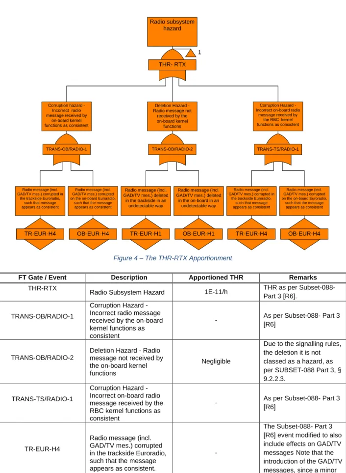
The THR-RTX apportionment considered herein is shown in Figure 4 and described in Table 6. As per SUBSET-088 Part 3, the THR allocation of the subordinate events is to be undertaken by the supplier.
`
Figure 4 – The THR-RTX Apportionment
FT Gate / Event Description Apportioned THR Remarks
THR-RTX
Radio Subsystem Hazard 1E-11/h THR as per Subset-088-
Part 3 [R6].
TRANS-OB/RADIO-1
Corruption Hazard -Incorrect radio message received by the on-board kernel functions as consistent
- As per Subset-088- Part 3
[R6]
TRANS-OB/RADIO-2
Deletion Hazard - Radio message not received by the on-board kernel functions
Negligible
Due to the signalling rules, the deletion it is not classed as a hazard, as per SUBSET-088 Part 3, § 9.2.2.3.
TRANS-TS/RADIO-1
Corruption Hazard -
Incorrect on-board radio As per Subset-088- Part 3
THR- RTX 1 Radio subsystem hazard TRANS-OB/RADIO-1 Corruption hazard -Incorrect radio message received by on-board kernel functions as consistent TRANS-OB/RADIO-2 Deletion Hazard -Radio message not
received by the on-board kernel
functions
TRANS-TS/RADIO-1
Corruption Hazard -Incorrect on-board radio
message received by the RBC kernel functions as consistent
TR-EUR-H4 Radio message (incl. GAD/TV mes.) corrupted in
the trackside Euroradio, such that message appears as consistent
OB-EUR-H4 Radio message (incl. GAD/TV mes.) corrupted on the on-board Euroradio,
such that the message appears as consistent
TR-EUR-H4 Radio message (incl. GAD/TV mes.) corrupted in
the trackside Euroradio, such that message appears as consistent
OB-EUR-H4 Radio message (incl. GAD/TV mes.) corrupted on the on-board Euroradio,
such that the message appears as consistent
TR-EUR-H1 Radio message (incl. GAD/TV mes.) deleted
in the trackside in an undetectable way
OB-EUR-H1 Radio message (incl. GAD/TV mes.) deleted
in the on-board in an undetectable way
`
FT Gate / Event Description Apportioned THR Remarks
messages, does not change THR-RTX target with respect to SUBSET-088.
OB-EUR-H4
Radio message (incl. GADTV mes.) corrupted in onboard Euroradio, such that the message appears as consistent
-
The Subset-088- Part 3 [R6] event modified to also include effects on GAD/TV messages. Note that the introduction of the GAD/TV messages, since a minor percentage of the radio messages, does not change THR-RTX target with respect to SUBSET-088.
TR-EUR-H1
Radio message (incl. GAD/TV mes.) deleted in the trackside in an undetectable way
-
The Subset-088- Part 3 [R6] event modified to also include effects on GAD/TV messages. Note that the introduction of the GAD/TV messages, since a minor percentage of the radio messages, does not change THR-RTX target with respect to SUBSET-088.
OB-EUR-H1
Radio message (incl. GAD/TV mes.) deleted in the on-board in an undetectable way
-
The Subset-088- Part 3 [R6] event modified to also include effects on GAD/TV messages. Note that the introduction of the GAD/TV messages, since a minor percentage of the radio messages, does not change THR-RTX target with respect to SUBSET-088.
`
8. THE INFORMATION POINT HAZARDS
This Section focuses on the generic Balise Transmission Systems hazards.Note, herein THR-BTX is referred as the maximum rate allocated to the generic Balise Transmission System. In the following Sections, depending on the specific scenario, THR-BTX is specified in THR-EBTX or THR-VBTX, in order to distinguish the ETS and VBTS responsibility. Note: Since the use of VBR or BTM is assumed mutually excluding, the same mutual exclusion is holding for THR-EBTX or THR-VBTX.
The functional analysis of SUBSET-088 Part 2 [R6] has identified and associated to ETS the following hazards:
TRANS-BALISE-1: Incorrect balise group message that is received by the on-board kernel functions as consistent (the Corruption Hazard);
TRANS-BALISE-2: Balise group not detected by the on-board kernel functions (the Deletion Hazard);
TRANS-BALISE-3: Inserted balise group message received by the on-board kernel functions as consistent (the Insertion or Cross Talk Hazard).
Concerning VBTS, the Functional FMECA analysis developed in ERSAT-GGC D3.1 [R2] against the ETCS Enhanced architecture, identified the following failures modes affecting the Virtual Balise information:
FI-K 1.4.1.2: The Virtual Balise information is corrupted - The EVC receives a formally Valid VBR information, but it carries an undue (wrong) information content;
FI-K 1.4.1.1: The Virtual Balise information is lost - The EVC does not receive the information (user bits, time stamp, detection error) upon the last VB (e.g. VBG_A);
FB-K 1.4.4: The VBR output information is other than the expected - Although the block has detected the crossing VB (e.g. VBG_A), it outputs the information relative to an undue (i.e. wrong) VB.
These three hazardous events lead to hazards analogous to TRANS-BALISE-1, TRANS-BALISE -2 and TRANS-BALISE -3.
Therefore, this analysis considers the three abovementioned Hazard as applicable to VBTS as well and these are specifically referred as:
`
Concerning TRANS-VBALISE-1, since the Virtual Balise information is received from a SIL 4 platform (i.e RBC) via the safe and secure Euroradio protocol stack and it is stored in the Track DB, the referred Hazard can occur only after a Track DB corruption (please, refer to § 11.3.1 for major detail). This event shall be demonstrated to be negligible, since the safe storage and robust transmission.
Therefore (analogously to ETS analysis in SUBSET-088 Part 3) the initial 1/3*THR-VBTX apportionment shall be amended. Specifically, TRANS-VBALISE-1 is considered negligible with
respect to TRANS-VBALISE-2 and 3. The 50% of THR-VBTX, equal to 0.33*10-9 dangerous failures
per hour, is now allocated to TRANS-VBALISE-2 and 3.
Provided the same apportionment of THR-EBTX and THR-VBTX among the Corruption, Deletion and Cross-Talk Hazards, Figure 5 and Table 7 should be read as applicable to the generic Balise System Hazard. E.g. TRANS-BALISE-1 should be referred as the Corruption Hazard affecting the generic BG, then depending on the specific scenario, TRANS-BALISE-1 may be specified in TRANS-EBALISE-1 or TRANS-VBALISE-1, in order to distinguish the ETS and VBTS responsibility.
`
`
FT Gate / Event Description Apportioned THR Remarks
THR-BTX Balise Transmission Subsystem
hazards 0.67E-9/h
Preliminary THR as per Subset-088- Part 3 [R6], but also applicable to THR-VBTX
TRANS-BALISE-1 Balise Corruption Hazard 1E-11/h
Negligible with respect to TRANS-BALISE-2, 3, as per Subset-088- Part 3 [R6]. Also applicable to TRANS-VBALISE-1
TRANS-BALISE-2 Balise Deletion Hazard 0.33E-9/h
50% of THR-BTX, as per Subset-088- Part 3 [R6]. Also applicable to TRANS-VBALISE-2
TRANS-BALISE-3 Balise Insertion Hazard 0.33E-9/h
50% of THR-BTX, as per Subset-088- Part 3 [R6]. Also applicable to TRANS-VBALISE-3
Table 7 - The detail THR ETCS apportionment down to the generic Balise Transmission System hazards.
Please, note that the same preliminary apportionment for Virtual Balise hazards was provided in NGTC project [R11].
9. PROTECTION AGAINST TRANS-VBALISE-2 AND 3
This Section presents the ETCS inherent protection and/or ERSAT-GGC adopted mitigation rules to avoid the migration of TRANS-VBALISE-2 and -3 hazards to ETCS Core Hazard.9.1 TRANS-VBALISE-2
Assuming a safe Track Database transmission and storage and referring the Functional FMECA performed in ERSAT-GGC D3.1 [R2] ([ERSAT_GGC_D3.2_08]), the Balise Deletion is likely be caused by a VB detection fault, or occasionally by VBR-Kernel interface fault:
FB-K 1.4.1: The Virtual Balise Detector does not execute its function - The train crosses the expected VBs (e.g. VBG_A) without the EVC awareness;
FI-K 1.4.1.1: The Virtual Balise information is lost - EVC does not receive the information (user bits, time stamp, detection error) upon the last VB (e.g. VBG_A).
Regardless the TRANS-VBALISE-2 cause, it results in the EVC unawareness of being passing over a Virtual Balise Group, unless Linking Information is available.
The ETCS Inherent protection against the Deletion Hazard is still based on Linking function (see §
3 in D2.1 [R1]). The latter by announcing an advanced list of balise groups that are expected along
the route associated to the current MA, ensures EVC the capability to check whether a given balise
group has been read within a certain Expectation Window (the window in which a balise group can
be accepted). As specified in SUBSET-026 [R3], in case of two expected BG missing the Service Brake is activated.
`
Therefore, if Linking is activated the exceedance of safe speed or distance as advised to ETCS is prevented.
While, if the ETCS operating mode has not the Linking function activated, or the Linking Information has not already been acquired (i.e. in Start of Mission procedure, before the MA issue), the TRANS-VBALISE-2 can be hazardous.
As per the Functional analysis of SUBSET-088 Part 2 [R6], if only one balise within a group is missed, the message consistency checking is a mitigation.
However, since the GNSS detection cannot be assumed independent for the virtual balises within a group, the abovementioned mitigation is not applicable for a single VB group.
Therefore, since the absence of ETCS inherent protection when Linking is not available, ERSAT-GGC project confirms the following rules proposed in NGTC project:
All Virtual Balise Group shall be marked as “Linked” [ERSAT_GGC_D3.2_01];
To prevent hazardous consequence in case of VB deletion, the safety-critical information is not delivered by VBG [ERSAT_GGC_D3.2_02].
Although the abovementioned rules, according to [R12], an allocation of 10-10 / hour is made to
address the minimal probability of missing the first VBG and consequently also the Odometry aid in the VB generation.
9.2 TRANS-VBALISE-3
The Eurobalise Cross-talk hazard is not properly applicable to the Virtual Balise Concept implementation based on GNSS.
However, also on the basis of the D3.1 FMECA analysis [R2], the Insertion Hazard can be referred as related to the detection of a wrong but formally correct VBG:
FB-K 1.4.4: The VBR output information is other than the expected - Although the block has detected the crossing VB (e.g. VBG_A), it outputs the information relative to an undue (i.e. wrong) VB.
The unduly detected VBG can coincide with:
1. A VBG in an adjacent track, that is similar to the transversal cross talk;
2. A VBG on the correct track but along an erroneous position, that is similar to the longitudinal error.
`
According to SUBSET-088 Part 2 Functional analysis, ETCS provides two means of inherent protection against the Eurobalise Insertion:
1. The Message consistency check;
2. The Linking check, which can distinguish whether the received Balise Information is erroneous.
However, the consistency check is not efficient against a Virtual Balise insertion, since there is no GNSS independence between the Virtual Balises of the same group. Therefore, without sufficient integrity to select the Track (i.e. lack of Linking information) VBR and the Virtual Balise Concept can be exposed to hazardous scenarios caused by undue VB insertion.
In some cases, a protection mean for limited spatial intervals, can be the on-board SIL 4 odometry based on the multi-sensor technology. Since demonstrated as a valid mitigation technique to any residual hazard associated with GNSS misleading information, also Odometry is assumed to be used for VB generation (please refer to § 4.3 in D2.1 [R1]).
Furthermore in Staff Responsible (SR) mode where RBC has issued the list of expected balise
groups in SR authorization, against which the train movements is supervised (please, refer to SUBSET-026 [R3] § 4.4.11.1.3), another mean of protection can be ensured.
As a conservative choice against TRANS-VBALISE-3 for cases without Linking, the following rules (partially derived by functional FMECA) are required:
All Virtual Balises shall be Linked [ERSAT_GGC_D3.2_01];
The Virtual Balise can be provided only once the VBR has been correctly initialized
[ERSAT_GGC_D3.2_03] – the Track Database has been correctly validated, and the
occupied Track / Platform is safely discriminated by trackside [ERSAT_GGC_D3.2_05]; To prevent hazardous consequence in case of undue VB insertion / missed detection, the
safety-critical information is not delivered by VBG [ERSAT_GGC_D3.2_02];
The Track Database shall be prepared and validated according to a safe procedure [ERSAT_GGC_D3.2_04] [ERSAT_GGC_D3.2_06];
The THR allocated to TRANS-VBALISE-3 is amended accounting for almost all the target initially allocated to TRANS-VBALISE-2.
TRANS-VBALISE-3 < 0.66*10-9 dangerous failures per hour
Note: the resulting allocation is in line with [R12] analysis.
10. OPERATIONAL CONSIDERATIONS FOR TRANS-VBALISE-2 AND -3
This Section points out some remarks based on the TRANS-VBALISE protection means and potentially hazardous ERSAT-GGC scenarios.Specifically, the following remarks are addressing the Start of Mission (SoM) Scenario in Line, with SR authorization (refer to § 5.6.7 in D2.1 [R1]).
`
10.1 TRANS-VBALISE-2
In case of SoM with UNKNOWN position, once RBC has approximated the EVC position (i.e. Track discrimination has been successfully done), EVC is authorized to move in Staff Responsible (SR) mode.
The SR mode allows the driver to move the train under his own responsibility in an ERTMS/ETCS equipped area. As per SUBSET-026 specifications, the ETCS on-board Kernel shall supervise the train movements, among the others, also against the balise groups giving the order “stop if in SR‟. This order shall immediately trip the train, unless the over-passed balise group is included in a list of expected balises.
According to ERSAT-GGC operational rules presented in § 9.1, since the hazardous consequence of a missed “Stop if in Staff Responsible”, the latter message is not provided by Virtual Balise Groups.
The allocation of 10-10 failures / hour considered in § 9.1 is kept to address the minimal probability
of missing the first Information Point in SR, avoiding the activation of the Odometry based VB generation mechanism and leading to an excessively long SR mode.
10.2 TRANS-VBALISE-3
In case of SoM scenario with UNKNOWN position and only VBG availability, when the linking function is not active, according to § 9.2 the TRANS-VBALISE-3 hazard is likely to occur.
The TRANS-VBALISE-3-SR THR is conservatively set at 0.66*10-9 dangerous failures per hour as
defined in § 9.2, on the basis of [R12].
Major detail concerning the operational considerations for the cross-talk hazard in SR will be provided in future, since some investigations are still undergoing.
11. THE FINAL APPORTIONMENT
This Chapter reviews the Preliminary ETCS Core Hazard apportionment of § 7 down to the Balise Transmission Subsystem upon the specific Operational Scenario.Specifically, the following sections focus on the definition of the THR-BTX maximum tolerable rate and its top down apportionment to the three identified hazards, for the ERSAT-GGC Operational
`
SUBSET-088 approach, and assumptions too when still applicable; NGTC D7.7 Fault Tree Analysis;
State of the art in GNSS and Augmentation availability and integrity;
ERSAT-GGC assumptions for the ETCS Enhanced Functional Architecture [R1]; ERSAT-GGC Operational scenarios [R1];
ERSAT-GGC Qualitative Safety and Hazards analysis outcomes [R2].
Please, note that the first Scenario of [R1], i.e. Registration and Start Up, is not studied in the following as not involving the actual Balise Transmission Subsystem functions; in Registration and Start Up phase the Preliminary ETCS Core THR apportionment is applicable.
11.1 SOM WITH Q_STATUS = “KNOWN”
Regardless the SoM location (i.e. Railway Terminal/ Intermediate Station or Line), the train position with respect to the LRBG is already known by EVC and validated by RBC. The latter issues the MA on the basis of the re-validated last Position Report. Therefore, the SoM procedure is carried out without the Balise Transmission Subsystem functions interaction. In this case the THR-BTX does not need to be developed further than its three associated hazards, i.e. TRANS-BALISE-1, TRANS-BALISE-2 and TRANS-BALISE-3, independently of the Station or Line scenario.
The Fault Tree represented in Figure 5 and the ETCS Core Hazard apportionment described in Table 3 and Table 7 are applicable to the SoM with Known Train Position.
11.2 SOM WITH Q_STATUS = “UNKNOWN” AT TERMINAL /
INTERMEDIATE RAILWAY STATION
As per ERSAT-GGC project assumptions, although the deployment of the VBTS enabling the Virtual Balise concept, each station is assumed as equipped with PBG. The use of PBG is ensuring the delivery of the safety-related information to on-board usually protecting movements in Shunting or Staff Responsible modes.
This section analyses the apportionment of the THR-BTX in the Start of Mission scenarios in ETCS Level 2, in Station (e.g. Terminal or Intermediate) and in case of Unknown Train Position.
As per UNISIG Specifications, in case of unavailable Known Position Report at the SoM, the RBC issues to EVC a Staff Responsible (SR) authorization, aiming at ensuring the Train Localization on the basis of the crossed BG.
Note that the ERSAT-GGC Operational scenarios (see [R2]) before the SR authorization foresee that the Train Position is “Approximated”. The RBC regards the position of EVC as approximated when the EVC is not localized (i.e. the position related to LRBG is unknown), but RBC is able to place the train on the track.
Since the unavailability of Linking information during the SoM process and the GNSS performance inadequateness for this task, it is assumed that the safe track discrimination shall be ensured by
`
trackside to mitigate the transversal error [ERSAT_GGC_D3.2_09]. Depending on the specific scenario the occupied platform / track can be recognized through different checks (e.g. NID_ENGINE parameters, TMS-RBC communication).
Concerning the Along Track Train Position, it is ensured from detecting the Physical Balise Groups foreseen in Station (see § 5.6.1 and § 5.6.6 in [R1]).
Therefore, the scenario is not introducing differences with respect to the THR-BTX apportionment against TRANS-BALISE-1, TRANS-BALISE-2 and TRANS-BALISE-3 presented in SUBSET-088 Part 3 [R6], including the proper amendment addressing the SR mode (i.e. the most onerous failure rate for an information point).
Please refer to the safety targets provided in SUBSET-088 Part 3 [R6] – Annex A, §8.
11.3 SOM WITH Q_STATUS = “UNKNOWN” IN LINE
This section addressing the degraded case of SoM in Line with Train Position Unknown completes the study of the ERSAT-GGC operational scenarios.
Differently from section § 11.2, herein the unique presence of VBG is assumed. Note that the PBG deployment is limited to points where safety-critical information has to be delivered.
At the SoM the ETCS inherent protection provided by Linking is not available.
In this degraded scenario, first the train position is “approximated” (i.e. the occupied track is
discriminated) from trackside, and afterwards a SR mode is authorized, in order to allow the detection of a BG to re-locate the train.
In this scenario the actual BG to be detected is of Virtual type. This section apportions the THR-BTX, specified in THR-VTHR-BTX, introducing some novelties with respect to UNISIG SUBSET-088 Part3.
For the sake of traceability, the modifications with respect to SUBSET-088 Part 3 are traced in different colours:
All the gates and events modified with respect SUBSET-088 Part 3 in either description or apportionment after VBTS integration are traced in orange colour;
`
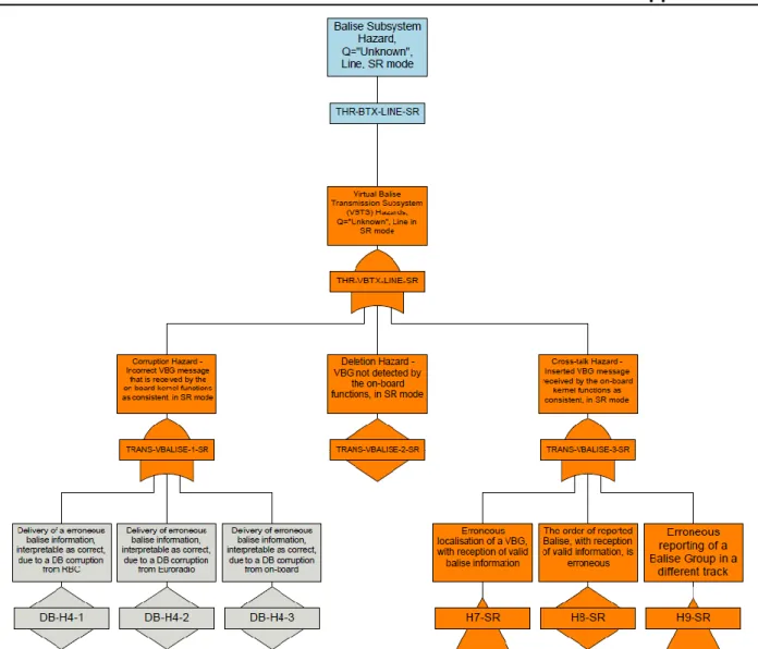
11.3.1 THR-VBTX-SR Apportionment
Figure 6 – The THR-VBTX-LINE-SR apportionment down to TRANS-VBALISE-1, 2, 3
FT Gate / Event Description Apportioned THR Remarks
THR-BTX-LINE-SR
Balise Subsystem Hazard in LINE, with SR Authorization (since Q_STATUS = «Unkown»)
0.67E-9/h -
THR-VBTX-LINE-SR
The Virtual Balise Subsystem Hazard in LINE, with SR Authorization
0.67E-9/h -
TRANS-VBALISE-1-SR
Corruption Hazard - Incorrect VBG message that is received by the on-board kernel functions as consistent, in SR mode
1E-11/h
Applicable only to the VBG stored information (i.e. user bits). Considered negligible with respect to VBALISE-2-SR and TRANS-VBALISE-3-SR.
As per NGTC D7.7 F [R11] and [R12].
`
FT Gate / Event Description Apportioned THR Remarks
TRANS-VBALISE-2-SR
Deletion Hazard - VBG not detected by the on-board functions, in SR mode
1E-10/h
This THR is allocated as per [R12]. It addresses the minimal hazardous probability of losing the first Information Point in SR mode.
TRANS-VBALISE-3-SR
Cross-talk Hazard - Inserted VBG message received by the on-board kernel functions as consistent, in SR mode
0.66E-9/h
THR considered as per [R12] allocating most of THR-VBTX-LINE-SR to insertion hazard instead of deletion.
DB-H4-1
Delivery of erroneous virtual balise information, interpretable as correct, due to a DB corruption from RBC
Negligible
New event with reference to NGTC.
Non-classed as hazard. Mitigated by RBC safe (i.e. SIL 4 compliant) design and development
DB-H4-2
Delivery of erroneous virtual balise information, interpretable as correct, due to a DB corruption from Euroradio
1E-11/h
New event with reference to NGTC.
100% of TRANS-VBALISE-1-SR, and conform to SUBSET-088 THR allocation to Euroradio Corruption Hazard.
DB-H4-3
Delivery of erroneous virtual balise information, interpretable as correct, due to a DB corruption from on-board
Negligible
New event with reference to NGTC.
Non-classed as hazard. Mitigated by On-board Kernel safe (i.e. SIL 4 compliant) design and development
H7-SR Erroneous localisation of a
VBG, with reception of valid balise information
0.33E-9/h
TRANS-VBALISE-3-SR is uniformly apportioned between H7 and H9 events. The FTA below H7 is analysed in § 11.3.2.
H8-SR The order of reported Balise, with
reception of valid balise
information, is erroneous
Negligible
Non-classed as hazard. The correct VB order is ensured by Odometry (designed as safe), which cooperate in the VB generation.
The correct order of reported VB shall be ensured by VBR design and development as well (see [R1]).
`
11.3.2 H7-SR Apportionment
`
FT Gate / Event Description Apportioned THR Remarks
H7-SR Erroneous localisation of a
VBG, with reception of valid balise information
0.33E-9/h
TRANS-VBALISE-3-SR is uniformly apportioned between H7 and H9 events
VBR-H7
Erroneous localisation of a VBG, with reception of valid balise information, due to failure within the on-board VBR function - VBG position error not correctly bounded
0.33E-9/h
New event, defined
analogously to BTM-H7 event of Subset-088. 100% contributing to H7-SR. Refer to ATP-ERR-GT-PL in NGTC D7.7 F DB-H7 Erroneous localisation of a VBG, with reception of valid virtual balise information, due to erroneous Track DB data preparation
Negligible
New event with reference to NGTC.
Considered negligible with respect to VBR-H7, since the data preparation of the Track DB is assumed compliant to a SIL4 function.
Refer to Note 1 below.
GNSS-MI GNSS integrity risk [(ATPE
>ATPL) and (TTA> X seconds)] 7.5E-06 / h
The GNSS Positioning integrity risk for Virtual Balise Detection, as per ITST 2018 [R12].
It can theoretically be achieved with Augmentation and RAIM.
INDEP-CHK Independent checks integrity
risk ~ 4E-05/h
The THR that the ERSAT-GGC Enhanced ERTMS architecture should
approximately meet to close the gap between GNSS-MI and VBR-H7 target. The precise THR allocation and control depends on the specific architecture design choices. Refer to Note 2 below.
The event is only renamed with respect to NGTC D7.7 F.
CHK-MDE-ERR
Erroneous estimate of minimum detectable error (fault-free) (MDE > Estimated MDE)
-The THR allocation is to be undertaken by the supplier. Gate only renamed with respect to NGTC D7.7 F
`
Define a procedure to safely address and perform the Track Database Data Preparation. The procedure shall be compliant to a SIL 4 function design. [ERSAT_GGC_D3.2_04]
Note 2: The independent checks are assumed to be based on GNSS independent cross-checks, for example:
Comparing the output of on-board Odometry sensors;
Comparing the code and phase measurement upon the pseudo-range;
Comparing the coherence between the Virtual Balise Detection and the track occupation the information.
The abovementioned strategies can be differently implemented by the single supplier. The upper bound of INDEP-CHK shall be implemented in compliance with the VBR-H7 value reported in the table above.
11.3.3 H9-SR Apportionment
`
FT Gate / Event Description Apportioned THR Remarks
H9-SR Erroneous reporting of a
Balise Group in a different track 0.33E-9/h
TRANS-VBALISE-3-SR is uniformly apportioned between H7 and H9 events
TR-ERR-SR Erroneous Track Discrimination 0.33E-9/h
100% of H9-SR.
Refer to RBC-FAIL-SR in NGTC D7.7 F
DB-H9-1 Erroneous (incoherent) validated
Track DB Negligible
New event, with reference to NGTC. It is considered negligible, since the Track DB validation is assumed safe. Please, refer to Note 1 below.
DB-H9-2
Erroneous reporting of a Balise Group in a different track, with reception of valid virtual balise information, due to a DB corruption from Euroradio
1E-11/h
New event with reference to NGTC.
The hazard contribution is as negligible as per Euroradio Corruption Hazard in SUBSET-088.
DB-H9-3
Erroneous reporting of a Balise Group in a different track, with reception of valid virtual balise information, due to a DB corruption from RBC
Negligible
New event with reference to NGTC.
Non-classed as hazard. Mitigated by RBC safe (i.e. SIL 4 compliant) design and development
DB-H9-4
Erroneous reporting of a Balise Group in a different track, with reception of valid virtual balise information, due to a DB corruption from on-board
Negligible
New event with reference to NGTC.
Non-classed as hazard. Mitigated by On-board Kernel safe (i.e. SIL 4 compliant) design and development
TMS-XCK-ERR Erroneous confirmation of train
position using TMS information Negligible
New basic event defined accordingly to procedure defined in § 5.6.2 of [R1], and applicable to in Line scenario as well
RBC-XCK-ERR Failure of RBC NID_ENGINE
coherency check (i.e. Train "Approximation")
Negligible
New basic event defined accordingly to procedure defined in § 5.6.1 2 of [R1], and applicable to in Line scenario as well
11.3.4 GNSS-MI Apportionment
`
FT Gate / Event Description Apportioned THR Remarks
GNSS-MI GNSS integrity risk [(ATPE
>ATPL) and (TTA> X seconds)] 7.5E-06 / h
The GNSS Positioning integrity risk for Virtual Balise Detection, as per NGTC D7.7 F and ITST [R12].
It can theoretically be achieved with Augmentation and RAIM.
FAULT-FREE
Ground segment Fault Free system integrity risk (without any failure in the system)
2.4 E-6/h
Allocation determined on the basis of translated SBAS APV-I performances in aviation [R12].
Considered as per NGTC D7.7 F and ITST [R12].
SIS-MI Integrity risk due to SIS MI 2.4 E-6/h
Allocation determined on the basis of translated SBAS APV-I performances in aviation [R12].
Considered as per NGTC D7.7 F and ITST [R12].
USER-MI Integrity risk due to user MI (local
effect on signal) 2.4 E-6/h
Additional allocation included for modelling Railway Environment effects on received signal [R12] Considered as per NGTC D7.7 F and ITST [R12].
IONO-UNDET Undetectable ionospheric
perturbation (out of worst iono model conditions)
-
Event as per aviation apportionment.
Position domain performances in railway environment to be proven by the supplier.
USR-SEG-ERR Out-of-bounds user segment errors(extreme multipath,noise, tropospheric errors)
-
These errors are those not mitigated by SBAS or VBR barriers protecting user against local feared events. Position domain performances in railway environment to be proven by the supplier.
UDRE-TAIL-EFF UDRE tails effects -
Event as per aviation apportionment.
Position domain performances in railway environment to be proven by the supplier.
`
FT Gate / Event Description Apportioned THR Remarks
Position domain performances in railway environment to be proven by the supplier. MULTIPATH Multipath at train antenna not
bounded by σ_multipath
belong to
[3.33E-9/h, 8E-7/h ]
Gate partially modified with reference to NGTC. Refer to § 11.3.4.1 for the THR range derivation
NLOS Undetected NLOS at train
antenna
belong to
[3.33E-9/h, 8E-7/h ]
Gate partially modified with reference to NGTC. Refer to § 11.3.4.1 for the THR range derivation PR-NOISE PR noise due to interference
near
train not bounded σ_noise
belong to
[3.33E-9/h, 8E-7/h ]
Gate partially modified with reference to NGTC. Refer to § 11.3.4.1 for the THR range derivation
USER-MPATH Severe Multipath at train antenna
-The frequency of this event is still under investigation. It will be consolidated in X2Rail
MPATH-DIAG Failure of MPATH detection and
exclusion
-The definition of the multipath detection mean (e.g. Railway RAIM algorithm) depends on the specific supplier design choices, but it shall be compliant to the platform safe design.
USER-NLOS NLOS at train antenna
-The frequency of this event is still under investigation. It will be consolidated in X2Rail
NLOS-DIAG Failure of NLOS detection and
exclusion
-The definition of the multipath detection mean (e.g. Railway RAIM algorithm) depends on the specific supplier design choices, but it shall be compliant to the platform safe design.
USER-NOISE Interference near train antenna
-The frequency of this event is still under investigation. It will be consolidated in X2Rail
ERR-NOISE-EST Erroneous σ_noise estimation
-The definition of the multipath detection mean depends on the specific supplier design choices, but it shall be compliant to the platform safe design.
Table 11 - The detail of the GNSS-MI apportionment
11.3.4.1. The Multipath, NLOS and PR-NOISE targets:
The THR allocation to the 3 events MULTIPATH, NLOS, PR-NOISE depends on the failure frequency of the safety functions mitigating the identified GNSS signal errors leading to a position failure (case where (ATPE >ATPL)), and the environmental effect frequency.
`
A risk of integrity occurs if an alert is not activated in dangerous cases (i.e. cases where the position is failed and the TTA value is exceeded). Today safety processes detecting such kind of errors are still in development and their performance may be expressed with a confidence level.
Therefore to allocate a THR to the 3 events MULTIPATH, NLOS, PR-NOISE, it can be considered, in a first vision, that these THRs take a value included in an interval to consider the evoked variability of the environment and the confidence level of the safety processes. So a THR interval can rather be allocated instead of a THR value.
Let THReq be the THR of the output event of an “OR” gate having in input three basic
events. This THR is such as THReq=THR1+THR2+THR3 , with here:
• THReq is associated to the event “USER-MI”
• THR1 is associated to the event “MULTIPATH”
• THR2 is associated to the event “NLOS”
• THR3 is associated to the event “PR-NOISE”
The objective of the optimisation problem is to compute the intervals of THRi
(i=1,2,3) such that THReq< 2.4E-6/h
Using a simple mathematical formulation of this problem, this leads to:
• Solve a linear systems of equations where the THReq of the output event is known to
lie in a specified range (here THReq< 2,4E-6/h)
• The variables are THRi (i=1,2,3)
To solve this problem, two methods can be given:
• To use the interval arithmetic to enable computation of intervals containing the elements of
the exact solution of THRi (i=1,2,3).
• To solve the linear interval system Ax = b where x and b are known to be in form of vector intervals using then Gaussian elimination and Krawczyk’s method.
Considering the first method, the INTLAB Matlab toolbox is used to solve the problem: A=[infsup(1,1) infsup(1,1) infsup(1,1)]
b=infsup(0.00000001,0.0000024) format long