• Aucun résultat trouvé

Improved False Causal Loop Detection in Polychronous Specificationof Embedded Software

N/A
N/A
Protected

Academic year: 2021

Partager "Improved False Causal Loop Detection in Polychronous Specificationof Embedded Software"

Copied!
29
0
0

Texte intégral

(1)

HAL Id: inria-00637582

https://hal.inria.fr/inria-00637582

Submitted on 2 Nov 2011

HAL is a multi-disciplinary open access

archive for the deposit and dissemination of sci-entific research documents, whether they are pub-lished or not. The documents may come from teaching and research institutions in France or abroad, or from public or private research centers.

L’archive ouverte pluridisciplinaire HAL, est destinée au dépôt et à la diffusion de documents scientifiques de niveau recherche, publiés ou non, émanant des établissements d’enseignement et de recherche français ou étrangers, des laboratoires publics ou privés.

Specificationof Embedded Software

Bijoy Anthony Jose, Abdoulaye Gamatié, Matthew Kracht, Sandeep Kumar

Shukla

To cite this version:

Bijoy Anthony Jose, Abdoulaye Gamatié, Matthew Kracht, Sandeep Kumar Shukla. Improved False Causal Loop Detection in Polychronous Specificationof Embedded Software. [Research Report] 2011, pp.28. �inria-00637582�

(2)

F E R M A T

Formal Engineering Research using

Methods, Abstractions and Transformations

Technical Report No: 2011-08

Abstract –

As opposed to single clocked synchronous programming paradigms, polychronous formalism allows specification of concurrent data flow computation on signals such that various data flows can evolve asynchronous with respect to each other. Explicit constraints and constraints implied by the syntactic structures impart certain intrinsic properties to models specified polychronously. One of the major steps in designing a synthesis engine for polychronous specifications is the characterization of specified models into categories such as inherently sequential or inherently multi-threaded. In this paper, we are concerned with sequentially implementable polychronous specification where computation is divided into a totally ordered sequence of logical instants. Data flow computation within an instant happens based on the implied data flow order. This order or data dependency often varies from one instant to another. Thus determining if there is an instant at which the data flow order forms a causal cycle is an important problem. In the current polychronous compilers, such as SIGNAL compiler and EmCodeSyn, this is solved without due effort, by rejecting any program which has a buffer-free structural cycle. However, a clocked dependency graph can be used to construct logical constraints representing the instants with a possible causal loop. The satisfiability of such constraints would imply that such a loop is realizable and hence the specification has a possible deadlock. The reachability of this instant with a given set of initial conditions would verify if the program should be rejected. In the past, the work on such constraints and their satisfiability has not been implemented even though for pure Boolean signals and clocks this could have been done using a satisfiability solver. With the advent to SAT modulo theory (SMT) solvers, this can now be extended to a more general class of specifications. Moreover, model checking on an abstraction of the specification can provide more information about the reachability of instants at which cyclic data dependency is realized. This paper presents an improved polychronous synthesis tool accepting a much larger class of specifications than could be done before. In our experimental results, we demonstrate the capabilities of our causality analysis methods and show that our synthesis tool performs better than previous strategies, including our own past work.

Improved False Causal Loop Detection in

Polychronous Specification of Embedded Software

Bijoy A. Jose, Aboulaye Gamatie, Matthew kracht and Sandeep K. Shukla

{bijoy,mwkracht,shukla}@vt.edu abdoulaye.gamatie@lifl.fr

(3)

I. INTRODUCTION

Instantaneous or causal loops, i.e., cyclic data dependency within an instant, have been a problem in all languages in the synchronous programming paradigm. Various solutions to the problem of detecting causal loops and non-realizable apparent causal loops, referred to as

false causal loop, have appeared in the literature of Esterel [1], Lustre [2], SIGNAL [3], and

hardware description languages. In general, the problem is undecidable because determining if a loop is realizable may be dependent on arbitrary data types, and arbitrary functions on such data. As a result, approximations have been proposed. To err on the side of the caution, due to false positives, a lot of correct programs are rejected by compilers. In the early days of synchronous programming, syntactic checks were used, leading to too many false causal loops. Since then, semantic analysis have been incorporated in many of the compilers. Unfortunately, in the polychronous programming literature, not a lot of attention has been paid to this problem beyond 1) syntactic detection rejecting all buffer-free loops as implemented in the Polychrony compiler [4] and 2) causal loop detection using nullity check of clock intersection in SIGNAL programs [5]. With the advent of SAT Modulo theory checkers, these approximations dealing with Boolean data types can be vastly improved. Also, the causal loop detection techniques can be extended to analyze nuances of polychronous calculus and thus detect falsity of apparent causal loops. In this paper, we revisit the problem of false causal loops in Polychronous specifications, and show how we solve this problem in our polychronous framework MRICDF [6].

Multi-Rate Instantaneous Channel connected Data Flow language (MRICDF) is a visual poly-chronous formalism, where actors communicate with each other through instantaneous channels while imposing restrictions on event occurrences on ports of actors [7]. The possibly infinite stream of events on a signal is called as epoch in MRICDF or clock in SIGNAL [8]. An epoch analysis step was proposed where a top-down approach is taken to construct a follower set. It is an ordered set of signals arranged according to their epochs in descending order. It is equivalent to a clock tree constructed bottom-up using clock calculus technique for SIGNAL programs. Epoch analysis is performed at the Boolean domain, where each signal is represented as a Boolean variable with true/false denoting the presence/absence of an event respectively. Beyond causality analysis, epoch analysis infers a signal with the largest set of events called the master

(4)

as the root node in the clock tree. The SIGNAL compiler Polychrony [9] considers an acyclic polychronous specification as sequentially implementable, if a hierarchic clock tree with root clock is found using clock calculus technique [10]. For EmCodeSyn [11], an acyclic MRICDF specification must have a master trigger and a follower set for sequential software synthesis [12]. The causality analysis techniques implemented by both these tools are limited by the intermediate representation formats used for software synthesis. We demonstrate their vulnerabilities with a few motivating examples in the next subsection. The improvements proposed in this work are not limited to our EmCodeSyn framework, and are applicable to other polychronous synthesis tools.

A. Motivational examples and problem statement

We introduce the problems addressed in this paper by giving polychronous specifications containing possible causal loops.

Example 1 (Causal loop detection): A polychronous MRICDF networkSpec1with its

equiv-alent SIGNAL program are shown in Figure 1. There are two Merge MRICDF actors M1 and

M2 which merge input streams with a higher priority given to first input port on occurrences of

simultaneous events. a M1

F

1 b process Spec1 = ( ? boolean a, e, clk; ! boolean b; ) ( | b := a default d %M1% | c := b+1 % F1% | d := e default c % M2% | a ^= when clk | e ^= when (not(clk)) |) where boolean c, d; end; M2 c d e 2 1 1 2 a ^= [clk] e ^= [-clk]

Fig. 1. Spec1: causal loop specification in MRICDF (left) and SIGNAL (right)

Merge actors (here M1 and M2) give priority to port 1 over port 2. An external signal clk

decides the flow of data in the specification. Whenclk is present and true (shown as [clk]),

there are events on a connected to M1 and not on e. Consequently, M1 ignores inputs on port 2,

which means the data does not flow through the entire loop as shown by the red dashed lines.

(5)

connected to M2 and not on a. Now, the flow of data is shown by dotted green lines. In both

cases, the edges of the data flow network loop, i.e., signals b, c and d are active. But, there

is no causal loop bcdb. Also, there is no possible input for the specification which

can lead to a causal loop.

Polychrony compiler and EmCodeSyn cannot synthesize sequential code for the program

Spec1 in Figure 1. A dependency cycle is reported between variables b, c and d. But, we

learned how the polychronous nature of the specification ensured a data dependent loop does not arise. The clock tree representation of Polychrony and the Boolean theory representation of EmCodeSyn are insufficient to determine implementability of such specifications.

Example 2 (Causal loop formed by clock and data constraints): A polychronous MRICDF net-workSpec2with its equivalent SIGNAL program are shown in Figure 2. There is aMergeactor

M1, a Sampler actor S1 and a Function actor F1 in the MRICDF network. The Sampler

actor S1 passes the value of any event atain onto a when the Boolean input trigger has a

true valued event. Functionactor F1 computes the sum of b andd. Two possible constraints

(C1,C2) are shown with C1 included as a part of SIGNAL code.

Constraint C1: ain ^= d ^= trigger Constraint C2: ain ^= d ^= [trigger]

a b

F

1 c d

S

1 ain trigger

M

1 process Spec2 = ( ? boolean trigger; integer ain, d; ! integer b; )

(| a := ain when trigger % S1% | b := a default c %M1% | c := b + d %F1% | ain ^= d ^= trigger |)%C1% where integer a, c; end; 1 2 Specification deciding epoch of trigger

Fig. 2. Spec2: Evaluating causal loop conditions with clock and data constraints

In the SIGNAL program Spec2, due to the clock constraint C1, a continuous stream of

events is guaranteed at signals ain, dandtrigger. Whentrigger signal is present with

af alse value, there is no event ata. Here, a causal loop (bcb) may be formed. In order

to avoid this situation, clock constraint C2 can be applied guaranteeing always true values at

trigger (represented as [trigger]). Since Merge actor has a higher priority for port 1, events at port 2 are ignored and thus a causal loop is avoided.

Polychrony and EmCodeSyn will reject Spec2 with constraint C1, accept Spec2 with constraint C2 and rightly so. If trigger is not an external input, rather a data computation

(6)

D1requiring Integer arithmetic ( say trigger := f alse when (ain >5 and ain <2)

default true), both tools will reject the specification. Here, trigger can be f alse only

whenain is greater than 5 and less than 2, which is impossible. But the intermediate structures of Polychrony and EmCodeSyn are not powerful enough to capture and evaluate these conditions. In fact, if code generation is forced on Polychrony, a causal loop (b → c → b) is warned. In summary, there is a need to move onto more expressive and powerful structures which expand the set of implementable polychronous programs using a software tool.

In a recent work, verification tools were shown to be efficient in software synthesis for generic computing algorithms [13]. Program guards are evaluated as verification problems to determine program execution. One popular verification tool, the SMT solver [14], is capable of evaluating theories of various data structures as motivated by Example 2. Recent developments in SAT and SMT solvers [15] have made their use in synthesis practical. Improving the synthesis time for Boolean theory-based synthesis is the second problem we address in this paper. We use a prime implicate generator [16] for master trigger identification. This generator has long synthesis time, making our tool impractical for larger designs. Enhancements in synthesis time have been achieved by optimizing MRICDF networks , thereby reducing the number of Boolean equations to be analyzed [17]. Other options include faster algorithms for prime implicate generation or pursuit of alternatives for prime implicate generator.

B. Our solution

In general, our contributions aim to enhance sequential software synthesis from polychronous specifications. For this purpose, we propose an extension to our recent work on using SMT solvers for sequential software synthesis [18]. In this work, we show how to perform time-efficient causality analysis by adopting a mix of verification tools for each causal loop problem. We also show that SMT solvers can be used to replace a time consuming prime implicate based implementation of our Boolean theory approach to synthesis. The techniques employed albeit related to polychronous formalisms, are applicable in other embedded software synthesis tools which follow synchronous MoCs.

In particular, we distinguish the following two issues:

1) Expressive causality analysis for polychronous specification employing verification tools. Data domain constraints and non-realizability of a clock constraint at which a data

(7)

depen-dence loop is formed cannot be properly utilized in the absence of expressive theory of data domains, arithmetic, and propositional satisfiability. In existing tools, the absence of these techniques leads to overly pessimistic compilation, rejecting many polychronous specifi-cations with non-realizable causal loops. A new SMT based approach is used to check actual data dependencies in causal loops. We distinguish different types of causal loops in polychronous specification and a heuristic tailored for faster detection is implemented which uses specific verification techniques.

2) Shortening the code synthesis time. The Boolean theory approach of testing for root clock (or master trigger) is implemented by interfacing an SMT solver. The synthesis time is shown to be significantly better than a direct prime implicate computation technique to find root clock.

a) Outline: This paper is organized as follows. Section II reviews the existing work on

soft-ware synthesis from polychronous specification and the different causal loop analysis techniques related to synchronous MoC. In Section III, we provide the background information on poly-chronous formalism and explain our Boolean theory based synthesis technique. Section IV deals with the causality analysis improvements proposed and experiments conducted with EmCodeSyn. Section V explains how software synthesis is performed using SMT solvers. Experimental results are provided in respective sections to analyze the efficiency of each contribution. The paper is concluded in Section VI.

II. RELATEDWORK ON SOFTWARE SYNTHESIS FROM SYNCHRONOUS SPECIFICATION

We cover the existing work on software synthesis from polychronous specification and the different causal loop analysis techniques related to synchronous MoC. At the heart of syn-chronous MoC is the synchrony hypothesis [19] that assumes instantaneous computations and communications between actors. In other words, the time to compute and communicate is negligible compared to the time between two adjacent events on a signal.

Different programming languages exist which follow the synchronous model of computation, such as Esterel , Lustre and SIGNAL. Esterel is an imperative synchronous programming language where computations are performed as reaction steps [20], [21]. Testing for presence of an event on a signal is allowed and accordingly specific computations are selected for execution. The software synthesis tools that accept concurrent Esterel specifications such as

(8)

Esterel Studio [22] and Columbia Esterel Compiler [23] can generate optimized RTL or C code from the different possible orders of execution. Quartz [24] is a variation of Esterel language which has its own synthesis and verification environment called Averest [25]. Lustre on the other hand is a declarative synchronous language where specifications are expressed in terms of data flow equations [26]. In Lustre programs, every signal clock is analyzed in reference to a single simulation clock. Here, multi-rate signals have to be expressed as undersamplings of the simulation clock. A software synthesis tool based on Lustre is the SCADE suite [27], which has been used in the avionics field. Also available is a higher order functional variant of Lustre known as Lucid Synchrone [28].

A recent work [10] has summarized sequential synthesis condition of SIGNAL programs as follows: a compilable and hierarchic SIGNAL program is endochronous. In other words, a sequentially implementable SIGNAL specification would not contain causal loops and its clock tree would be hierarchic with a root clock. One of the goals of our work is to improve causal loop detection for SIGNAL/MRICDF formalism. There has been a significant amount of work in this direction for hardware circuits and synchronous systems. An early work on the analysis of cycles in combinatorial circuits uses ternary symbolic simulation method [29]. This work was extended later to sequential circuits and to Esterel language. ‘Constructivity’ [30] was proposed, which considers a circuit to be acyclic if and only if for every external input a unique value can be determined for each internal and output signal. A sequential circuit is constructive if the combinational part is constructive for given input values and the latch outputs are restricted to reachable states [31]. A heuristic was proposed where ternary symbolic simulation is performed to see if the set of unstable states is empty. If so, the circuit is declared constructive. Otherwise, a reachability analysis is done to see if any of the unstable states is reachable from a sequence of given inputs. Our analysis of false causal loops is similar to this work, since we check for a possible input sequence to activate the causal loop condition.

Checking constructivity as a Satisfiability problem was proposed in [32]. In their formal verification system, a set of internal signals are identified, which would eliminate all syntactic cycles. A constructivity-SAT formula for a cycle is defined to perform reachability analysis. In addition, an error path from initial state to a state where the cycle is true is determined. Thus the cycle analysis has been extended to finite non-Boolean types. In Esterel, instantaneous termination due to incorrect programs or schizophrenic programs was analyzed in [33]. A

(9)

program is declared instantaneous iff the execution completes in a single reaction. The analysis of causal loops using using SAT techniques was suggested, but was not experimented with. Some provable correct Esterel programs were noted to be rejected due to incomplete causality analysis. Other prominent works on causality analysis provide optimizations for causality elimination [34] and applying standard logic synthesis techniques [35]. A common thread in these works is isolation of specific properties useful for causality analysis in the respective synchronous languages or the use of verification techniques such as model checking [36], [37].

In SIGNAL, a recent work [38] has experimented dead code detection based on computation of intervals for values of signals. Parts of a program can be rejected if the expected values did not fall in the computed interval. Another work [39] includes translation of polychronous specifications into synchronous ones for causality analysis. The work aimed at embedding a polychronous specification in SIGNAL/MRICDF form into a synchronous Quartz model to utilize the capabilities of Averest environment. The current work is an extension of [18], where causality analysis and synthesis using SMT solvers was originally proposed. These were based on our Boolean theory based alternative to clock calculus for performing software synthesis.

III. SOFTWARESYNTHESIS FROM POLYCHRONOUS FORMALISM

For a better understanding of our work, we provide some preliminaries on synchronous structures and a background into our visual polychronous formalism, synthesis technique, and code generation tool.

A. Preliminaries on synchronous structure

We present first some basic definitions about the synchronous model of computation using synchronous structures as defined in [40].

Definition 1 (Events, Signals): An event is an occurrence of a value. A signal is a totally ordered set of events.

For a signal x, an event on x is denoted by ex and the set of all events on x is denoted by E(x).

The set of all events in a specification is denoted by Ξ.

Definition 2 (Synchronous structure): The pair (Ξ,≪) is a synchronous structure if and only

if Ξ is a non-empty set of events and ≪ is a preorder on Ξ such that ∀x ∈ Ξ · {y ∈ Ξ | y ≤ x}

(10)

• (equivalence) x ∼ y ⇔def x ≪ y ∧ y ≪ x

• (precedence) x < y ⇔def x ≪ y ∧ x ≁ y

• (partial order) x ≤ y ⇔def x < y ∧ x = y

Definition 3 (Instant): If the set of all events Ξ is partitioned using the equivalence relation

∼, equivalence classes containing events that are synchronous with each other are formed. Each

of these equivalence classes is called an instant, i.e., Υ = Ξ/ ∼.

Any event ex on a signal x belongs to an instant of a synchronous structure, say S ∈ Υ. We

denote it as ex ⊲S.

Definition 4 (Epoch): The epoch of a signal is a possibly infinite set of instants where that signal has events.

For a signal x, I(x) or bx are used to denote its epoch. An epoch is also known as clock of

a signal in SIGNAL terminology. The synchronous relations defined on events in signals are extended as relations between epochs of signals.

Definition 5 (Synchronous signals): If two signals have the same epoch , they are said to

be synchronous. For two synchronous signals x and y, I(x) = I(y). Both signals have events

belonging to the same instant S, where S ∈ Υ. ∀S ∈ I(x) ⇔ S ∈ I(y).

In SIGNAL, synchronous nature of two signals x, y can be denoted by x ∧

= y.

B. MRICDF formalism and the Boolean theory based sequential synthesis strategy

The four basic actors of MRICDF formalism are Function, Buffer, Sampler and

Merge. They are derived from SIGNAL primitives and have the same epoch constraints as

mentioned in Figure 3. A few sample traces demonstrating each of their operation is shown in a table near each actor. The symbol⊥ denotes absence of an event in a signal. The Function

actor imposes an epoch equality for input-output signals. It performs user-specified computations within an instant. The Buffer actor acts as a single input-output storage, imposing epoch equality for input and output signals. On occurrence of an input event, its value is stored and the stored value from previous instant is given as output.Sampler actor performs a downsampling operation of its first input epoch. On an occurrence of true value on its Boolean second input

port (represented as[b]), the event at first input is sent to the output. The Mergeactor combines input streams from two input ports with a higher priority for the first input port. It performs an upsampling operation on the epochs of its inputs.

(11)

x = Function (a+b)

x = Sampler (a,b) x = Merge(a,b) x

1 2 1 1 1 3 3 x 1 t 3 5 t f 2 x = Buffer (a,8) x 1 8 2 2 1 3 ŏ ŏ ŏ ŏ ŏ ŏ ŏ ŏ ŏ ŏ ŏ a a b a b ŏ

SIGNAL x := a+b SIGNAL x := a$ init 8

SIGNAL x := a when b SIGNAL x := a default b EPOCH I(x) = I(a)ŀ I([b])

EPOCH I(x) = I(a) = I(b) EPOCH I(x) = I(a)

EPOCH I(x) = I(a)ʐI(b)

M b x B init 8 x F(a,b) a b x S a b x a a x 1 2 3 2 3 3 ŏ ŏ a b ŏ 3 5 6

Fig. 3. MRICDF actor primitives

MRICDF Actor Epoch relation Boolean Equations

Function F(2, 1) I(x) = I(a) = I(b) bx= ba, bx= bb

Buffer B I(x) = I(a) bx= ba

Sampler S I(x) = I(a) ∩ I([b]) bx= ba∧b[b], bb= b[b]∨b[¬b], b[b]∧b[¬b]= f alse

Merge M I(x) = I(a) ∪ I(b) bx= ba∨bb

TABLE I

MRICDFACTOR PRIMITIVES AND THEIR EPOCH CONSTRAINTS

The epoch relations of each MRICDF actor can be represented in Boolean domain as shown in Table I. Here, the presence and absence of any signal x at any arbitrary instant is represented

bytrue and f alse values respectively on bx. The instants where a signal of Boolean type, sayx,

is present having a true value is denoted by b[x] and instants where x is present having a f alse

value is denoted byb[¬x]. So, for such a signalx, we know bx = b[x]∨b[¬x]andb[x]∧b[¬x]= f alse.

Once a given MRICDF specification is translated to Boolean domain according to Table I, the root clock, or in our terminology the master trigger, has to be found. It is the signal which is present at every instant of the MRICDF network, and will be used as a reference to start computation at every instant.

(12)

as its set of events and Υ the set of all instants of the MRICDF network. For each S ∈ Υ, if

there exists an event et ⊲S, then t is the master trigger for M .

We have proposed a test for detecting the existence of a master trigger signal working in the Boolean domain. This involves checking for the presence of any other signal when a master trigger candidate signal is absent. We remove those instants where no signal is present by adding a Boolean equation stating that the disjunction of all signal Boolean variables istrue. This avoids

the trivial solution to the system of Boolean equations (all Boolean variables are false).

The system of Boolean equations defines a theory which has all the satisfying assignments for the system. A disjunctive clause belonging to the theory is an implicate of the theory. If the disjunctive clause is not part of any other disjunctive clause, it is a prime implicate of the theory. If the prime implicate clause is a single positive Boolean literal bt, we know that the

bt has to be true for any arbitrary instant. This represents the presence of the signal t in any

arbitrary instant of the MRICDF network, which is the definition of the master trigger signal. Thus, testing for a prime implicate which is a single positive Boolean literal, is the same as testing for master trigger signal in an MRICDF network.

Theorem 1 (Test for Master Trigger signal): A signalx in an MRICDF network M is a

mas-ter trigger, if and only if the corresponding Boolean variable bx in the system of Boolean

equations BM has the property that if bx is false, every other variable is false.

The proofs for master trigger test is available in [7]. If an MRICDF network has a master trigger (or multiple master trigger signals with same epoch), the next step is to identify a deterministic order of execution. This would involve identifying the signals in the order of descending epoch and a means to compute them from previously identified signals. If the master trigger Boolean variable bx is set to true, a simplified system of equations representing the

instants of the remaining signals is obtained. Here, a prime implicate clause may be found which represents all instants of the simplified MRICDF network. It might consist of multiple positive literals (say (by+ bz)), signifying that either y or z have events in all instants of the simplified

MRICDF network. Now, by and bz are set to true to get a simplified system of equations, and

prime implicate steps are repeated. During this process, each prime implicate result is identifying signals have a lower epoch than those found from the previous run. Each prime implicate result provides signals that are elements of the follower set, if they are computable from already known signals in the follower set.

(13)

Eventually a complete follower set will be found for a synthesizable program which is a set of elements containing all the signals in the system. This is identical to building a clock hierarchy where the nodes are signals found as prime implicates and the edges are relations between them with already computed nodes. Together, the causal loop detection, master trigger identification and the follower set form our MRICDF synthesis condition. More details on follower set and synthesis conditions can be found in [12].

C. EmCodeSyn project and the use of verification tools for synthesis

EmCodeSyn is a visual framework for capturing polychronous specifications as MRICDF networks and generating sequential C code [11]. The visual interface and design methodology of EmCodeSyn is shown in Figure 4. The captured MRICDF network is stored in a Network Information File (NIF) file which can also be reused once stored in a library. In the Epoch Analysis step, the NIF of a design is put through causality analysis to find causal loops. If the network passes this step, Boolean equations are produced in Conjunctive Normal Form (CNF). An external prime implicate generator computes the prime implicates of the Boolean system formed from MRICDF network and a single positive literal is identified as the master trigger signal. If there is no master trigger signal, exogenous information in the form of epoch constraints have to be provided to construct a master trigger signal. Later, a follower set is built after an iterative prime implicate generation process. Once the follower set is complete, the MRICDF network is declared as sequentially implementable by EmCodeSyn. Now code generation takes place, where three C files represent the computation in the order of execution prescribed by the follower set. The dashed boxes represent the extensions we propose to the EmCodeSyn methodology and their details are explained later in the paper.

Identifying every element of the follower set involves an iteration of the external prime implicate generator. Each run consists of computing all possible prime implicates (PI) since the PI generator cannot identify a master trigger signal or clause. This results in high synthesis time. One optimization was actor elimination technique (AET) which decreased the number Boolean equations fed to the prime implicate generator, thus reducing synthesis time [17].

The synthesis time was considerably reduced by better PI generators and our optimization technique [12]. Nevertheless, for larger examples, finding all possible prime implicates leads to a long synthesis time. An intelligent master trigger detection process was required instead

(14)

Prime Implicate generation Epoch Analysis Boolean Equations Epoch/Data Equations Code Generation NIF Follower Set Generation Exogenous rate constraints SMT Solver/ Model checker SMT Equations Exogenous rate constraints + initial conditions Follower Set Generation Prime Implicate results Master trigger candidates + results Follower Set Follower Set Main File Header File Function Definition File

Fig. 4. Visual Interface and design methodology of EmCodeSyn

of a non judicious all-at-once PI generation. Once a master trigger is identified, the process had to terminate and intelligent choices had to be made on which candidate to test first. All of this pointed to exploring alternatives to the black box external prime implicate generator. SMT solvers were found to be a likely option in [18]. Hence, posing the test for master trigger as a satisfiability problem and evaluating the performance of the two master trigger detection strategies was performed in this work.

IV. CAUSAL LOOP DETECTION ON POLYCHRONOUS SPECIFICATIONS

Among the tools adopting a polychronous MoC, Polychrony and EmCodeSyn analyze clock (or epoch) relations in specifications to determine if a causal loop exists. We differentiate the kinds of causal loops in polychronous specifications and explain how we improve the existing loop detection techniques.

Definition 7 (Topological Loop): A polychronous specification is said to contain a topological

loop provided the specification consists of a set of actors (i)a1, a2, .., an, such that an output port

ofan is connected to an input port ofa1; and (ii) for all actors a1, a2, .., an−1,∀i ∈ {1..(n − 1)},

an output port of the ath

i actor is connected to an input port of the athi+1 actor.

A topological loop containing a buffer actor does not propagate data instantaneously. So, a buffered loop is not to be rejected.

Definition 8 (Buffered Loop): A topological loop where at least one of the actors in the loop

(15)

If a software synthesis tool is able to locate a buffer free topological loop, epoch constraints need to be evaluated to know if there exists an instant for the network where a cyclic data dependency happens. In Polychrony, causality analysis step checks for buffer-free loops where the signal clocks in the loop are active. In other words, SIGNAL programs are rejected if there exists a logical instant where clocks of signals in a buffer-free topological loop of a program are active.

Definition 9 (Apparent Causal Loop): Consider a polychronous specification with a

topolog-ical loop containing signals x1, x2, .., xn having event sets E(x1), E(x2), .., E(xn) respectively.

The topological loop is an apparent causal loop, if and only if, it is not a buffered loop

and there exists an instant where all signals in the topological loop have an event. S ∈ Υ,

∀n

i=1, ∃e ∈ E(xi) ∧ e ⊲ S.

Spec1 is a program rejected after causality analysis in Polychrony since the signals b, c

and d form an apparent causal loop. Current versions of EmCodeSyn will do the same by detecting a possible logical instant (bb∧ bc∧ bd= true) resulting in an apparent causal loop. Due

to the nature of primitives such as Merge and default where a lower priority input might get ignored, a signal with an event does not mean there exists a causal loop with cyclic data dependency. We have demonstrated this using our example Spec1.

Definition 10 (False Causal Loop): Consider an apparent causal loop with signalsx1, x2, .., xn

having event sets E(x1), E(x2), .., E(xn) . An apparent causal loop is considered to be a false

causal loop, if and only if, for no instant in Υ, there exists a data dependency between events

en ∈ E(xn) with the events e1 ∈ E(x1) and for signals x1, x2, .., xn−1 there exists a data

dependency between events ei ∈ E(xi) with the events ei+1 ∈ E(xi+1).

Definition 11 (True Causal Loop): A true causal loop is an apparent causal loop which is not a false causal loop.

If the edges of a loop have events that never happen on the same logical instants, it is a false causal loop. A reason for incorrect rejection of programs due to false causal loops is the weakness of intermediate structures used for analysis. Clock analysis alone cannot entirely guarantee pres-ence of an event, due to dependency on values of functional computation units as demonstrated by our example Spec2. Neither clock calculus of Polychrony nor Boolean epoch analysis of EmCodeSyn can fully capture the actual data dependencies in their intermediate structures. We believe satisfiability modulo theories are capable of accommodating these requirements. Hence,

(16)

M

SIGNAL : x := a+b (assert (= cx ca) ) (assert (= cx cb) )

(assert (or (and cx (= x (+ a b) )) (not cx) )

SIGNAL : x := a when b

(assert (ite (and ca cb (= b true) ) cx (not cx))) (assert (or (and cx (= x a)) (not cx) ) )

SIGNAL : x := a$ init y (assert (= cx ca) )

(assert (or (and cx (= x y) (not cx) ))

SIGNAL : x := a default b (assert (ite (or ca cb) cx (not cx) ) ) (assert (or (and cx ca (= x a))

(and cx cb (not ca) (= x b)) (not cx)) )

(assert (ite ca M1dep1 (not M1dep1) ))

(assert (ite (and cx cb (not ca)) M1dep2 (not M1dep2)))

a b x B init y a x F(a,b) a b x S a b x

Fig. 5. SMT equations for MRICDF/SIGNAL primitives

they are chosen to distinguish between true and false causal loops.

A. Detection of true causal loops using SMT solvers

Satisfiability (SAT) of a Boolean formula implies there exists a solution to the encoded problem. Satisfiability Modulo Theory (SMT) extends SAT by checking satisfiability of formula over multiple theories such as Boolean, Integer and so on [14]. Our chosen SMT solver Yices version 1.0.29 has a representation format which uses assertions with other common operators. The SMT representation of MRICDF/SIGNAL primitives is summarized in Figure 5.

A signal xis encoded by an epoch variable cx of Boolean type and a data variable x of same

type as the signal. The epoch equations of Function and Bufferactors are shown as direct equations of input and output epoch variables in Figure 5. For Sampler and Merge, epoch equations are represented in a conditional if-then-else statement. Let us discuss Mergeactor in detail, where the epoch equation is of the form ‘if any of the input epoch variables are true, then

output epoch variable is true, else output epoch is false’. For data equations, the appropriate

data dependency is chosen according to input firing conditions. In Merge data equation, the respective data dependencies are chosen according to the output variable value ofcx along with

the presence or absence of input epoch variables ca and cb. To make the analysis of cyclic

dependencies easier, we put additional data dependency variablesM 1dep1 and M 1dep2 to show

the data dependency between input ports of the Merge actor with the output port. Note that only one among the data dependency variables can be true in a logical instant. This will help in determining flow of data in Merge actor along with favorable clock conditions in a loop.

(17)

Theorem 2 (True causal loop detection procedure): Given an MRICDF networkM represented

by the SMT formula setSM and a set of causal loop candidates C represented by the SMT formula

SC, ∀SCi ∈ SC, if SM, SCi true, then the MRICDF network has a true causal loop SCi .

Proof sketch: For an SMT formula to be satisfiable, there exists at least one valid assignment

to all the variables in the formula. The SMT formula set SM is representative of any arbitrary

instant P ∈ Υ of the MRICDF network M . The new SMT formula SM, SCi is representative of

all instants of MRICDF network where causal loop condition exists, denoted by Υi.

To prove that a given causal loop condition Si

C is a true causal loop, we need to prove that

any instant L where Si

C holds, is in Υ. If SM, SCi true, the SMT solver result is satisfiable.

There exists at least one valid assignment to all the variables in the formula, or one instant of the MRICDF network with the causal loop. Hence it is a true causal loop (Υi 6= φ). If

SM, SCi f alse, the SMT solver result is unsatisfiable. This means there is no valid assignment

to the variables in the formula. In other words, there does not exist any instant where the causal loop condition holds. Hence, Si

C represents a false causal loop (Υi = φ).

The SMT representation for Spec1in Figure 1 is given in Figure 6 (a). All signal definitions are of Boolean type and some are omitted in the figure. A triviality condition is added after the translation to remove the stuttering instant where no events can occur. Assertion 10 restricts the SMT equations to those instants where at least one signal has an event. Assertion 11 represents the causal loop condition under test. An UNSAT result is obtained from the SMT solver confirming the candidate to be a false causal loop.

The SMT representation for Spec2 with the clock constraint C1 and data computation

for trigger signal is shown in Figure 6 (b). Due to the clock constraint, a continuous

stream of events is guaranteed at ain, d and trigger. The data computation constraint

D1 trigger := f alse when (ain >5 and ain <2) default true is implemented

using three MRICDF actorsF2, S2,andM2. The apparent causal loop (b→c→b) is realizable only when a f alse value is obtained at trigger. An UNSAT result is obtained verifying it to be false causal loop. When the data computation constraint is altered to trigger := f alse

when (ain >0 and ain <2) default true, we did obtain a SAT result, reaffirming

the possibility of a true causal loop.

Presence of a true causal loop does not mean the generated code will encounter the causal loop condition during execution. The realizability of causal loop condition using SMT technique does

(18)

(set-evidence! true) (define ca::bool) (define a::bool) (define cb::bool) (define b::bool) .. (define cclk::bool) (define M1dep2::bool) (define M2dep2::bool) ;;M1 b := a default d

1 (assert (ite (or ca cd) cb (not cb)))

2 (assert (or (and cb ca (= b a))(and cb cd(not ca)(= b d)) (and (not cb)(not ca)(not cd))))

;;M2 d := e default c

3 (assert (ite (or ce cc) cd (not cd)))

4 (assert (or (and cd ce (= d e))(and cd cc(not ce)(= d c)) (and (not cd)(not ce)(not cc))))

;;F1 c = b 5 (assert (= cc cb))

6 (assert (or (and cc (= c (not b))) (not cc))) ;;External Clock Constraints

7 (assert (= cclk (or ca ce)))

8 (assert (ite (and cclk (= true clk)) (= ca true)(= ca false))) 9 (assert (ite (and cclk (= false clk)) (= ce true)(= ce false))) ;;Triviality Condition

10 (assert (= (or ca ce cclk cd cc) true)) ;;Causal loop condition

11 (assert (and cb cc cd M1dep2 M2dep2)) (check)

::S1 a := ain when trigger

1 (assert (ite (and cain ctrigger (= trigger true)) ca (not ca) )) 2 (assert (or (and ca (= a ain)) (not ca) ))

::M1 b := a default c

3 (assert (ite (or ca cc) cb (not cb)))

4 (assert (or (and cb ca (= b a)) (and cb cc (not ca) (= b c))(not cb))) 5 (assert (ite ca M1dep1 (not M1dep1) ))

6 (assert (ite (and cb cc (not ca)) M1dep2 (not M1dep2)) ) ;;F1 c := b+d

7 (assert (= cc cb)) 8 (assert (= cc cd))

9 (assert (or (and cc (= c (+ b d) )) (not cc) )) ;;F2 f2out := ain >5 and ain <2 :D1 10 (assert (= cf2out cain))

11 (assert (or (and cf2out (ite (and (> ain 5) (< ain 2)) (= f2out true) (= f2out false))) (not cf2out))) ;; S2 s2out := false when f2out : D1

12 (assert (ite (and true cf2out (= f2out true)) cs2out (not cs2out))) 13 (assert (or (and cs2out (= s2out false)) (not cs2out) )) ;; M2 trigger := s2out default true :D1

14 (assert (ite (or cs2out true) ctrigger (not ctrigger) )) 15 (assert (or (and ctrigger cs2out (= trigger s2out))

(and ctrigger true (not cs2out) (= trigger true) ) (not ctrigger))) ;;External Clock Constraints C1

16 (assert (= cain cd)) 17 (assert (= cain ctrigger)) ;;Triviality Condition

18 (assert (= (or ca cb cc cd cain ctrigger cs2out cf2out) true)) ;;Causal loop condition

19 (assert (and cb cc M1dep2))

(a) Spec1 : A false causal loop (a) Spec2 with constraints C1 & D1 : A true causal loop

Fig. 6. Distinguishing between causal loops using SMT solvers

not check if the MRICDF network can arrive at the state where the causal loop conditions hold, from a given initial state. Spec3, a modified version of the MRICDF network Spec2, where clock constraintC1 is applied and thetrigger signal is determined by another computation is shown in Figure 7 (a). Two incremental buffered countersxandyare shown with different initial values. Their increment operation is dependent on two signals having the same epoch, thereby equating the number of increments on them. The trigger signal is set to f alse, forming the

true causal loop (b→c→b) only whenxandyhave the same value. With the initial conditions being different and the number of increments being the same, the true causal loop condition is not reachable. The SMT technique can identify the true causal loop, but cannot predict if the loop will ever occur in the course of execution of the generated code. Additional reachability analysis using model checkers is required for this purpose. The causal loop types and the set of tools that are capable of detecting each of them is shown in Figure 7 (b). Current versions of Polychrony and EmCodeSyn are capable of identifying only up to apparent causal loops.

(19)

process Spec3 = ( ? integer ain, d;

! integer b; )

(| a := ain when trigger %S1%

| b := a default c %M1%

| c := b + d %F1%

| ain ^= d ^= trigger %C1% | x := (x$ init 1 + 1) when ^ain default 0 | y := (y$ init 0 + 1) when ^d default 0 | trigger := false when ( x == y) default true |)

where integer a, c, x, y; boolean trigger; end;

(b) Causal loop types and tools used for their detection EmCodeSyn + Model checker EmCodeSyn+ SMT solver EmCodeSyn or Polychrony Loop detection algorithm Topological loop

True causal loop

Reachable True causal loop Apparent causal loop

(a) Spec3: Polychronous specification for reachability test

Fig. 7. Reachability test for polychronous specification and causal loop types

EmCodeSyn is now automated with SMT solvers and model checkers to verify the presence of true causal loop and reachable true causal loop respectively.

B. Reachability of true causal loops

A recent work has shown how to embed polychronous specifications into synchronous ones in the form of MRICDF/SIGNAL to Quartz conversion [39]. The Averest tool was used to generate smv files from Quartz programs to determine if causal loops are constructive. A few of the Quartz representations for MRICDF actors are shown in Figure 8. MRICDF clock inputs are always represented as read only inputs (denoted by ?) from the environment, while MRICDF output signals are treated as read-write type, since they are written and read from modules. The imperative style code has the functionality of an actor (say MergeInt) expressed as epoch and data constraints. Primitive actors are instantiated, while clock or triviality conditions are expressed as ‘assume’ statements. More information on embedding polychronous processes into synchronous modules is available in [39].

The example Spec2 with constraint C1 can be represented as a Quartz program as shown

in Figure 9 (a). The standard actors M1 and S1 are instantiated from a library and the custom

F1 actor is part of the ‘loop’ in Quartz code. The clock constraints and triviality conditions are represented as ‘assume’ statements, while the apparent causal loop is represented as ‘assertion

(20)

module BufferBool(

event bool ?clk_i, ?i, ?clk_o, o, bool ?init) { bool q = init loop { if (clk_i) { next(q) = i; o = q; } assume(clk_o == clk_i); pause; } } module MergeInt(

event bool ?clk_i1, event int{128} ?i1, event bool ?clk_i2, event int{128} ?i2, event bool ?clk_o, event int{128} o, event bool dep1, dep2 )

{ loop { if (clk_i1) {

o = i1;

dep1 = true; dep2 = false; } else if (clk_i2) {

o = i2;

dep1 = false; dep2 = true; } }

assume ((dep1 & dep2) == false); assume( clk_o == (clk_i1 | clk_i2)); pause;

} }

module SamplerInt (

event bool ?clk_i1, event int{128} ?i1, event bool ?clk_i2, ?i2,

event bool?clk_o, event int{128} o) { loop {

if(clk_i2 & i2 & clk_i1){ o = i1; } assume((clk_i2&i2&clk_i1) == clk_o); pause; } }

(a) Buffer Boolean (b) Merge Integer (c) Sampler Integer

Fig. 8. Quartz modules for MRICDF/SIGNAL primitives

loop and if it can be reached. Its equivalent representation A2 has been found to be more time

efficient with the Cadence SMV model checker [41]. Reachability is not an issue for Spec2

since there are no buffers in the specification. There are no initial conditions and no transitions between states for Spec2. In Spec3, where trigger is a computation based on a buffer output, both initial conditions and possible transitions matter. Figure 9 (b) shows a shortened Quartz representation of Spec3. The same assertion is posed as the model checking problem and it is verified that the true causal loop is not reachable with the given initial conditions. It was also verified that with identical initial values on x and y, or with favorable increment counts, the true causal loop was reachable.

The relative advantage of model checking approach as opposed to SMT approach is in reach-ability analysis of the causal loop state. Given a set of initial conditions, our MRICDF/Quartz transformation tool provides an infrastructure to see if the apparent causal loop is a true causal loop and also if it is reachable. The model checking time for Spec2amounts to a few seconds, whereas SMT technique can perform true casual loop evaluation for Spec2 in a matter of milliseconds. Table II summarizes the time required to detect causal loops in MRICDF networks. [42] contains more information on the functionality of each MRICDF network. There are no restrictions on Integer variable size, but certain operations such as multiplications are not possible in SMT format. The number of actors in each network, the Boolean and Integer buffer counts are shown in columns 2,3, and 4 respectively. We add a simple 2 actor false causal loop (FCL) to each of these networks for computing the FCL detection time. Similarly a true causal loop

(21)

(a) Generated Quartz program for Spec2 (b) Generated Quartz program for Spec3

import Signal.*; module Spec2 (

event bool ?clk_a, event int{128} a, ...

event bool ?clk_trigger, event bool ?trigger, event bool M1dep1, M1dep2 )

{ M1: MergeInt (clk_a, a, clk_c, c, clk_b, b, M1dep1, M1dep2); ||

S1: SamplerInt(clk_ain, ain, clk_trigger, trigger, clk_a, a); || loop{ //F1 functionality if(clk_b) c = b+d; assume(clk_b == clk_c); //F1 constraint assume(clk_c == clk_d); //F1 constraint assume(clk_ain == clk_d);// clock constraints 1 assume(clk_d == clk_trigger);// clock constraints 1 //assume(clk_trigger -> trigger); // uncomment for constraint2 //triviality condition

assume( (clk_a |clk_b |clk_c |clk_d | clk_ain |clk_trigger) == true); pause;

} } satisfies {

A1: assert E F (clk_b & clk_c & M1dep2); A2: assert A G ((!clk_b) | (!clk_c) | (!M1dep2)); }

import Signal.*; module Spec3 (

event bool ?clk_a, event int{128} a, ..

event bool M4dep1, M4dep2, .., M1dep1, M1dep2 ) S1: SamplerInt(cain, ain, ctrigger, trigger, ca, a); ||

M1: MergeInt(clk_a, a, clk_c, c, clk_b, b, M1dep1,M1dep2); ||

B1: BufferInt(clk_$x, $x, clk_PlusX, PlusX, 1); ||

B2: BufferInt(clk_$y, $y, clk_PlusY, PlusY, 0); .. loop{ if( clk_c ) //F1 c = b+d; assume ( clk_c == clk_b ); assume ( clk_c == clk_d ); if( clk_x ) //F2

{if (x ==y) xyeq = true;} assume ( clk_x == clk_y ); assume ( clk_x == clk_xyeq ); ..

assume(clk_ain == clk_d);// clock constraints 1 assume(clk_d == clk_trigger);// clock constraints 1 //Triviality condition

assume( (clk_a | clk_b |«. clk_trigger) == true); pause;

} } satisfies {

A1: assert A G ( (!clk_b) | (!clk_c) | (!M1dep2) ); }

Fig. 9. Quartz representation ofSpec2and Spec3

(TCL) is added to the network and their detection times are reported in columns 5 and 6. Now we perform model checking on each MRICDF network with Integer variables capable of representing [-128,127] (Range1 - column 7) and [-512,511] (Range 2 - column 8). We can observe that for a given range, SMT technique has significantly better TCL detection time. As the range is increased further, there is a longer wait time which is not desirable for an interactive programming tool. In conclusion, it is our opinion that performing SMT based causality analysis is more efficient in distinguishing between true and false causal loops. Also, only on confirmation of a true causal loop, reachability analysis before synthesis is justified.

The heuristic implemented in EmCodeSyn to fully automate our causality analysis improve-ments is shown in Algorithm 1. The goal of this approach is to obtain the best causality detection result with minimal analysis time. Once apparent causal loops are detected by EmCodeSyn, the MRICDF network M is converted to SMT formula SM. The causal loop candidates are also

converted as SMT assertions SC. Now True causal loop detection procedure is applied using an

(22)

MRICDF ♯ of Buffer Count SMT - Time in sec MC - Time in sec Network actors Boolean Integer FCL TCL Range 1 Range 2

Height Supervisor 7 0 0 0.109 0.094 0.188 0.844 Absolute 10 0 0 0.094 0.093 0.219 5.219 Factorial 10 2 0 0.094 0.094 5.156 98.078 Resettable Counter 10 1 0 0.93 0.109 0.109 0.266 Watchdog Timer 16 2 0 0.125 0.109 2.656 16.391 pEHBH 16 1 2 0.125 0.125 0.25 0.234 pSELF 34 6 3 0.203 0.188 1.89 7.859 TABLE II

TIME REQUIRED TO DETECT CAUSAL LOOPS INMRICDFNETWORKS

it is added into CR for further reachability analysis. If there are true causal loops in CR, model

checking has to be performed. Each MRICDF network M with its initial conditions init is

converted into smv formula. The true causal loop under test is posed as a reachability problem. If the relevant property is verified to be true, then the true causal loop is declared as a reachable true causal loop. This heuristic ensures that the false causal loop identification feature of SMT technique is applied so as to minimize analysis time. Reachability analysis is performed only when a true causal loop is identified.

V. SOFTWARESYNTHESIS FROMMRICDF SPECIFICATION USINGSMTSOLVERS

Beyond causal loop detection, the sequential synthesis conditions for MRICDF include master trigger detection and follower set identification. A follower set is found by a repeated application of Test For Master Trigger Signal with a simplification process with the master trigger variables set totrue. The master trigger detection test using a prime implicate generator is the most time

consuming step in EmCodeSyn design flow. In this section, we discuss how SMT solvers are used to perform the master trigger test to speed up software synthesis.

A. Master trigger test

The test for identifying master trigger signal is based on Theorem. 1, which uses the property of a master trigger signal, i.e., if a master trigger signal is absent, no other signal can be present.

(23)

/* Find C, the set of apparent causal loops in M */ C = F ind ApparentCL(M )

if C 6= φ then

/* Convert MRICDF M to SMT formula SM */

SM = Convert M RICDF toSM T (M )

SC = Convert M RICDF toSM T (C)

/* Test satisfiability of the SMT formula with causal loop

assertion */

for Si

C ∈ SC do

if SM, SCi true then

/* Add true causal loop Ci to the set C

R for reachability analysis */ CR← CR• Ci end end end if CR6= φ then /* Convert MRICDF M to SMV VM */

VM, tinit = Convert M RICDF toSM V (M, init)

/* Generate causal loop property SPEC (A G (not (C R ))) */

PR= Generate CausalLoopP roperties(CR)

/* Model checking for causal loop Ci

M on MRICDF model M

with initial state */

for Pi

R ∈ PR do

if VM, tinit|= PRi then

/* Add Ci

M as a reachable true causal loop in M */

CL← CL• CMi

end end end

(24)

The SMT method for performing this test is to encode the test as a satisfiability problem. There is a constraint added (at least one clock variable has to be true) to avoid the trivial solution (all Boolean variables are f alse). Since a root clock signal has to be present for every instant,

setting root clock Boolean variable tof alse will turn every Boolean variable to f alse, indicating

the absence of an instant without root clock event. This trivial solution has already been avoided, thus a contradiction (UNSAT result) is obtained from an SMT solver.

For an MRICDF network consisting of signals x1, x2, ..., xn, the MRICDF-SMT translation

is performed to convert epoch equations to SMT assertions as given in Figure 5. A triviality

condition (here assert (= true (or cx1 cx2 ... cxn))) is added to remove the

solution where all variables are false (i.e.cx1∪ cx2∪ .. ∪ cxn= f alse). Finally, a master trigger

condition is added, where the master trigger candidate signal is set to f alse. The solutions to

the SMT formula are the various combinations of values to the clock variables, representing all possible outcomes in various instants of the MRICDF network. To summarize, the SMT method of master trigger testing has two possible results:

1) If the constructed SMT formula is satisfiable, there is no conflict between triviality condition and master trigger condition. This implies there is a valid instant with a clock signal other than the master trigger candidate. So the candidate is not the master trigger. 2) If the constructed SMT formula is unsatisfiable, there is a conflict between triviality condition and master trigger condition. Master trigger signal being false, forced every other signal to be false, and hence the candidate is the master trigger.

B. Follower set generation

Follower set generation involves a repeated master trigger identification process, firstly for the whole MRICDF network and later for its simplified MRICDF networks. Figure 6 (a) shows the MRICDF-SMT translation with the causal loop condition for Spec1. The MRICDF network, the clock constraints and the triviality condition are common to each stage of the follower set generation step. Follower set generation process replaces the causal loop condition (assertion 11), with the master trigger condition. To obtain the first element, i.e., the master trigger signal, the master trigger condition(assert (= cb false))is added which checks for a contradiction with triviality condition as explained in previous section. The master trigger variable cbreturns an UNSAT result, confirming b as a master trigger signal. Signals c, d and clk return the

(25)

same result, forming the first element of the follower set. For subsequent follower set steps, these Boolean variables are set to true and a simplified set of Boolean equations are obtained.

After expressing them as SMT assertions, a combination of Boolean variables are set to f alse.

Boolean clauses such as (ca + ce ), ([cclk] + ce) provide an UNSAT result due to a contradiction with the triviality condition. An assertion for the test would be (assert

(= (or ca ce) false)). Thus, the follower set generation process is performed without

a prime implicate generator, fulfilling the alternative route proposed in Figure 4.

We compare the master trigger detection time for different MRICDF networks in Table III. Earlier implementations of our Boolean theory approach had high synthesis time as shown in column 3 (Original) of Table III. For non-endochronous polychronous specification, the time to report the absence of master trigger is shown in the table. Our actor elimination technique (AET) [17] reduced the synthesis time by giving optimized Boolean equations to the time consuming PI generator. The alternative SMT methodology at the Boolean level outperforms both these enhancements by several orders of magnitude as shown in the column 5 (SMT). Polychrony tool takes at most a few seconds for compilation for all the above mentioned examples. It is difficult to separate Polychrony clock hierarchy determination time and we do not claim EmCodeSyn to be faster. For EmCodeSyn with prime implicate approach, it is observed that the synthesis time increases for certain large examples, thus harming the practical use of the tool. SMT based master trigger detection is observed to be taking only milliseconds irrespective of program size, thus bringing down synthesis time for EmCodeSyn. More details on EmCodeSyn code generation are given in [12]. In conclusion, embracing the SMT route for implementing Boolean theory based software synthesis is beneficial in improving the causality analysis of polychronous programs as well as the software synthesis time.

VI. CONCLUSIONS

In this paper, we evaluated the sequential synthesis conditions from polychronous specification. In particular, causality analysis of polychronous specifications were shown to be insufficient in the two available synthesis tools. We have proposed an SMT based causality analysis approach which was shown to be sufficient in detecting the false causal loops from a set of apparent causal loops. Existing works have explored model checking for causality analysis, but experimental evidence shows that they are time consuming. We implemented a heuristic which limits the

(26)

MRICDF ♯ of Time in seconds Network actors Original AET SMT

Height Supervisor 5 0.35 0.37 0.094 Absolute 8 0.91 0.91 0.078 Factorial 8 0.33 0.33 0.09 Resettable Counter 8 0.927 0.562 0.099 Watchdog Timer 14 16.3 5.3 0.11 Producer-Consumer 15 21.4 16.3 0.12 Flight Warning System 17 8.1 1.03 0.1 GCD 19 1.35 0.89 0.13 pEHBH 14 0.79 0.75 0.125

TABLE III

TIME REQUIRED TO FINDMASTERTRIGGER SIGNAL

use of model checker to only true causal loops separated after the SMT causality analysis step. Another issue regarding polychronous tools was synthesis time. Polychrony had low synthesis time, which could not be replicated in EmCodeSyn’s Boolean theory approach due to long prime implicate computation period. We have shown that prime implicate computation can be posed as a satisfiability problem which can reap benefits of recent improvements in SAT/SMT solvers. An alternate SMT route for synthesis within the EmCodeSyn design methodology was implemented and the synthesis time was reduced when compared with the prime implicate route.

Finally, the integration of verification tools with EmCodeSyn is found to be beneficial for software synthesis from polychronous specification. Our solutions can also be implemented as a part of the Polychrony compiler. There are opportunities in unrolling the SMT model to explore reachability of causal loop condition. This would provide a structure for model checking that has lesser number of states than the Quartz transformation. Reducing the number of states to be explored can further improve causal loop detection time. Our future work would be in these two fronts for enhancing the capabilities of EmCodeSyn software synthesis tool.

acknowledgement

We acknowledge the contributions of Jens Brandt, Mike Gemunde and Klaus Schneider from University of Kaiserslautern. This research has been partially supported by Air Force Office of Scientific Research, Air Force Research laboratory, and National Science Foundation.

(27)

REFERENCES

[1] O. Tardieu and R. de Simone. Curing schizophrenia by program rewriting in esterel. In Formal Methods and Models for

Co-Design, 2004. MEMOCODE ’04. Proceedings. Second ACM and IEEE International Conference on, pages 39 – 48,

june 2004.

[2] N. Halbwachs and F. Maraninchi. On the symbolic analysis of combinational loops in circuits and synchronous programs. In Euromicro’95, Como (Italy), September 1995.

[3] P. L. Guernic, M. Borgue, T. Gauthier, and C. Marie. Programming real time applications with SIGNAL. Proc. of the

IEEE, 79(9):1321–1335, 1991.

[4] Olivier Maffeis and Paul Le Guernic. Distributed Implementation of SIGNAL: Scheduling & Graph Clustering. In Lec.

Notes in Comp. Sc., volume 863. Springer-Verlag Publishers, 1994.

[5] Pascal Aubry, Paul Le Guernic, and Sylvain Machard. Synchronous distribution of signal programs. In 29th Hawaii Intl.

Conf. on System Sciences, volume 1, pages 656–665, 1996.

[6] Bijoy A. Jose and Sandeep K. Shukla. An Alternative Polychronous Model and Synthesis Methodology for Model-Driven Embedded Software. In Proc. of 15th Asia and South Pacific Design Automation Conference(ASPDAC), pages 13–18, 2010.

[7] Bijoy A. Jose and Sandeep K. Shukla. MRICDF : A polychronous Model for Embedded Software Synthesis. Springer:

Synthesis of embedded software - frameworks and methodologies for correctness by construction software design, 2010.

[8] Paul Le Guernic, Thierry Gautier, Michel Le Borgne, and Claude Le Maire. Programming real-time applications with signal. Proc. of the IEEE, 79(9):1321–1336, 1991.

[9] ESPRESSO Project, IRISA. The Polychrony Toolset. http://www.irisa.fr/espresso/Polychrony/.

[10] J.-P Talpin, J. Ouy, L. Besnard, and P. Le Guernic. Compositional design of isochronous systems. In Design, Automation

and Test in Europe (DATE’08), pages 928–933, March 2008.

[11] EmCodeSyn: A visual software synthesis tool for polychronous specifications. http://www.fermat.ece.vt.edu/?page id=165. [12] Bijoy A. Jose and Sandeep K. Shukla. New Techniques for Sequential Software Synthesis from a Polychronous Data Flow

Formalism. http://www.fermat.ece.vt.edu/Publications/pubs/techrep/MRICDFJournal-techrep.pdf, 2011.

[13] Saurabh Srivastava, Sumit Gulwani, and Jeffrey S. Foster. From program verification to program synthesis. In Proc.of the

37th ACM SIGPLAN-SIGACT symp. on Principles of programming languages, POPL’10, pages 313–326, 2010.

[14] L. de Moura and N. Bjorner. Satisfiability modulo theories: An appetizer. Lecture Notes in Computer Science, 5902:23–36, 2009.

[15] Clark Barrett, Morgan Deters, Albert Oliveras, and Aaron Stump. Satisfiability Modulo Theories Competition (SMT-COMP) . http://www.smtexec.org/exec/?jobs=684, 2010.

[16] A. Matusiwicz, N. Murray, and E. Rosenthal. Prime Implicate Tries . In Proc. of 18th Intl. Conf. on Automated Reasoning

with Analytic Tableaux and Related Methods, Oslo, Norway, 2009.

[17] Bijoy A. Jose, Jason Pribble, and Sandeep K. Shukla. Faster embedded software synthesis using actor elimination techniques for multi-rate synchronous formalism. In Proc. of 10th Conf. on Application of Concurrency to System Design (ACSD), pages 147–156, June 2010.

[18] Bijoy A. Jose, Abdoulaye Gamatie, Julien Ouy, and Sandeep K. Shukla. SMT Based False Causal loop Detection during Code Synthesis from Polychronous Specifications. http://fermat.ece.vt.edu/Publications/pubs/techrep/techrep1104.pdf, July 2011. Proc. of 9th ACM/IEEE International Conference on Formal Methods and Models for Codesign (MEMOCODE). [19] N. Halbwachs. Synchronous Programming of Reactive systems. Kluwer Academic Publishers, Netherlands, 1993.

(28)

[20] Grard Berry and Georges Gonthier. The esterel synchronous programming language: design, semantics, implementation.

Science of Computer Programming, 19(2):87 – 152, 1992.

[21] F. Boussinot and R. De Simone. The ESTEREL language. Proc. of the IEEE, 79(9):1293–1304, September 1991. [22] Synfora Inc. Esterel Studio EDA Tool. http://www.synfora.com/products/esterelStudio.html.

[23] Stepher A. Edwards and Jia Zeng. Code Generation in the Columbia Esterel Compiler. EURASIP J. on Embedded Systems, 2007:1–31, 2007.

[24] K. Schneider. The synchronous programming language Quartz. Internal Report 375, Department of Computer Science, University of Kaiserslautern, Kaiserslautern, Germany, December 2009.

[25] K. Schneider and T. Schuele. Averest: Specification, verification, and implementation of reactive systems. In J. Desel and Y. Watanabe, editors, Application of Concurrency to System Design (ACSD), St. Malo, France, 2005. Participant’s proceedings.

[26] N. Halbwachs, P. Caspi, P. Raymond, and D. Pilaud. The Synchronous Data-Flow Programming Language LUSTRE.

Proc. of the IEEE, 79(9):1305–1320, September 1991.

[27] ESTEREL Technologies. SCADE suite. www.esterel-technologies.com/products/scade-suite/.

[28] Paul Caspi and Marc Pouzet. A Functional Extension to Lustre. In M. A. Orgun and E. A. Ashcroft, editors, International

Symposium on Languages for Intentional Programming, Sydney, Australia, May 1995. World Scientific.

[29] Sharad Malik. Analysis of cyclic combinational circuits. In Proc. of the IEEE/ACM Intl. Conf. on Computer-aided design, pages 618–625, 1993.

[30] G. Berry. The constructive semantics of pure esterel, 1996.

[31] Thomas Shiple, Gerard Berry, and Herve Touati. Constructive analysis of cyclic circuits. In Proceedings of the 1996

European conference on Design and Test, pages 328–, 1996.

[32] Kedar S. Namjoshi and Robert P. Kurshan. Efficient analysis of cyclic definitions. In Proceedings of the 11th International

Conference on Computer Aided Verification, CAV ’99, pages 394–405. Springer-Verlag, 1999.

[33] Olivier Tardieu and Robert De Simone. Instantaneous termination in pure esterel. In Proceedings of the 10th international

conference on Static analysis, SAS’03, pages 91–108. Springer-Verlag, 2003.

[34] Marc D. Riedel and Jehoshua Bruck. The synthesis of cyclic combinational circuits. In In Design Automation Conference

(DAC, pages 163–168. ACM, 2003.

[35] E.M. Sentovich. Quick conservative causality analysis. In System Synthesis, 1997. Proceedings., Tenth International

Symposium on, pages 2 –8, sep 1997.

[36] Edmund M. Clarke and E. Allen Emerson. Design and synthesis of synchronization skeletons using branching-time temporal logic. In Logic of Programs, Workshop, pages 52–71, London, UK, 1982. Springer-Verlag.

[37] J. Queille and J. Sifakis. Specification and verification of concurrent systems in cesar. In Mariangiola Dezani-Ciancaglini and Ugo Montanari, editors, International Symposium on Programming, volume 137 of Lecture Notes in Computer Science, pages 337–351. Springer Berlin / Heidelberg, 1982.

[38] Abdoulaye Gamati´e and Laure Gonnord. Static Analysis of Synchronous Programs in SIGNAL for Efficient Design of Multi-Clocked Embedded Systems. In Proc. of SIGPLAN/SIGBED Conf. on Languages, Compilers, and Tools for

Embedded Systems (LCTES’11), pages 71–80, April 2011.

[39] Jens Brandt, Mike Gemunde, Klaus Schneider, Bijoy A. Jose, and Sandeep K. Shukla. Causality Analysis of Polychronous Programs. FERMAT Technical Report 2011-02.

(29)

[41] The Cadence SMV model checker. http://www.kenmcmil.com/smv.html.

[42] Bijoy A. Jose, Jason Pribble, and Sandeep K. Shukla. Technical Report on MRICDF models. https://filebox.vt.edu/users/bijoyaj/files/mricdfmodels.pdf, 2010. FERMAT Technical Report 2010-01.

Figure

Fig. 1. Spec1: causal loop specification in MRICDF (left) and SIGNAL (right)
Fig. 3. MRICDF actor primitives
Fig. 4. Visual Interface and design methodology of EmCodeSyn
Fig. 7. Reachability test for polychronous specification and causal loop types
+4

Références

Documents relatifs

by Wallace Stevens fror his poem, The Dwarf bly Anne Carson fromn her book, xa.. The web

C’est ainsi que dés la fin des années 70 une structure d’audit a été mise en place sous l’autorité de la Direction centrale Finances ; Î A partir de 1993, l'audit de

In [NT12] we introduced the static software analysis tool MEMICS, which is able to detect race conditions as well as common runtime errors in C/C++ source code.. Common static

is the 4 × 4 covariance matrix of residual position and clock errors, is a 4 dimensional vector whose the first three component are the unit vector of the line of sight oriented in

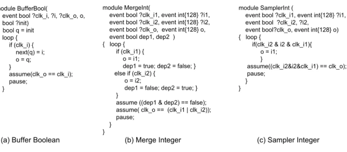
Since at each one of its instants, the signal zM_In has the value that M_In had at the previous instant, equation (a) expresses indeed that M_In is defined by In when a new

The Polychrony workbench implements a multi-clocked synchronous model of computation (the polychronous MoC [9]) to model control-intensive embedded software using the Signal

Figure 11 is a device example which has one output data port temperature output, in Signal it becomes a process with an output temperature, and this output is transfered to

Pour permettre le prototypage virtuel, la simulation et la validation formelle au plus tôt des architectures embarquées à base de composants, nous définissons une modélisation de