HAL Id: hal-00750604
https://hal.inria.fr/hal-00750604
Submitted on 11 Nov 2012
HAL is a multi-disciplinary open access
archive for the deposit and dissemination of
sci-entific research documents, whether they are
pub-lished or not. The documents may come from
teaching and research institutions in France or
abroad, or from public or private research centers.
L’archive ouverte pluridisciplinaire HAL, est
destinée au dépôt et à la diffusion de documents
scientifiques de niveau recherche, publiés ou non,
émanant des établissements d’enseignement et de
recherche français ou étrangers, des laboratoires
publics ou privés.
Texture-Less Planar Object Detection and Pose
Estimation Using Depth-Assisted Rectification of
Contours.
João Paulo Lima, Hideaki Uchiyama, Veronica Teichrieb, Eric Marchand
To cite this version:
João Paulo Lima, Hideaki Uchiyama, Veronica Teichrieb, Eric Marchand. Texture-Less Planar Object
Detection and Pose Estimation Using Depth-Assisted Rectification of Contours.. IEEE Int. Symp. on
Mixed and Augmented Reality, ISMAR’12, 2012, Atlanta, United States. pp.297-298. �hal-00750604�
Texture-Less Planar Object Detection and Pose Estimation
Using Depth-Assisted Rectification of Contours
João Paulo Lima*
Voxar Labs, CIn-UFPE, Brazil
Hideaki Uchiyama†
INRIA Rennes
Veronica Teichrieb*
Voxar Labs, CIn-UFPE, Brazil
Eric Marchand†
INRIA Rennes
ABSTRACT
This paper presents a method named Depth-Assisted Rectification of Contours (DARC) for detection and pose estimation of texture-less planar objects using RGB-D cameras. It consists in matching contours extracted from the current image to previously acquired template contours. In order to achieve invariance to rotation, scale and perspective distortions, a rectified representation of the contours is obtained using the available depth information. DARC requires only a single RGB-D image of the planar objects in order to estimate their pose, opposed to some existing approaches that need to capture a number of views of the target object. It also does not require to generate warped versions of the templates, which is commonly needed by existing object detection techniques. It is shown that the DARC method runs in real-time and its detection and pose estimation quality are suitable for augmented reality applications.
Keywords: Pose estimation, texture-less objects, augmented reality, RGB-D cameras.
Index Terms:! I.4.8 [Image Processing and Computer Vision]: Scene Analysis—Depth Cues, Range Data, Tracking; H.5.1 [Information Interfaces and Presentation]: Multimedia Information Systems—Artificial, Augmented, and Virtual Realities
1 INTRODUCTION
This paper proposes a technique for texture-less planar object detection and pose estimation using information provided by an RGB-D camera. Since the method makes use of depth data for obtaining a rectified representation of contours extracted from the RGB image, it is named Depth-Assisted Rectification of Contours (DARC). It shall be demonstrated that this normalized representation is invariant to rotation, scale and perspective distortions. It is obtained by transforming the contour points to a canonical view. Once the contours are rectified, they can be directly matched by computing their similarity using chamfer distance [1]. This allows finding correspondences between contours extracted from a query image and previously obtained rectified contours from a single template image of each object, without needing to compute perspective warps from the reference images. Based on these correspondences, accurate pose estimation and augmentation of texture-less planar objects in real-time is possible.
There are some object detection and pose estimation techniques suitable for non-textured objects that make use of depth data [5][6][7]. However, such methods need to capture several views of the target object, while the DARC technique needs only an RGB-D image of the planar object taken from a single view for
estimating its pose.
2 DEPTH-ASSISTED RECTIFICATION OF CONTOURS
First, contours are extracted from the query RGB image using the Canny edge detector [4]. Then, for each extracted contour, the 3D points that correspond to the 2D points of the contour and its inner contours are selected. In the remainder of this paper, the set of points that belong to a contour or its inner contours is named
contour group. Then, for each contour group, the corresponding 3D points !! of the 2D contour points !! are used to estimate the normal and orientation of the contour group via Principal Component Analysis (PCA). The centroid ! of the 3D contour points is computed, which is invariant to affine transforms. A covariance matrix is computed using !! and !, and its eigenvectors !!!! !!! !!! and corresponding eigenvalues !!!! !!! !!! are computed and ordered in ascending order. The normal vector to the contour group plane is !! [2]. If needed, !! is flipped to point towards the viewing direction. Contour group orientation is given by !! and !!, which can be seen as the ! and ! axis, respectively, of a local coordinate system with origin at ! [2]. There are four possible orientations given by combinations of the ! and ! axis with different signs. It only makes sense to consider all four orientations if mirrored or transparent objects might be detected. Otherwise, only two orientations are enough, which are given by using both flipped and non-flipped !! as the ! axis and computing the ! axis as the cross product of !! and !!.
In order to allow matching instances of the same contour group observed from different viewpoints, they are normalized to a common representation. Translation invariance is achieved by writing the coordinates of the 3D contour points !! relative to the centroid !. Rotation invariance is obtained by aligning !! and !! with the ! and ! global axes, respectively. Since the 3D contour points !! are in camera coordinates, they are scale invariant. Perspective invariance is obtained by aligning the inverse of the normal vector !! to the ! global axis. This way, the rectified contour points !!! can be computed as follows:
!!! ! !! !! !!!!!!! !!.
The rectified points should lie on the !" plane (! ! !). Since two or four orientations given by !! and !! are considered, each one is used to generate a different rectification of a contour group. All these rectifications are taken into account in the matching phase. In some cases the estimated orientation is not accurate. However, this is still sufficient for matching and pose estimation purposes.
After being rectified, query contour groups can be matched to a previously rectified template contour group. This is done by comparing each rectified query contour group with the rectified template contour group, considering the different orientations computed. First, a match is rejected if the upright bounding rectangles of the rectified contour groups do not have a similar size. Then, it is computed a coarse pose that maps the 3D unrectified template contour group to the 3D unrectified query contour group. Given the rotation !!
and translation !!
that rectify the template contour group and the rotation !! and translation !! * email: {jpsml, vt}@cin.ufpe.br
†
that rectify the query contour group, the coarse pose is obtained by: !! !! ! ! !! !! !! ! ! .
The 3D unrectified template contour group is transformed using the coarse pose ! ! and then projected onto the query image. After that, the upright bounding rectangle of the projected points is computed and compared with the upright bounding rectangle of the 2D query contour group. If they are not close to each other or their sizes are not similar, the match is discarded.
The similarity between template contour group projection and 2D query contour group is given by their chamfer distance [1]:
! !" !" ! !!! ! ! ! !!! ,
where ! is the number of points in the template contour group, !!! is the !-th template contour point and !"! is the query distance transform truncated to a value !. For each query contour group, the template contour group orientation with smallest chamfer distance is marked as a candidate match.
If there is a candidate match for a given query contour group, then a refined pose of the contour group is estimated from the previously computed coarse pose using the Levenberg-Marquardt algorithm. The query distance transform is used to compute the residuals. Finally, the chamfer distance between the template contour group and query contour group is calculated using the refined pose. If it is below a threshold, then the match is considered as correct.
In the current implementation, a single contour group is used for defining the pose of a given object. If the object contains several disjoint contour groups, one of these has to be selected for being used as template.
3 RESULTS
In order to evaluate DARC, some image sequences were captured using an RGB-D camera and synthetic RGB-D images were also generated. All the experiments were performed with 640x480 images. The hardware used in the evaluation was a Microsoft Kinect for Xbox 360 and a laptop with Intel Core i7 720QM @ 1.60GHz processor and 6GB RAM.
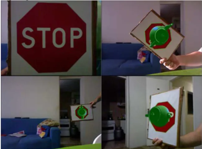
Figure 1 shows some results obtained with DARC for detection and pose estimation of different planar objects. It can be seen that DARC can deal with significant changes in rotation and scale as well as with perspective distortions. The contour groups used as templates are the octagon of the stop sign together with its inner contours, the continent frontier of the map and the outer square of the logo together with its inner contours.
Figure 1: Augmentation of a traffic sign (top left) under different poses using DARC.
Similarly to [6], the use of depth information allows DARC to distinguish objects that have the same shape but different sizes, as illustrated in Figure 2. The virtual objects are rendered with a different color and size depending on the size of the detected object. Detection methods that are based solely on RGB data are not able to differentiate, for example, between a small object at a close distance and a big object at a far distance when their projections have the same shape and size.
Figure 2: Distinction of objects with the same shape and different sizes using DARC. The bigger stop sign is augmented with a bigger green teapot, while the smaller stop sign is augmented with a smaller blue teapot.
The DARC method runs at ~20 fps while detecting a single template and then the frame rate declines linearly as the number of detected templates increases.
4 CONCLUSION
It was presented the DARC technique, which performs detection and pose estimation of texture-less planar objects by making use of depth data available in RGB-D consumer devices. DARC works in real-time and proved to be robust to in-plane and out-of-plane rotations, scale and perspective deformations, providing a pose with reasonable accuracy for AR applications.
Acknowledgements. This work is financially supported by the CAPES/INRIA/CONICYT STIC-AmSud project ARVS and by CNPq (process 141705/2010-8). Special thanks go to Mário Gonçalves, for lending a Kinect device.
REFERENCES
[1] H. Barrow, J. Tenembaum, R. Bolles, and H. Wolf. Parametric correspondence and chamfer matching: two new techniques for image matching. In IJCAI ’77, pages 659–663, Cambridge, Massachusetts, 1977.
[2] J. Berkmann and T. Caelli. Computation of surface geometry and segmentation using covariance techniques. In IEEE PAMI, volume 16, issue 11, pages 1114–1116, 1994.
[3] G. Borgefors. Distance transformations in digital images. In CVGIP, volume 34, issue 3, pages 344–371, 1986.
[4] J. Canny. A computational approach to edge detection. In IEEE
PAMI, volume 8, issue 6, pages 679–698, 1986.
[5] S. Hinterstoisser, C. Cagniart, S. Ilic, P. Sturm, N. Navab, P. Fua, and V. Lepetit. Gradient response maps for real-time detection of textureless objects. In IEEE PAMI, volume 34, issue 5, pages 876– 888, 2012.
[6] W. Lee, N. Park, and W. Woo. Depth-assisted real-time 3D object detection for augmented reality. In ICAT ’11, pages 126–132, Osaka, Japan, 2011.
[7] Y. Park, V. Lepetit, and W. Woo. Texture-less object tracking with online training using an RGB-D camera. In ISMAR ’11, pages 121– 126, Basel, Switzerland, 2011.