Conference Proceedings
EuroSun 2014
Aix-les-Bains (France), 16 – 19 September 2014Dynamic modeling and control strategy analysis of a micro-scale
CSP plant coupled with a thermocline system for power
generation
Rémi Dickes*, Adriano Desideri, Ian Bell, Sylvain Quoilin, Vincent Lemort
Thermodynamics Laboratory, Aerospace and Mechanical Engineering Department, Faculty of Applied Sciences University of Liège
Abstract
Concentrated solar power systems are characterized by strong transients and require proper control guidelines to operate efficiently. In this context, a dynamic model of a 5 kWe solar ORC system is developed in the Modelica language to investigate the possible advantages of coupling a concentrating solar power system with a thermocline packed-bed storage. The models of the solar field, the thermocline storage and the ORC unit are described and integrated in the open-source ThermoCycle library. A first regulation strategy is proposed and implemented into a controller unit. Results of a three-day simulation using real meteorological data are finally analyzed and discussed.
Key-words: Organic Rankine cycle, thermal energy storage, dynamic modeling
1. Introduction
In the last 30 years the power generation industry has been affected by a significant growth of small capacity intermittent renewable on-site power plants, promoting a progressive transition from a traditional centralized structure to an horizontal one (Resnick institute, 2012). In such a new envisaged distributed energy scenario, micro (3 – 20 kWe) and small (50 – 200 kWe) capacity concentrated solar power (CSP) plants can play a key role for remote power applications (Price, 2002). The relatively low cost of storing thermal energy represents one of the main advantages over PV technology (Peters, 2011). Among power generation technologies in the range of few kWe to few MWe, organic Rankine cycle (ORC) power units have been proven to be a reliable, mature and viable technology (Verneau, 1979) characterized by a simple system structure, easy maintenance and cost-effectiveness (Angelino, 1984). In the early 1980’s, a 150 kWe solar ORC system was built demonstrating the feasibility of the concept (Larson, 1983). Recent studies have investigated the potential of small capacity solar ORC systems highlighting the commercial potential for a power range from 100 kWe to 5 MWe (Price, 2002; Prabhu, 2005). Up to now, the only commercial solar ORC power system is the n-pentane 1 MWe Saguaro plant in Arizona, showing an overall efficiency of 12.1% (Canada et al., 2006). Progress has been recently presented in the micro power range. Kane et al. (2003) presented experimental data of a 13 kWe cascade hybrid ORC system based on scroll expander technology, using HFC-123 and HFC-134a as working fluid with a measured solar efficiency of 7.7 %. Within the framework of the Powersol project, a 5 kWe solar ORC unit using Solkatherm36 as working fluid was installed in 2009 in Almeria with an expected solar efficiency of 7% (Rodriguez et al., 2006). Different prototypes from 1 to 3 kWe solar ORC systems expanding HFC-245fa via a scroll expander have been installed by a cooperation between researchers at MIT, at the University of Liège and at the non-governmental organization STG International (Orosz et al., 2010; Quoilin et al., 2012). An experimental facility to test a 3 kWe ORC system for solar applications using HFC-245fa as working fluid and scroll machine as the expander technology has been recently designed (Georges et al., 2013) and built at the university of Liège under the Sun2Power project framework. The first presented experimental results show a maximum power output of 1.8 kWe with a measured expander isentropic efficiency of 68% (Dickes et al., 2014).
In this contribution, a dynamic model of a 5 kWe solar ORC system, based on the Sun2power concept, has been developed in the Modelica language (Elmqvist et al, 1997) to investigate the possible advantages of coupling the solar system with thermocline storage. Dynamic modeling tools have been recently used to assess the performance of small solar ORC systems under transient conditions. A Modelica model of a novel solar flash-ORC system working with complex molecules fluids coupled to direct thermal energy storage (TES) was presented by Casati et al. (2012). Ireland et al. (2014) developed a detailed Modelica model of the STG international solar ORC system to investigate the performance of different ORC control strategy over a four reference days. In this work, the presented dynamic model, based on the ThermoCycle library (Quoilin et al, 2014), is characterized by a simplified model of the ORC unit and focuses on assessing the possible thermodynamic advantage provided by the installation of an indirect thermocline storage system. A simulation over three reference days is performed and the results are used to analyze the benefits and drawbacks of the proposed control strategy.
2. System description
2.1 Overall system architecture
A schematic layout of the micro solar ORC system proposed in this contribution is shown in Figure 1. Among the available concentrated solar technologies, parabolic trough collectors are selected since they allow for a temperature range that fits the working conditions of the ORC power system. The presented concept features a two loop system with a packed-bed thermocline storage unit. The power unit integrated in the solar power plant is a 5 kWe non-recuperative Rankine cycle using HFC-245fa as working fluid (WF). Referring to the left side of Figure 1, the heat transfer fluid, Therminol 66, is pumped through the solar field where it gets heated up to the nominal temperature of °C. The fluid is then sent to the evaporator
(d) where thermal energy is transferred to the ORC power unit to produce electricity. At the evaporator outlet (e), the heat transfer fluid (HTF), at the nominal temperature of 140°C, is sent back to the solar field
(a) to be heated up again. However, because of the intermittent nature of solar irradiance (day/night, cloudiness), CSP plants are characterized by strong transients and mostly operate in off design conditions. To better match heat source availability to power generation requirement, a thermal energy storage (TES) tank is coupled to the system with an effective storage medium formed by the HTF and a packed-bed of solid filler, brick in this case. Following a predefined regulation strategy, thermal power is stored during excessively sunny periods to be later used during night or unfavorable meteorological conditions. A detailed description of the control variables and of the selected regulation strategy is reported in the next section. Furthermore, technical details and design data of the micro-CSP system are reported in Table 1.
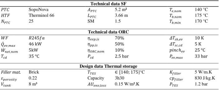
Tab. 1: Technical data of the micro-solar ORC system.
Technical data SF
SopoNova 5.2 m² 140 °C
Therminol 66 3.66 m 175 °C
25 SM 1.5 170 °C
Technical data ORC
70% 10 K
46 kW 50% 5 K
5kW 10% 25 °C
35 °C 2.5 bar 33 bar
Design data Thermal storage
Filler mat. Brick ]°C 5 W/m.K
0.22 Capacity 3h30 830 J/kg.K
Fig. 1: Schematic layout of the micro-solar ORC system coupled with the thermocline storage
2.2 Control parameters and strategy
As illustrated in Figure 1, three independent control variables can be operated to regulate the power plant:
The speed of the solar loop pump ( ) which controls the HTF mass flow rate circulating in
the solar collectors.
The speed of the power loop pump ( ) which controls the HTF mass flow rate circulating
in the evaporator of the power unit.
The heat power transferred to the ORC working fluid in the evaporator.
Although cannot be controlled directly in practice, it is assumed to have a perfect control on the ORC pump rotational speed in order to achieve the desired heat exchange rate in the evaporator. Furthermore, by adjusting the relative speed of the two pumps in the solar loop, the charge and discharge processes of the TES can be regulated. Indeed, three different scenarios can be recognized:
if : the same mass flow rate circulates in the solar loop and in the power loop, there is
not any HTF circulating through the TES. The stratified tank is neither charged nor discharged.
if : the HTF flow rate is higher in the solar loop than in the power loop. The
difference of mass flow rate enters the tank at the top and the TES is charged;
if : the HTF flow rate is smaller in the solar loop than in the power loop. The difference of mass flow rate enters the tank at the bottom and the TES is discharged.
Different control strategies can be conceived to operate such a system (Bayon et al, 2013). In this work, a first approach is investigated and its logic is illustrated in Figure 3. The three control variables are regulated to keep the temperature at the outlet of the solar field, , and at the outlet of the ORC evaporator, , as close as possible to their nominal values and . Indeed, thermocline TES systems take advantage
of the thermal stratification due to the density gradients which arise as a result of the temperature differences (Powell and Edgar, 2013). If a temperature inversion occurs, i.e. if the HTF enters at the top (bottom) of the TES with a colder (warmer) temperature than the temperature in the upper (lower) zone of the tank, the density gradient is inverted and buoyancy forces induce an undesirable mixing of the fluid within this zone. As depicted in Figure 2, this mixing process between the denser fluid layer and the layer below continues until equilibrium is reached to an intermediate temperature, resulting in a decrease of the TES exergy efficiency. Therefore, it is of primary importance to maintain a two-zone temperature profile inside the stratified tank even in case of fast transient conditions in the solar loop. This is achieved by providing a temperature at the TES ports ( and ) close to the nominal value.
Fig. 2: Temperature inversion in a thermocline system in case fluid at a temperature colder than Tb,nom enters at the top of the
TES, resulting in a degradation of the temperature profile.
Keeping the solar field outlet temperature close to is achieved by controlling the solar loop mass flow
rate via the pump speed . On the other hand, at the evaporator outlet is reached by adjusting
the heat transfer in function of the evaporator HTF supply conditions. The power loop pump speed
is regulated to control the charge and discharge of the TES, as shown in Figure 3. In case of excessively sunny periods, the thermal power collected by the solar field can be greater than the maximum
admissible thermal power of the ORC, . In this case, the mass flow of the power loop is
adjusted to transfer in the evaporator. As a consequence and the excess mass flow rate
enters the stratified tank at the top and the TES is charged.
In case of unfavorable solar conditions, the DNI can be too low and the minimum threshold is not
reached. If the TES is charged the power is extracted to adjust the temperature at the inlet of the evaporator, , close to . On the other hand, if the TES is not charged and the solar field outlet temperature is
lower than , the power loop mass flow rate is set equal to and the TES is neither charged nor
discharged.
3. Dynamic Modeling
In order to investigate the proposed control strategy under transient conditions, a dynamic modeling of the conceived system has been developed in the Modelica language (Elmqvist et at, 1997). The models used in the frame of this project are based on the open-source ThermoCycle library (Quoilin et al., 2014). This free-access library is dedicated to the modeling of thermal systems and has been under development at the University of Liège since 2009. Thermo-physical properties of the fluids are computed with the open-source CoolProp library (Bell et al., 2014), also developed at the University of Liège, and coupled to the ThermoCycle library through the CoolProp2Modelica package.
3.1. Solar field
Each parabolic trough collector is modeled by an absorber tube discretized in cells of constant volume
connected in series. This one dimensional (1D) discretization along the axial axis is justified by the large ratio between diameter and length of the heat collection element. The heat absorbed by the HTF in each cell, , is calculated by expressing the thermal energy balance i.e.
(Eq. 1)
(Eq. 2) (Eq. 3)
where is the solar energy reflected onto the ith cell of the absorber tube ( Eq. 2), and is the heat
loss related to the same cell (Eq. 3). is the surface area of one parabolic trough collector, DNI is the
solar direct normal irradiance, is the optical efficiency and is the cell axial length. is the linear heat
loss from the absorber and is given by Eq. 4:
(Eq. 4)
This correlation relates the heat loss to the HTF temperature, the ambient temperature, the wind speed and the solar irradiance. Further information concerning this correlation can be found in the open literature (Burkholder et al., 2009; Ireland et al. 2014).
3.2. Organic Rankine cycle system
The dynamics characterizing the ORC system are much faster compared to the ones characterizing the solar field and the thermocline tank. For these reasons, the ORC power block is a simplified quasi-steady state model which assumes constant performance parameters reported in Table 1. Such approach allows to decrease the computational time and the complexity of the whole CSP power plant system model and to focus the analysis on the dynamics concerning the solar field and the TES. In the ORC power block model, the evaporating pressure is computed as a function of the HTF temperature in order to keep a relatively constant pinch in the evaporator. The working fluid mass flow rate results as an output of the evaporator energy balance.
3.3 Thermocline Storage
The thermocline system is modeled by a 1D, finite volumes approach: the tank is supposed to be cylindrical and is discretized along its vertical axis in isothermal cells. The model is based on previous work
(Galli, 2011) and has been improved to account for a filler material in case of a packed bed storage system is used. Temperatures of the fluid and the filler material in a same cell are assumed equal (Bayon et al, 2013) and a constant pressure is prescribed in the whole tank. The model simulates the conductive heat transfer in the fluid, in the filler material and in the surrounding metal casing. It also accounts for the heat losses to the environment and for the flow reversal in case of charge and discharge processes. However, the turbulence mixing phenomenon due to the fluid introduction in the tank is neglected. Dynamics of the tank are evaluated by expressing the mass and energy balances in each finite volume cell. Because of the numerical diffusion
due to the finite volume modeling method (Powell et al., 2013; Casati et al., 2013), a high-enough number of nodes must be chosen (>30) to be able to model the thermocline effect occurring in the tank.
This model has been validated, both in charge and discharge mode, based on experimental data from the open literature (Zurigat et al., 1989; Pacheco et al., 2002).
3.4 Control unit
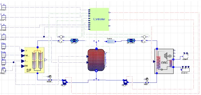
A control unit integrating the regulation strategy described in Section 2.2 is developed in the Modelica environment. Inputs to the controller are temperatures, pressures and mass flow rates measured in key locations of the system, as depicted in Figure 4. The solar loop pump ( ) is controlled by a single PI
controller aiming to match the target temperature at the solar field outlet. On the other hand, and are computed through an algorithm section implementing the cascade sequence depicted in Figure 3.
Fig. 4: Graphical user interface of the dynamic system model in Dymola
4. Results and Discussion
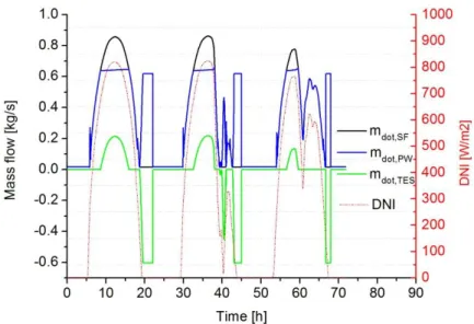
The dynamic model described in section 3 and controlled based on the scheme reported in section 2.2 is used to analyze the performance of the presented solar power plant over a three day reference scenario. The selected DNI data refers to Almeria in 1996, July 9th – 11th. Mass flow rates defined from the aforementioned control strategy are depicted in Figure 5. The solar loop flow rate, depicted in black, follows the DNI trend in order to keep the temperature at the solar field outlet as close as possible to its nominal value . For
high value of the DNI in the middle of the day, the maximum thermal power exchanged to the ORC evaporator, is reached and the power loop pump saturates. The mass flow in the power loop, ,
becomes smaller than the mass flow rate in the solar loop, as a consequence the TES mass flow rate,
reported in green, results positive and the tank starts to be charged. This scenario can be observed for each of the simulated days. At the end of each day or during unfavorable solar conditions (second day), the stratified tank is discharged in order to keep the temperature at the solar field outlet as close as possible to the minimum admissible temperature . This scenario can be identified in figure 5 by the fact that the TES
mass flow during tank discharge becomes negative.
Fig. 5: Mass flow rates in the solar loop (in black), in the power loop (in blue) and in the TES (in green)
Temperature profiles in key locations of the system are depicted in Figure 6. Oscillations of the temperature at the outlet of the solar field, in red, when the nominal value is reached, are the results of the PI control regulating the solar loop pump speed. As can be seen in Figure 6, at the end of each day decreases due to the decrease of the DNI, but the temperature at the inlet of the ORC evaporator , green line, is kept higher than the minimum value by discharging the TES system. In the same manner, during the second day discharging the TES system allows to dump the falling of DNI that causes a sharp fall of .
During working operation the temperature at the ORC outlet, in blue, is also kept close to its nominal value, , by adjusting the heat transfer through the ORC evaporator, .
Fig. 6: Temperature profiles of the solar field outlet (solid red line), the evaporator inlet (green line), the evaporator outlet (blue line)
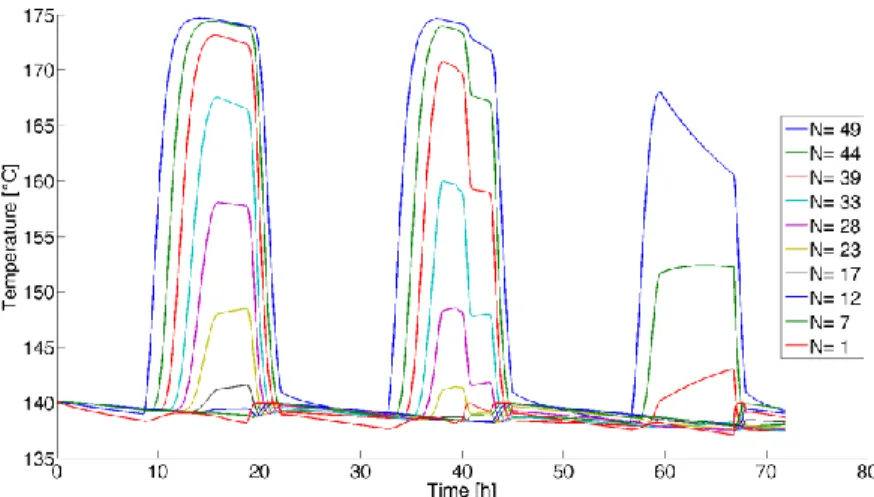
Temperature profiles at different levels of the TES tank are given in Figure 7. For each day a different charge load of the TES is achieved due to the variable solar condition. As can be observed the temperatures at the end of each day keep decreasing due to the heat losses and thermal diffusivity effects. As explained previously, the control strategy is developed in order to keep the temperatures at the tank ports close to the nominal values in order to avoid any degradation of the stratified temperature profile inside the TES. A dynamic representation of the temperature profile along the tank height is shown in Figure 8 and displays the temperature profile at a time that corresponds to the middle of the first day.
Fig. 7: Temperature profiles at ten vertically-equidistant heights of the TES tank
Fig. 8: Screenshot of the ThermoCycle Viewer display showing the temperature profile inside the TES tank at t = 5800 seconds Finally, thermal and mechanical powers involved in the system are reported in Figure 9. The regulation strategy is developed to keep the supplying temperature of the ORC evaporator as close as possible to a nominal value. When the solar irradiance declines, the solar loop mass flow rate is decreased in order to
keep close to its nominal value. Once reaches its minimum threshold the TES is discharged. Such
control strategy implies that the thermal power exchanged to the evaporator decreases close to zero at the end of the day and increases again during the TES discharging as can be seen at the end of each simulated day in figure 9. A better alternative would be to start discharging the TES as soon as the thermal power transferred to the evaporator decreases below a certain threshold. Both the influence of the temperature and the mass flow rate would be taken into account and a more constant thermal power through the ORC evaporator could be achieved, leading to a more constant power generation.
Fig. 9: Heat powers collected by the solar collectors (in cyan), transferred to the evaporator (in green), released in the condenser (in blue) and the net electrical output of the ORC (in magenta)
5. Conclusions and Future work
In this work, a dynamic model of a micro-solar ORC system is developed to investigate the possible advantages of coupling a CSP system with a thermocline packed-bed storage. First, the different models and the proposed control strategy are described. Then, simulation results over three typical summer days using real meteorological data are discussed and analyzed. Benefits of using a TES system with a preliminary control strategy to keep constant the temperatures at the outlet of the solar field and of the ORC evaporators are demonstrated. However, the proposed TES discharging strategy can be improved in order to better control the thermal power sent to the ORC evaporator. Furthermore, the modeling approach of the ORC unit should be improved to be more realistic. Finally, future works also include investigation of off-grid applications in which the net power generation of the ORC unit must meet a target non-constant profile.
6. Acknowledgment
The results presented in this paper have been obtained within the frame of the IWT SBO-110006 project The Next Generation Organic Rankine Cycles (www.orcnext.be), funded by the Institute for the Promotion and Innovation by Science and Technology in Flanders. This financial support is gratefully acknowledged.
Nomenclature
Acronyms Subscripts Symbols
CSP Concentrated Solar Power cd condenser A Surface area
DNI Direct Normal Irradiance ev evaporator ε Porosity
HTF Heat Transfer Fluid exp expander i Index
ORC Organic Rankine Cycle is isentropic L Length
PTC Parabolic Trough Collectors max maximum Mass flow
PW Power min minimum N Number
SF Solar Field nom nominal φ Heat loss
SM Solar Multiple opt optical Heat power
TES Thermal Energy Storage pp pump T temperature
WF Working Fluid sc sub-cooling V Speed/Volume
sh superheating Electrical power
References
Angelino, G., Gaia, M., Macchi, E., 1984. A review of Italian activity in the field of organic Rankine cycles. In: VDI Berichte – Proceedings of the International VDI Seminar. 539, 465–482.
Bayon, R., and Rojas, E., 2013. Simulation of thermocline storage for solar thermal power plants: from dimensionless results to prototypes and real-size tanks. International Journal of Heat and Mass Transfer. 60, 713-721.
Bell, I., Wronski, J., Quoilin, S., and Lemort, V., 2014. Pure- and Pseudo-Pure Fluid Thermophysical Property Evaluation and the Open-Source Thermophysical Property Library CoolProp. Industrial and Engineering Chemistry research. 53, 2498-2508.
Burkholder, F., Kutschner, C., 2009. Heat loss testing of Schott’s 2008 PTR70parabolic trough receiver. National Renewable Energy Laboratory. Technical Report.
Canada, S., Brosseau, D., and Price, H. 2006. Design and construction of the APS 1-MWE parabolic trough power plant. In Proceedings of the ASME International Solar Energy Conference.
Casati, E., Desideri, A., Casella, F., Colonna, P., 2012. Preliminary assessment of a novel small CSP plant based on linear collectors, ORC and direct thermal storage. In proceeding of SolarPACES 2012.
Casati, E., Galli, A., Colonna, P., 2013. Thermal energy storage for solar-powered organic Rankine cycle engines. Solar energy. 96, 205-219.
Dickes, R., Dumont, O., Declaye, S., Quoilin, S., Bell, I., Lemort, V., 2014. Experimental investigation of an ORC system for a micro-solar power plant. In proceeding of the 22nd international compressor engineering
conference at Purdue.
Elmqvist, H., Mattsson, S.E., 1997. Modelica – the next generation modeling language an international design effort. Proceedings of the 1st World congress on system simulation
Galli, A., 2001. Assessment of direct working fluid storage concepts for ORC power systems. PhD Thesis, Politecnico di Milano.
Georges, E., Declaye, S., Dumont, O., Quoilin, S., Lemort, V., 2013. Design of a small-scale organic Rankine cycle engine used in a solar power plant. International Journal of Low Carbon Technologies Advance.
Ireland,M.K., Orsoz.,M.S., Brisson,J.G., Desideri,A., Quoilin,S., 2014. Dynamic modeling and control system definition for a micro CSP plant coupled with thermal storage unit. Proceedings of ASME Turbo Expo 2014.
Kane, M., Larrain, D., Favrat, D., Allani, Y., 2003. Small hybrid solar power system. Energy. 28, 1427– 1443.
Larson, D. L., 1983. Final Report of the Coolidge Solar Irrigation Project. SAND83-7125. Albuquerque, New Mexico: Sandia National Laboratories.
Orosz, M.S., Quoilin, S., Hemond, H., 2010. SORC: A design tool for solar organic Rankine cycle systems in distributed generation applications. In: International Scientific Conference on Solar Heating, Cooling and Buildings.
Pacheco, J., Showlater, S., Kolb, W., 2002. Development of a molten-salt thermocline thermal storage system for parabolic trough plants. Journal of Solar Energy Engineering. 124, 153-159.
Peters, M., Schmidt, T., Wiederkehr, D., Schneider, M., 2011. Shedding light on solar technologies-a techno-economic assessment and its policy implications. Energy Policy. 39, 6422–6439.
Powell, K., Edgar, T., 2013. An adaptive-grid model for dynamic simulation of thermocline thermal energy storage system. Energy conversion and management, Vol 76, p.865-873.
Prabhu, E., 2006. Solar Trough Organic Rankine Electricity System (STORES) Stage 1: Power Plant Optimization and Economics.Technical Report NREL/SR-550-39433 National Renewable Energy Laboratory
Price, H., Hassani, V., 2002. Modular Trough Power Plant Cycle and System Analysis. Technical Report NREL/TP-550-31240 National Renewable Energy Laboratory.
Quoilin, S. Orosz, M., Hemond, H., Lemort,V., 2011. Performance and design optimization of a low-cost solar rankine cycle for remote power generation. Solar Energy. 85, 955-966.
Quoilin, S., Desideri,A.,Wronski,J.,Bell,I.,Lemort,V., 2014. Thermocycle: a Modelica library for the simulation of thermodynamic systems. Proceedings of the 10th international Modelica conference
Resnick Institute Report 2012. Grid 2020 Towards a policy of renewable and distributed energy resources California Institute of Technology
Rodriguez, L. G., Blanco-Galvez, J., 2006 Solar-heated Rankine cycles for water and electricity production: Powersol project. Desalination. 212, 311-318.
Verneau, A., 1979. Waste heat recovery by organic fluid Rankine cycle. In Proceedings from the First Industrial Energy Technology Conference Houston
Zurigat, Y., Lich, P., Ghajar, A., 1991. Influence of inlet geometry on mixing in thermocline thermal energy storage. International Journal of Heat and Mass Transfer. 34, 115-125.