HAL Id: hal-01166859
https://hal.archives-ouvertes.fr/hal-01166859
Submitted on 23 Jun 2015
HAL is a multi-disciplinary open access
archive for the deposit and dissemination of
sci-entific research documents, whether they are
pub-lished or not. The documents may come from
teaching and research institutions in France or
abroad, or from public or private research centers.
L’archive ouverte pluridisciplinaire HAL, est
destinée au dépôt et à la diffusion de documents
scientifiques de niveau recherche, publiés ou non,
émanant des établissements d’enseignement et de
recherche français ou étrangers, des laboratoires
publics ou privés.
A Dynamically Reconfigurable RF NoC for Many-Core
Alexandre Brière, Eren Unlu, Julien Denoulet, Andrea Pinna, Bertrand
Granado, Francois Pêcheux, Yves Louët, Christophe Moy
To cite this version:
Alexandre Brière, Eren Unlu, Julien Denoulet, Andrea Pinna, Bertrand Granado, et al.. A
Dynam-ically Reconfigurable RF NoC for Many-Core. ACM Great Lakes Symposium on VLSI, May 2015,
Pittsburgh, United States. pp.139-144, �10.1145/2742060.2742082�. �hal-01166859�
A Dynamically Reconfigurable RF NoC for Many-Core
Alexandre Brière
1, Eren Unlu
2, Julien Denoulet
1, Andrea Pinna
1,
Bertrand Granado
1, Francois Pêcheux
1, Yves Louët
2, Christophe Moy
21Sorbonne Universités, UPMC Univ Paris 06, UMR 7606, LIP6, F-75005 Paris, France
<firsname.lastname>@lip6.fr
2Supélec - IETR, F-35576 Cesson-Sevigne Cedex, France
<firsname.lastname>@supelec.fr
ABSTRACT
With the growing number of cores on chips, conventional electrical interconnects reach scalability limits, leading the way for alternatives like Radio Frequency (RF), optical and 3D. Due to the variability of applications, communication needs change over time and across regions of the chip. To address these issues, a dynamically reconfigurable Network on Chip (NoC) is proposed. It uses RF and Orthogonal Fre-quency Division Multiple Access (OFDMA) to create com-munication channels whose allocation allows dynamic recon-figuration. We describe the NoC architecture and the dis-tributed mechanism of dynamic allocation. We study the feasibility of the NoC based on state of the art components and analyze its performances. Static analysis shows that, for point to point communications, its latency is compara-ble with a 256-node electrical mesh and becomes lower for wider networks. A major feature of this architecture is its broadcast capacity. The RF NoC becomes faster with 32 nodes, achieving a ×3 speedup with 1024. Under realistic traffic models, its dynamic reconfigurability provides up to ×6 lower latency while ensuring fairness.
Categories and Subject Descriptors
C.1.2 [Processor Architectures]: Multiple Data Stream Architectures (Multiprocessors)—Interconnection architec-tures
Keywords
Many-Core; NoC; RF; Dynamic; Reconfigurable;
1.
INTRODUCTION
With the emergence of Chip Multi Processor (CMP), Net-work on Chip (NoC) have been introduced to make the dif-ferent processing elements soundly communicate together. First generation NoCs based on electrical interconnects have been studied in the past decade. Their bandwidth can be considered as infinite, but they show limitations in terms of Permission to make digital or hard copies of all or part of this work for personal or classroom use is granted without fee provided that copies are not made or distributed for profit or commercial advantage and that copies bear this notice and the full cita-tion on the first page. Copyrights for components of this work owned by others than ACM must be honored. Abstracting with credit is permitted. To copy otherwise, or re-publish, to post on servers or to redistribute to lists, requires prior specific permission and/or a fee. Request permissions from [email protected].
GLSVLSI’15,May 20–22, 2015, Pittsburgh, PA, USA. Copyright c 2015 ACM 978-1-4503-3474-7/15/05 ...$15.00. http://dx.doi.org/10.1145/2742060.2742082.
latency, when the number of cores increases. To overcome these limitations, alternatives such as 3D, optical and Ra-dio Frequency (RF) are now explored. In this paper, we present a RF NoC with dynamic allocation of communica-tion resources. It takes advantage of RF properties to op-timize bandwidth utilization and reduce latency. Section 2 presents an overview of related work. Section 3 describes the RF NoC architecture. Section 4 details the dynamic al-location algorithm. Section 5 presents experimental setups and results, and section 6 concludes the paper.
2.
RELATED WORK
2.1
Technology trends
Following recommendations of the ITRS [8], new tech-nologies are explored to overcome limitations of electrical connections. As chips integrate more and more components, distances, and therefore latency, increase. Pioneering con-tributions try to reduce distances with 3D [12, 15] or reduce traveling time with optic [13, 19] and RF [3, 2].
2.1.1
3D NoC
3D chips are based on stacked layers. In addition to planar connections, each layer has vertical connections with other layers. Some approaches mix 3D with optic [23] or RF [11] by using dedicated layers. 3D offers many advantages, but also adds significant thermal constraints.
2.1.2
Optical NoC
Optical is used to provide shortcuts for long distance com-munications. The use of optic, like other new technologies, not only allows a gain in bandwidth and latency, but also other architectural innovations such as new cache manage-ment policies [10]. A major drawback of optical NoC is the need of an external light source.
2.1.3
RF NoC
Similar to the optic solution, RF waves travels at a speed close to the speed of light. But, unlike optical solutions, RF directly benefits from full compatibility with CMOS technol-ogy. RF waves can be transmitted through a waveguide [2] or an antenna [4]. Solutions using antennas have greater flexibility, but they also increase consumption compared to waveguides, and suffer from lesser immunity to interference.
2.2
Communication Resources Allocation
As on-chip traffic is highly heterogeneous in the spatial and temporal domain, available bandwidth is generally
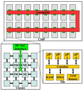
un-waveguide CMP Cluster μP 1 μP2 Grid Router μP 3 μP4 Crossbar RAM DMA Tile RF NoC Interface NE NW SE SW
Figure 1: CMP hierarchical RF NoC architecture derused and the design over-dimensioned in static intercon-nects. In optical or RF solutions, bandwidth is divided into dedicated channels that allow simultaneous transmissions. In a Single Write Multiple Read (SWMR) scheme, each com-munication channel is allocated to a specific node N so ev-ery other node can receive data sent by N [10]. In contrast, Multiple Write Single Read (MWSR) allocates each com-munication channels to a specific node N so it can receive information from other nodes [19]. MWSR has one draw-back: it requires an arbitration mechanism in the receiving devices to avoid collision, as multiple nodes may simultane-ously transmit data to the same destination node. SWMR supports broadcasting, while MWSR has to copy the broad-cast message to each dedicated channel nodes. In terms of energy, all nodes in a SWMR scheme listen to all commu-nication channels in the system (i.e. whole bandwidth). In that case, a node only requires small specific hardware for its pre-dedicated bandwidth. It is the opposite for MWSR: a node only has to listen to its pre-dedicated channel and just needs dedicated hardware to emit over the whole band-width. In Multiple Write Multiple Read (MWMR), each node can be assigned multiple channels to emit a message, and respectively each node can simultaneously receive data from different channels and nodes [21]. MWMR is the most energy consuming, as it requires arbitration for both emis-sion and reception. It is also by far the most flexible solution and allows more advanced reconfiguration mechanisms.
3.
PROPOSED CMP ARCHITECTURE
This section presents the architecture of the hierarchical RF NoC based CMP. As 3D adds significant thermal con-straints and optical needs an external light source, RF has been chosen. MWMR is chosen for its flexibility and broad-cast capacity. The propagation time in silicon is very short at the scale of a chip (about 0.5 ns for 100 mm), and can be considered almost constant for any source-destination com-bination. Moreover, the time needed to emit and receive a RF message is also constant. So, the RF NoC allows to transmit data in constant time, unlike router-based NoC, for which transmission duration varies linearly with the dis-tance between source and destination. However, this
dura-tion is still higher than a router-based NoC for short dis-tance communications. So RF must be used only when a certain distance threshold is reached, involving the use of a hierarchical architecture where the RF NoC is the top level communication medium.
3.1
CMP architecture
Figure 1 shows the global architecture of the CMP, with three levels of hierarchy: tiles, clusters and CMP. Each hier-archical level is associated with a specific interconnect: re-spectively wired crossbar, wired grid and RF global inter-connect. The tile is the lowest hierarchical level. It contains a local RAM, a DMA and processors, all connected to the crossbar. The local crossbar is connected to a grid router to access the second level (the wired grid) . A tile is connected by its router to the four nearest tiles, forming a cluster of M × M tiles. As the increase of the latency limits the size of a cluster, RF NoC is used as a third level interconnect when its latency becomes lower than the grid latency.
3.2
RF NoC architecture
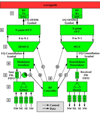
To allow inter cluster communications, each cluster in-cludes a RF NoC interface connected on one side to the four central tiles as illustrated in Figure 1, and on the other side to the waveguide. The RF NoC Interface, pictured in Figure 2, makes use of Orthogonal Frequency Division Mul-tiplexing (OFDM). In OFDM, the bandwidth is split into several orthogonal narrow band channels, providing high spectral efficiency, manageable equalization process and ro-bustness. The RF NoC use specifically a medium access scheme based on OFDM called Orthogonal Frequency Divi-sion Multiple Access (OFDMA). It adds the possibility for multiple senders to simultaneously use the same bandwidth while using only one transceiver per sender.
Data coming from routers of the four central tiles are stored into corresponding FIFOs 1. The arbiter 2 se-lects a packet from one of the FIFOs 1, converts it into specific RF NoC flow units (flits) and writes it in the FIFO
3 which possesses all the monitoring mechanisms to eval-uate the transmit requirements of the cluster. The flit is then serialized 4 into groups of bits according to the chosen modulation (BPSK, QPSK or 16-QAM), and finally creates the appropriate constellation symbol. The demux 5 par-allelizes the modulator output to feed the IFFT inputs 6, according to the channels/subcarriers allocated to the clus-ter. OFDM symbols generated by the IFFT 6 feeds the RF Tx and its DAC 7 and are sent to the waveguide. To trans-form OFDM in OFDMA, each cluster is allocated a certain number of subcarriers at every OFDM symbol to transmit its data and perform zero-padding to the rest of subcarriers. This way, the transmitter allows other nodes to send their data on the same OFDM symbol without interference. The choice of subcarriers is indicated by the RF Controller 7 to the demux 5 by the control signal
C. The other way to tune communication resources is to change the modulation. The choice of the modulation is also performed by the RF Controller according to its allocation algorithm presented in the next section and provided to the modulator by the control signal
B. Data reception follows the opposite path in all clusters. As each cluster decodes the entire OFDM symbol, data circulating on the RF NoC are visible by all clusters in the CMP. Thus, broadcast is an intrinsic feature of OFDMA. To perform the dynamic bandwidth allocation,
N-point IFFT RF Tx RFRx waveguide DAC ADC N-point FFT I/Q OFDM
Symbol I/Q OFDMSymbol
0 to N-1 0 to N-1
Modulator
Serializer DemodulatorDeserializer I/Q Constellation
Symbol I/Q ConstellationSymbol
Sent Flit FIFO Received Flit FIFO
Arbiter ControllerRF Router
NW NE SE SW NW NE SE SW DEMUX MUX Control Data B C D E A F 1 2 3 4 5 6 7 8
Figure 2: RF NoC Interface
the RF controller 7 evaluates the bandwidth requirements of its own cluster
A and the needs of other clusters
F.
4.
DYNAMIC BANDWIDTH ALGORITHM
To reach maximum bandwidth occupation, the OFDMA reconfigurability potential must be fully exploited. To do so, efficient algorithms based on instantaneous traffic demands are required to allocate subcarriers among clusters. The most significant metrics for these algorithms are latency and fairness. This issue is clearly linked to network theory and efficient solutions rely on state-of-the-art OFDMA sched-ulers, which optimize these metrics. Little’s Law states that to minimize average latency, a scheduler has to maximize the use of bandwidth. Among schedulers for conventional OFDMA networks, we choose Queue Proportional Scheduler (QPS) as the best guideline to design our allocation algo-rithm. QPS is a throughput optimal scheduler and is proven to provide fairness and small instantaneous latency [16]. The scheduler arbitrates N subcarriers to K nodes, proportion-ally to their instantaneous queue lengths and allows to allo-cate more subcarriers to nodes that communiallo-cate the most. A distributed bandwidth allocation scheme is used. In the block 3 of Figure 2, clusters compute their Queue State Information (QSI) and transmit them simultaneously with payload data to other clusters, thanks to OFDMA intrinsic broadcast feature. When each cluster has collected all other cluster’s QSI (
F in Figure 2), all RF Controller simultane-ously execute the bandwidth allocation algorithm. As each RF Controller processes identical data with the same algo-rithm, they all compute locally the same allocation solution, thus avoiding bandwidth conflict. Transmitting QSI simul-taneously with payload and using a distributed algorithm allow to avoid latency and extra communication overhead.
QSI is computed and transmitted every τ symbol, τ being a trade-off parameter. On the one hand, a small value of τ allows optimal allocation but the algorithm is executed more often and QSI transmission more frequent, consuming more bandwidth. On the other hand, larger values of τ result in
C-2 C-3 C-1 C-2 C-3 C-1 QS I C-2 C-3 C-1 C-2 C-3 C-1 C-2 C-3 C-1 QS I C-2 C-3 C-1 t-1 t t+1 t+τ-1 t+τ t+τ+1
Figure 3: EQPS algorithm with rotating QSI chan-nels on frequency and time
more available bandwidth, but outdated QSIs decrease the algorithm performance.
Expected Queue Proportional Scheduler (EQPS) algorithm is an extension of the original QPS algorithm. It provide the expected future QSI values of clusters. At first each cluster calculates its Deterministic Queue State Informa-tion (DQSI) which represents the minimum service demand. DQSI is the difference between the last received QSI and the bandwidth allocated during the last τ symbols. It is calculated using equation (1). With Qti, the QSI of
clus-ter i received on symbol t and Sit, the number of allocated
subcarriers from symbol t to symbol t + τ . Once DQSI is ob-tained, it is possible to take into account the incoming data to a cluster’s transmission queue during the next period of τ symbols. For this purpose, we use Exponentially Weighted Average Filter (EWMA). It estimates the next sample by weighting recent observation and previously computed aver-age using equation (2). With At
i, the amount of bits arrived
during the last τ symbols, and α, a scalar that weighs the effect of historical data compared to instantaneous sample, which is generally between 0.9 and 0.99 [22].
˙ Qt+τi = min(0, Q t i− S t i) (1) Aˆ t+τ i = (1−α)A t i+α ˆA t i (2)
Merging the average arrival, the last QSI value and the current bandwidth allocation, the RF Controllers use equa-tion (3) to calculate ˆQt
i, the estimated QSI for cluster i.
Then, using equation (4), they compute Sit+1, the allocated number of subcarriers to cluster i on symbol t + τ . With N , the number of subcarriers, and K the number of clus-ters. The result is rounded to the nearest larger integer to guarantee that every non-empty queue gets at least one sub-carrier resource, which ensures fairness. Note that, at the end of computation, the total number of allocated subcar-riers may exceed N . So extra subcarsubcar-riers are removed from the nodes with the higher values of St+1i .
ˆ Qti= ˙Q t i+ ˆA t i (3) S t+1 i = N Qˆ t i K P j=1 ˆ Qt j (4)
To avoid using the same subcarriers for QSI transmission every τ symbols, as it would constantly induce allocation penalties in some clusters, a rotating QSI channel is used during every allocation frame. It maps the QSI channels to different adjacent blocks of subcarriers, by moving the interval one by one. This procedure is illustrated in Figure 3.
5.
EXPERIMENTAL SETUP AND RESULT
In this section, we assume a realistic bandwidth of 20 GHz for RF and a CMP with 32 clusters and 4 cores per tile.
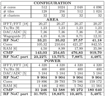
CONFIGURATION # cores 512 1024 2 048 4 096 # tiles 128 256 512 1 024 # clusters 32 32 32 32 AREA IFFT/FFT [18] 20,27 20,27 20,27 20,27 Tx/Rx [9] 1,23 1,23 1,23 1,23 DAC/ADC [5] 7,36 7,36 7,36 7,36 Wageguide [7] 4,35 6,16 8,71 12,31 RF NoC 33,21 35,02 37,57 41,18 Cores 105,32 210,64 421,27 842,55 RAM [6] 4,50 8,99 17,99 35,98 CMP 143,03 254,65 476,83 919,70 RF NoC part 23,22% 13,75% 7,88% 4,48% POWER IFFT/FFT [18] 4 320 4 320 4 320 4 320 Tx/Rx [9] 400 400 400 400 DAC/ADC [5] 5 184 5 184 5 184 5 184 RF NoC 9 904 9 904 9 904 9 904 Cores 19 896 39 793 79 586 159 172 RAM [6] 1 446 2 891 5 782 11 564 CMP 31 246 52 588 95 272 180 640 RF NoC part 31.70% 18,83% 10,40% 5,48%
Table 1: Chip area (mm2) and power (mW)
5.1
Surface and power estimation
In order to evaluate the feasibility of a CMP using our RF NoC, we perform a basic estimation of surface and power. We compare these characteristics with those of an existing CMP, the Intel Core i7-5960X.
5.1.1
Experimental setup
Surface and power are calculated on the basis of state of the art components, assuming a 22 nm target technol-ogy as used for the i7-5960X. For digital components, equa-tion (5) is used to get SN, the normalized surface in the
target technology N , depending on the surface SQ in the
original technology Q. According to ITRS [8], when the size of transistors decreases by a 0.7 factor, the power consump-tion decreases by a 0.65 factor. Equation (6) gives WN,
the normalized power consumption in technology N , based on the power consumption WQin the original technology Q.
The scaling of analog components is not as simple, since it is necessary to take into account other factors. So we directly used the surface and power of state of the art components.
SN= SQ× (N/Q)2 (5) WN = WQ× 0.65log0.7(N/Q) (6)
5.1.2
Result
Table 1 presents surface and power of the components, showing that the RF NoC area is mainly due to FFT/IFFT, ADC/DAC and the waveguide. The rest of the surface is mainly occupied by cores and their caches (ARM Cortex-A5). Compared to the i7-5960X, whose surface is 355 mm2,
the first three cases have a realistic area. The last one seems less realistic with current technology but should be achievable in the future. Power consumption and surface do not vary in the same way. This is due to the increasing length of the waveguide. The surface calculation uses the true length of the waveguide whereas the power calculation uses the average length of the different cases. Table 1 shows that the power consumption of the RF NoC is mainly due to FFT/IFFT and ADC/DAC. Compared to the i7-5960X, whose power consumption is 140 W, all cases are realistic, demonstrating the feasibility of the RF NoC from this point of view. The part of the RF NoC in the global surface and
16 32 64 128 256 512 1 024 0 20 40 60 80 100 120 140 160 180 200 Grid (p2p) RF-NoC (p2p) Grid (broadcast) RF-NoC (broadcast) Number of tiles D el ay ( n s)
Figure 4: Average latency for P2P flit transfer power decreases as the number of cores increase, making the RF NoC more and more interesting.
5.2
Intrinsic characteristic evaluation
5.2.1
Experimental setup
The RF NoC is compared with a router based electrical NoC using analytical models. Performance are evaluated in the case of a random traffic without contention. We as-sume cores running at 1 GHz and a bandwidth divided into 512 subcarriers. A grid router has a latency lRG of 3
cy-cles, one for reading data, one for selecting the output port and one for writing data to the chosen port. Equation (7) gives DCM P, the average number of crossed routers to go
from one tile to another, including the original tile router. We considered a CMP with a grid of N × N tiles. We get Lgrid the average latency of a grid with equation (8).
DCM P =
2
3N + 1 (7) Lgrid= DCM P × lRG (8) The latency of the RF NoC lRF is 25 cycles, which
corre-sponds to the OFDM symbol duration. We also take into account the average number of cycles to go from source to the transmitting RF NoC Interface and from the receiving RF NoC Interface to destination. For a CMP containing clusters of M × M tiles, the average distance Dcluster
be-tween tiles and RF router is given by equation (9) if M is even, and equation (10) if M is odd. Equation (11) gives LN oC RF the average latency of the RF NoC.
Dcluster= M 2 (9) Dcluster= M2+ 2M − 1 2M (10) LN oC RF = lRG× Dcluster+ lRF (11)
We can compare the average duration of a flit reception with the RF NoC and with a grid connecting all the tiles of the CMP. We set the number of clusters to 32 and we modify the size of CMP by varying the number of tiles per cluster.
5.2.2
Result
Access to the RF NoC is shared by the four central tiles in the first case, whereas it is in the single central tile in the second case. This different location of the RF router explains the staircase shape of the RF NoC latency curves shown in Figure 4. For point-to-point (P2P) communications, the RF NoC becomes faster for CMPs of at least 512 tiles.
To perform a broadcast, data must cross a maximum of 2N − 1 routers for a grid and a maximum of 2M routers plus the waveguide for the RF NoC, where N is the CMP
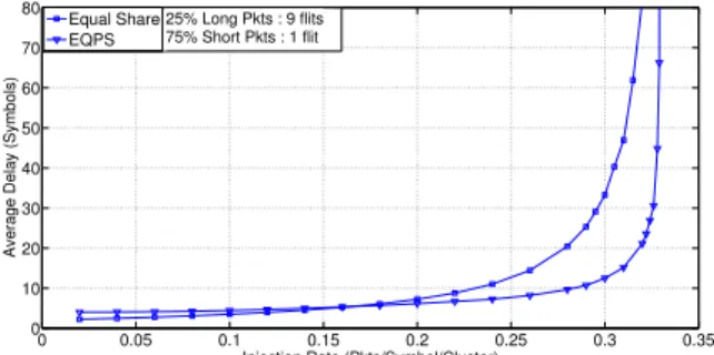
0 0.05 0.1 0.15 0.2 0.25 0.3 0.35 0 10 20 30 40 50 60 70 80
Injection Rate (Pkts/Symbol/Cluster)
Average Delay (Symbols)
Equal Share EQPS
25% Long Pkts : 9 flits 75% Short Pkts : 1 flit
Figure 5: Average latency under Poisson traffic width while M is the cluster width. Figure 4 shows that the RF NoC is faster for CMPs of at least 32 tiles.
5.3
Evaluation of dynamic allocation
5.3.1
Experimental setup
Note that in this experiment, QPSK is the only used mod-ulation order. Based on experiments, we decide to compute QSI every 8 symbols. It provides the necessary amount of computation time for the RF Controller to perform subcar-riers allocation while only 3.125% of bandwidth is used for QSI transmission. Assuming that the shortest packet is one flit, incoming packets are split into 64 bits flits. We divide the 1024 subcarriers into 256 groups of 4 subcarriers modu-lated with QPSK during 8 symbols, thus providing 64 bits of service during every allocation frame and ensuring that each non-idle node gets a chance to transmit at least one flit. QSI values are 8-bit long, representing a queue of 0 to 255 of awaiting flits. That way, we only need 4 subcarriers to modulate a cluster’s QSI on one symbol. So, we use 128 subcarriers during one symbol to transmit all the QSIs.
Messages are either small packets (read requests, acknowl-edgements, etc.), or long packets (write requests, read re-sponses followed by cache lines). According to [14], we set the proportion of short packets (1 flit - 64 bits) and long packets (9 flits - 576 bits) to 75% and 25%. It is assumed that cache lines are 64 bytes, thus cache coherence packets contain 8 payload flits and 1 overhead flit, featuring all nec-essary informations (destination, ID, etc.). When a packet is generated, a Bernoulli process determines its length.
We use OMNET++ to test the bandwidth allocation pro-tocol. We focus on inter-cluster communications as we aim to show the benefits of the dynamic allocation algorithm. Thus, we discard intra-cluster communications. We also as-sume infinite capacity transmit queues. With state-of-the-art on-chip simulators, generating memory traffic by using benchmark applications is not efficient for more than 1000 cores [10]. So we use synthetic models to mimic memory traffic as a first approach.
5.3.2
Results - Uniform On-Chip Traffic
One of the most widely used traffic models for on-chip net-works is the uniform model, where each node may generate a packet every cycle with a probability p. However, as we have 64 cores per cluster and multiple cycles in an OFDM symbol (with 1 GHz processors, one symbol corresponds to 50 cy-cles), there may be multiple packets generated in a symbol. As aggregation of multiple independent Bernouilli processes is a Poisson process, we model the number of packets gener-ated in a cluster on each symbol as a Poisson distribution. We compare the dynamic allocation (EQPS) with the case
0 20 40 60 80 100 120 140 160 10−6 10−5 10−4 10−3 10−2 10−1 100
Delay Bound − D0 (symbols)
P(D>D 0 ) EQPS Equal Share H = 0.7
Total Injection = 1 packet/symbol 25% Long Packet / 75% Short Packet
Figure 6: ICDF under realistic traffic model where subcarriers are statically and equally allocated (Equal Share). Figure 5 shows the packets average latency under Poisson traffic with increasing injection rate. Note that, for injection rates smaller than 0.15 packets/symbol/cluster, Equal Share performs better than EQPS. Indeed, EQPS re-arbitrates subcarriers every 8 symbols, based on the instan-taneous QSI and a moving average, which does not provide high efficiency when queue length values are small. As traf-fic load increases and instantaneous queue lengths get big-ger and bigbig-ger, the need to reallocate bandwidth arises and EQPS becomes more efficient, pushing back the saturation threshold of the network.
5.3.3
Results - Realistic On-Chip Traffic
Uniform and Markovian traffic do not accurately capture the features of on-chip traffic. So, new synthetic models have been developed. The fractal and self-similar behavior of CMP memory traffic both in time and space have been observed [1]. One characteristic of memory traffic of shared memory CMP is the long-range dependence (LRD) [17]. LRD reflects the temporal similarity of the traffic generation pro-cess in different scales of time intervals. It can be modeled by a power-law decaying covariance function : γ(k) = ck−α, where c is an arbitrary scalar and α is an exponent reflecting the degree of long-range dependence. One method to char-acterize and generate stochastic long-range dependent traffic is to use Hurst Parameter, H, where H = (2 − α)/2 [20]. A synthetic traffic model for cache-coherent CMPs, which at-tains an 95% accuracy compared to real application traces has been proposed [17]. We choose this model to test the RF NoC and EQPS algorithm under realistic on-chip traf-fic conditions, with H = 0.7 (an approximate mean for all kind of applications). To generate traffic with Hurst param-eter in OMNET++, we use the method explained in [20], where the number of generated packets by a node at any instance is determined by the aggregation of many Pareto distributed ON-OFF processes (we set this number to 500, which is fairly sufficient for each cluster). Similarly, clusters injection rates are assumed to be Gaussian distribution.
We tested our algorithm under non-uniform traffic and plotted the Inverse Cumulative Probability Density Func-tion (ICDF), the probability that the latency of a packet is larger than a delay bound, P (D > D 0). Figure 6 shows ICDF for EQPS and Equal Share, with an injection rate of 1 flit/symbol/cluster. It shows a ×6 improvement, showing the benefits of the EQPS algorithm.
6.
CONCLUSION
Current RF and optical NoC create multiple channels re-quiring several transceivers per cluster, which limit variety
and granularity of reconfiguration schemes. We propose in this paper a dynamically reconfigurable RF NoC based on OFDMA. We describe the hierarchical architecture of the CMP using the RF NoC and propose a dynamic bandwidth allocation algorithm. Static analysis shows that RF NoC av-erage latency is comparable with mesh avav-erage latency for P2P communications but up to ×3 lower for broadcast. Un-der realistic traffic models, the dynamic bandwidth alloca-tion algorithm provides up to ×6 lower latency than static schemes. To comfort those promising results, a SystemC model of the architecture is under development so future work can evaluate more precisely performances with bench-marks. Moreover, one can imagine new cache coherency protocols taking advantage of the low cost broadcast of the proposed RF NoC.
7.
ACKNOWLEDGMENTS
This work has been supported by the French National Research Agency under grant ANR-12-INSE-0004.
8.
REFERENCES
[1] P. Bogdan and R. Marculescu. Statistical physics approaches for network-on-chip traffic
characterization. In IEEE/ACM International Conf on Hardware/Software Codesign, pages 461–470, 2009. [2] M. Chang, J. Cong, A. Kaplan, M. Naik, G. Reinman, E. Socher, and S. Tam. Cmp network-on-chip overlaid with multi-band rf-interconnect. In High Performance Computer Architecture (HPCA), IEEE International Symposium on, pages 191–202, 2008.
[3] M. Chang, V. P. Roychowdhury, L. Zhang, H. Shin, and Y. Qian. Rf/wireless interconnect for inter-and intra-chip communications. Proceedings of the IEEE, 89(4):456–466, 2001.
[4] S. Deb, K. Chang, M. Cosic, A. Ganguly, P. Pande, D. Heo, and B. Belzer. Cmos compatible many-core noc architectures with multi-channel millimeter-wave wireless links. In Great Lakes Symposium on VLSI (GLSVLSI), pages 165–170. ACM, 2012.
[5] Y. Duan and E. Alon. A 12.8 gs/s time-interleaved adc with 25 ghz effective resolution bandwidth and 4.6 enob. Solid-State Circuits, IEEE Journal of,
49(8):1725–1738, 2014.
[6] C.-S. Gong, C.-T. Hong, K.-W. Yao, and M.-T. Shiue. A low-power area-efficient sram with enhanced read stability in 0.18-µm cmos. In Circuits and Systems, APCCAS 2008, IEEE Asia Pacific Conference on, pages 729–732, 2008.
[7] J. Hu, J. Xu, M. Huang, and H. Wu. A 25-gbps 8-ps/mm transmission line based interconnect for on-chip communications in multi-core chips. In IEEE MTT-S International Microwave Symposium Digest (IMS), pages 1–4, 2013.
[8] ITRS. International technology roadmap for semiconductors report, 2013 version. [9] K. Jongsun, B. Gyungsu, and M. Chang. A
low-overhead and low-power rf transceiver for short-distance on-and off-chip interconnects. IEICE Transactions on Electronics, 94(5):854–857, 2011. [10] G. Kurian, J. Miller, J. Psota, J. Eastep, J. Liu,
J. Michel, L. Kimerling, and A. Agarwal. Atac: A
1000-core cache-coherent processor with on-chip optical network. In International Conference on Parallel Architectures and Compilation Techniques, pages 477–488. ACM, 2010.
[11] J. Lee, M. Zhu, K. Choi, J. H. Ahn, and R. Sharma. 3d network-on-chip with wireless links through inductive coupling. In International SoC Design Conference (ISOCC), pages 353–356. IEEE, 2011. [12] F. Li, C. Nicopoulos, T. Richardson, Y. Xie,
V. Narayanan, and M. Kandemir. Design and management of 3d chip multiprocessors using network-in-memory. ACM SIGARCH Computer Architecture News, 34(2):130–141, 2006. [13] I. O’Connor. Optical solutions for system-level
interconnect. In International Workshop on System level Interconnect Prediction, pages 79–88. ACM, 2004. [14] Y. Pan, J. Kim, and G. Memik. Tuning nanophotonic
on-chip network designs for improving memory trafics. In PICA@ MICRO2009.
[15] V. Pavlidis and E. Friedman. 3-d topologies for networks-on-chip. Very Large Scale Integration (VLSI) Systems, IEEE Trans. on, 15(10):1081–1090, 2007. [16] K. Seong, R. Narasimhan, and J. M. Cioffi. Queue
proportional scheduling in gaussian broadcast channels. In IEEE International Conference on Communications (ICC), pages 1647–1652, 2006. [17] V. Soteriou, H. Wang, and L.-S. Peh. A statistical
traffic model for on-chip interconnection networks. In IEEE International Symposium on Modeling, Analysis, and Simulation of Computer and Telecommunication Systems (MASCOTS), pages 104–116, 2006.
[18] S.-N. Tang, J.-W. Tsai, and T.-Y. Chang. A 2.4-gs/s fft processor for ofdm-based wpan applications. Circuits and Systems II: Express Briefs, IEEE Transactions on, 57(6):451–455, 2010.
[19] D. Vantrease, R. Schreiber, M. Monchiero,
M. McLaren, N. P. Jouppi, M. Fiorentino, A. Davis, N. Binkert, R. G. Beausoleil, and J. H. Ahn. Corona: System implications of emerging nanophotonic technology. ACM SIGARCH Computer Architecture News, 36(3):153–164, 2008.
[20] W. Willinger, M. S. Taqqu, R. Sherman, and D. V. Wilson. Self-similarity through high-variability: statistical analysis of ethernet lan traffic at the source level. Networking, IEEE/ACM Transactions on, 5(1):71–86, 1997.
[21] C. Xiao, F. Chang, J. Cong, M. Gill, Z. Huang, C. Liu, G. Reinman, and H. Wu. Stream arbitration: Towards efficient bandwidth utilization for emerging on-chip interconnects. ACM Transactions on Architecture and Code Optimization (TACO), 9(4):60, 2013.
[22] Q. Xu, D.-n. Cheng, and Y.-d. Fu. Traffic feature distribution analysis based on exponentially weighted moving average. In Computer Science and Automation Engineering (CSAE), IEEE International Conference on, volume 1, pages 535–539, 2012.
[23] Y. Ye, L. Duan, J. Xu, J. Ouyang, M. Hung, and Y. Xie. 3d optical networks-on-chip (noc) for
multiprocessor systems-on-chip (mpsoc). In 3D System Integration (3DIC), IEEE International Conference on, pages 1–6, 2009.