HAL Id: hal-00585362
https://hal.archives-ouvertes.fr/hal-00585362
Submitted on 1 Jun 2015
HAL is a multi-disciplinary open access
archive for the deposit and dissemination of
sci-entific research documents, whether they are
pub-lished or not. The documents may come from
teaching and research institutions in France or
abroad, or from public or private research centers.
L’archive ouverte pluridisciplinaire HAL, est
destinée au dépôt et à la diffusion de documents
scientifiques de niveau recherche, publiés ou non,
émanant des établissements d’enseignement et de
recherche français ou étrangers, des laboratoires
publics ou privés.
Influence of the sample structure on the corona type
poling efficiency of guest-host electro-optic polymers
Kenny Philippe Auguste, Hind Mahé, Abdel Karim Ferchichi, Hong Wu Li,
Jean-Pierre Vilcot
To cite this version:
Kenny Philippe Auguste, Hind Mahé, Abdel Karim Ferchichi, Hong Wu Li, Jean-Pierre Vilcot.
Influ-ence of the sample structure on the corona type poling efficiency of guest-host electro-optic polymers.
18th Telecommunications Forum (TELFOR 2010), Nov 2010, Belgrade, Serbia. pp.775-778.
�hal-00585362�
Abstract — During the last decades, the research for the development of optical devices based on polymers is very extensive. Those organic materials make possible low manufacturing cost and high performance microwave photonic devices, such as optical modulators, with very large bandwidth and low drive voltage at 1310 nm and 1550 nm. To generate and maximize the electro-optic effect in those materials, it is necessary to orient all the chromophore dipoles in the same direction. In this paper, wire-to-plane configuration for corona poling and in-situ second harmonic generation detection techniques are used respectively to induce and to detect the alignment of the chromophores in a guest-host system (APC-CPO1). We report on experimental results obtained for various sample structures under same poling conditions. The sample structure affects the intensity of the corona current and its influence on poling efficiency has been studied through in-situ measurement of SHG (Second Harmonic Generation).
Keywords — Corona poling, electro-optic polymer, in-situ SHG.
I. INTRODUCTION
he growing demand for large bandwidth and low manufacturing costs light modulation devices make electro-optic (EO) polymers promising candidates to lithium niobate replacement these last decades [1]-[2]. Those materials are mostly used for ring resonators [3], directional couplers [4] and Mach-Zehnder interferometers (MZI) [5]-[7]. EO devices such as MZI present very promising characteristics such as low drive voltage [8] and
Authors would like to thank the ANR (French National Research Agency) for their financial support through the project “MODPOL”. K. R. Philippe Auguste is with Institut de Recherche en Electrotechnique et Electronique de Nantes Atlantique, Université de Nantes, 2, rue de la Houssinière, BP 92208, 44322 Nantes Cedex – France. (Email: Kenny-Robert.Philippe-Auguste@univ-nantes.fr).
H. Mahé is with Université européenne de Bretagne, laboratoire Foton, UMR 6082, CCLO, ENSSAT, BP 80518, 22305 Lannion cedex – France (Email: hind.mahe@enssat.fr).
K. Ferchichi is with Institut de Recherche en Electrotechnique et Electronique de Nantes Atlantique, Université de Nantes, 2, rue de la Houssinière, BP 92208, 44322 Nantes Cedex – France. (Email:
Karim.Ferchichi@univ-nantes.fr).
H. W. Li is with Institut de Recherche en Electrotechnique et Electronique de Nantes Atlantique, Université de Nantes, 2, rue de la Houssinière, BP 92208, 44322 Nantes Cedex – France. (Email:Hongwu.Li@univ-nantes.fr)
J.-P. Vilcot is with Institut d’Electronique, de Microélectronique et de Nanotechnologie, Avenue Poincaré, BP 60069, 59652 Villeneuve d’Ascq Cedex – France. (Email: jean-pierre.vilcot@iemn.univ-lille1.fr).
high bandwidth [9].
EO polymers are constituted of a polymer matrix in which nonlinear optical (NLO) chromophores (dyes) are dispersed. NLO chromophores are randomly oriented in natural state, so without preferential orientation no macroscopic EO effect is displayed. In order to activate the EO effect in chromophores-doped polymers, it is then necessary to create a noncentrosymmetry. An alignment, as complete as possible, of the NLO dyes of the material is necessary to generate the macroscopic nonlinear properties in the polymers. This orientation can be created by means of light-assisted poling technique [10] or thermal poling techniques. The thermal poling techniques that are commonly used are the corona poling [11] and the parallel plate electrode poling [12]. For the thermal poling techniques, the material is heated close to the glass transition temperature (Tg) of the polymer in order to
increase the mobility of the NLO species in this matrix. As this temperature is near the Tg of the system, an electric
field is applied to align all the NLO species in the same direction.
II. EXPERIMENTAL SETUP AND CONDITIONS
A. Experimental setup
Fig. 1 – Experimental bench for in-situ SHG detection during corona poling process
The corona effect is a discharge process involving usually two asymmetric electrodes: one highly curved (such as the tip of a needle or a small diameter wire) and one of low curvature (such as a plate or the ground). The high curvature ensures a high potential gradient around the electrode, so the surrounding neutral fluid, usually air, is ionized, ions are created around the electrode and deposited on the sample surface, generating a strong
Influence of the sample structure on the corona
type poling efficiency of guest-host
electro-optic polymers
Kenny Robert Philippe Auguste, Hind Mahé, Abdel Karim Ferchichi, Hong Wu Li, Jean-Pierre Vilcot
electric field in the sample and resulting in an alignment of chromophores dipoles. The second harmonic generation (SHG) is detected as an indicator of the chromophores alignment.
The experimental bench used for in-situ SHG detection while corona poling is shown on the Fig. 1. The wire-to-plane configuration is chosen to expand the area of the poling process to cover the maximum surface of a full 3” wafer. There are 4 wires, spaced 1 cm from each other and they have a length of 12.5 cm. The distance between the ground plane and the tungsten wires is 6 mm. The diameter of the tungsten wire is 125 µm. The maximal voltage which can be delivered is 12.5 kV. For monitoring the poling on the same setup it is possible to acquire the SHG signal in-situ so in real time by a reflection type setup owing to the reflectivity of the silicon wafer on which the polymer films are deposited. The pulsed laser source is placed in an axis normal to that of a photomultiplier (PM). Its pulse duration is smaller than 2 ns and the power delivered is 9 µJ per pulse. Both the polarization of the laser light beam and that of the SHG signal on the PM active surface are parallel to the incident plane. The laser is operating at fundamental wavelength of 1064 nm. So the wavelength of the second harmonic signal is 532 nm. To avoid saturating the PM by the fundamental signal (much more intense than the second harmonic signal), an optical band pass filter centered on 532 nm is placed in front of the PM (Fig. 1).
In order to obtain the power density required for the second harmonic generation on the sample, a convex lens is placed before the sample, so the beam-waist of the input lightwave of 250-µm radius is focalized on the sample. The fundamental laser beam impacts the sample with an incidence angle of 45°.
The amplitude of the electrical signal corresponding to the SHG signal is measured by a digital oscilloscope; each measurement data point results from an averaging over 9 pulses to overcome the laser intensity fluctuation. In order to detect very low SHG signal, all the experiments are carried out in a dark environment because the PM is very sensitive and could be damaged by room light.
B. Samples
The samples used for the experiments are realized on 3” silicon wafers. The EO polymer is a guest-host system. The NLO dye is the chromophores CPO1 [13]. The matrix polymer is amorphous polycarbonate (APC). The glass transition temperature of the system is 150°C and its refractive index is 1.61. OG-125 polymer is used for both upper and lower cladding layers when these later are used. It is UV-cured to improve its thermal resistance (Tg of
55°C and after UV-curing, it can resist to temperatures up to 200°C) and its refractive index is 1.48. The temperature for the poling is fixed to 420 K (147°C).
The samples are made by spin-coating. The thickness is respectively 3.5 µm for each claddings layer (when used) and 3.4 µm for the EO polymer film. The samples are fabricated using different structures: without claddings (only EO polymer film), with only bottom cladding and
with both bottom and top claddings. The same samples have been fabricated incorporating a gold film which is deposited on the wafer before the spin-coating of the polymers films (so directly on the silicon substrate).
C. Thermal cycle and poling voltage
To determine the poling voltage, the sample, made of only the EO polymer film deposited on the silicon wafer, is slowly heated (5°C/mn ramp) to the poling temperature. It takes around 25 mns to rise from room temperature to 147°C (the chosen poling temperature). While this temperature is held for 30 mns, the voltage is slowly raised (0.1 kV/mn ramp) until the appearance of a corona current. This current appears shortly before the beginning of the SHG signal. The poling voltage of 6.8 kV is determined by this method. This voltage is applied for the poling of all the other samples mentioned in the previous section. For the poling of these samples, the temperature rise is the same as described above, the temperature plateau duration has been reduced to 20 mns instead of 30 mns and the sample is cooled down to room temperature by natural cooling. The 6.8 kV is applied to the sample from the beginning of the temperature rise till the return to room temperature. The complete process takes about 90 mns.
III. RESULTS AND DISCUSSION
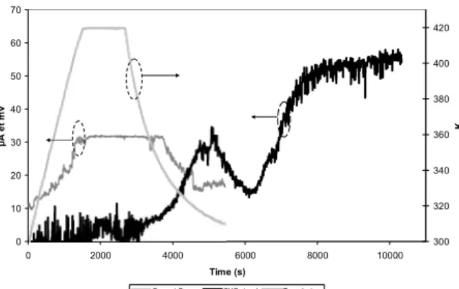
As mentioned in section II, the corona current is the precursor sign announcing a sufficiently high electrical field to align the NLO species (as can be seen on Fig. 2 for the poling process of the sample with bottom cladding and EO film). In corona poling, the electrical charges, resulting from air ionization, deposit and accumulate on the sample surface: as a result an electrical field is generated within the material. The surface charge has to be high enough to generate this field within the polymer. This charge accumulation generates a small current which is called corona current [14]-[15]. On one hand, the value of this current varies as a function of the charge deposition on the sample surface, the conductivity of the sample and the charges recombination rate [16]. On the other hand, the surface charge density is a balance between the charge deposition rate and the corona current. With a fixed charge deposition rate for a given voltage applied, the smaller is the corona current, the bigger is the surface charge density, and the higher is the electrical field generated by the surface charges at a given depth beneath the surface.
0 10 20 30 40 50 60 70 0 2000 4000 6000 8000 10000 Time (s) µ A e t m V 300 320 340 360 380 400 420 K
Courant Corona SHG signal Température
sample constituted of bottom cladding layer and EO film. For the samples including cladding layers, measured corona current measured is lower than that for the samples without claddings (Fig. 3). For the samples without claddings, due to the chromophore electrical bipolarity, the charges flow from the sample surface to the system ground is higher. So it creates a grater corona current. The adding of the bottom cladding slow down this migration (the cladding material OG-125 does not have electrical dipoles). The consequence of the diminution of this migration is a larger surface charge density. Greater is the surface charge density, higher is the electrical field generated. This stronger field creates a better alignment of the chromophores. With both top and bottom claddings, the charge density on the sample surface is likely increased compared to the case of a sample with only EO polymer film or a sample with bottom cladding + EO polymer film. This helps to create stronger electrical field which provides a better alignment of the chromophores.
0 5 10 15 20 25 30 35 0 1000 2000 3000 4000 5000 6000 Time (s) C o ro n a c u rr e n t (µ A ) 300 320 340 360 380 400 420 440 T e m p e ra tu re ( K )
Bottom cladding + EO polymer Bottom cladding + EO polymer + Top cladding EO polymer Temprature
Fig. 3 – Influence of the sample structure on the corona current.
As explained in the previous paragraph, the sample structure has a strong influence on the level of corona current measured. It is an indirect indicator of the surface charge density. With a better chromophore alignment, the samples with cladding (bottom only or bottom and top) should present better SHG signal levels than samples without claddings. The SHG signal was measured 42 days after poling operation on the 5 samples. As shown in Table 1, the level of SHG is higher for samples with claddings than for samples without cladding. Those measurements also show the good stability of the poling result.
TABLE 1: SHG SIGNAL LEVEL FOR THE 5 SAMPLES 42 DAYS AFTER THE POLING PROCESS.
Samples SHG signal Gold + EO film ~185 mV Bottom cladding + EO film ~205 mV Gold + Bottom cladding + EO film ~320 mV Bottom cladding + EO film + Top
cladding
~355 mV Gold + Bottom cladding + EO film +
Top cladding
~835 mV
The samples, with gold deposited on the wafer, have
greater SHG signal. It is mostly due to the higher reflectivity of gold than the one of the silicon. There are less energy losses, for the fundamental signal so for the second harmonic one too, at the reflective interface.
IV. CONCLUSIONS
In this paper, we report the work of a reflection setup in-situ SHG for poling process of samples on 3” silicon wafer. It is also shown that the sample structure has a significant influence on corona poling efficiency according to the measured SHG signal level. The samples with cladding layer(s) are better poled than samples without cladding with a given applied voltage.
ACKNOWLEDGMENT
We gratefully thank Prof. Hartmut Gundel and Dr. Dominique Averty for useful advices. We also thank Ms. Sabrina Pavy and Mr. Patrick Derval for their help to the set-up of the measurement bench and for providing materials used to the validation of the bench.
REFERENCES
[1] L. R. Dalton, “Organic electro-optics materials”, Pure Appl. Chem., Vol.76, Nos. 7-8, pp. 1421-1433, 2004.
[2] W. H. Steier, A. Chen, S.-S. Lee, S. Garner, H. Zhang, V. Chuyanov, L. R. Dalton, F. Wang, A. S. Ren, C. Zhang, G. Todorova, A. Harper, H. R. Fetterman, D. Chen, A. Udupa, D. Bhattacharya, B. Tsap, “Polymer electro-optic devices for integrated optics”, Chem. Phys., Vol. 245, pp. 487-506, 1999. [3] B. Bortnik, Y.-C. Hung, H. Tazawa, B.-H. Seo, J. Luo, A. J.-K. Jen,
W. H. Steier, L.R. Dalton, “Electrooptic polymer ring resonator, modulation up to 165 GHz”, IEEE J. of Sele. Top. Quan. Elec., Vol. 13, No. 1, pp. 104-110, 2007.
[4] Y.C. Hung, S. K. Kim, W. H. Fetterman, J. Luo, A. J.-K. Jen, “Experimental demonstration of a linearized polymeric directional coupler”, IEEE Phot. Elec. Lett., Vol. 19, No. 21, pp. 1762-1764, 2007.
[5] C. T. Nguyen, R. Hierle, S. Brasselet, D. Wright, J. Zyss, “ Advances in polymer based photonics technologies : microlasers, electrooptic devices, new concepts”, IEEE-ISIE, proceedings of the 2004 IEEE International Symposium of Industrial Electronics, 2004.
[6] H. Zhang, M.-C. Oh, A. Szep, W. H. Steier, C. Zhang, L. R. Dalton, H. Erling, D. H. Chang, H. R. Fetterman, “Push-Pull electro-optic polymer modulators with low half-wave voltage and low loss at both 1310 nm and 1550 nm”, Appl. Phys. Lett., Vol. 78, No. 20, pp. 3136-3138, 2001.
[7] S-S. Lee, S. M. Garner, V. Chuyanov, H. Zhang, W. H. Steier, F. Wang, L. R. Dalton, A. H. Udupa, H. R. Fetterman, “Optical intensity modulator based on a novel electrooptic polymer incorporating a high chromophore”, IEEE J. Quan. Elec., Vol. 36, No. 5, pp. 527-532, 2000.
[8] H. Shi, C. Zhang, H. Zhang, J. H. Bechtel, L. R. Dalton, B. H. Robinson, W. H. Steier, “Low (sub-1-volt) halfwave voltage polymeric electrooptic modulators achieved by controlling chromophore shape”, Science, Vol. 288, No 7, pp. 119-122, 2000. [9] D. Cheng, H. R. Fetterman, A. Chen, W. H. Steier, L. R. Dalton,
W. Wang, Y. Shi, “Demonstration of a 110 GHz electro-optic polymer modulators”, Appl. Phys. Lett., Vol. 70, No. 25, pp. 3335-3337, 1997.
[10] A. Apostoluk, J.-M. Nunzi, K.-S. Lee, “Second-order nonlinear optical properties and polar order relaxation in a cyano-chromophore grafted polyurethane polymer”, Opti. Comm., Vol. 263, pp. 337-341, 2006.
[11] B. Yun, G. Hu, C. Lu, Y. Cui, “Study on dipolar orientation and relaxation characteristics of guest-host polymers affected by corona poling parameters”, Opti. Comm., Vol. 282, pp. 1793-1797, 2009. [12] P. C. Ray, P. K. Das, “Influence of the poling methods on the
methacrylate) studied by second harmonic generation”, Eur. Polym. J., Vol. 32, No. 1, pp. 51-55, 1996.
[13] H. Ibn El Ahrach, A. Barsella, J. Vola, L. Mager, A. F. Fort, W. Bentoumi, Y. Bretonniere, and C. Andraud, “Polarization/depolari-zation processes in NLO side-chain polymers doped with push-pull chromophores,” at the 2010 SPIE Organic Photonic Materials and Devices XII, conference #7599, San-Francisco, CA.
[14] E. M. McKenna, A. S. Lin, A. R. Mickelson, R. Dinu, D. Jin, “Comparison of r33 values for AJ404 films prepared with parallel
plate and corona poling”, J. Opt. Soc. Am., Vol. 24, No. 11, pp. 2888-2892, 2007.
[15] P. Molinié, “Charge injection in corona-charged polymeric films: potential decay and current measurements”, J. Elec., Vol. 45, pp. 265-273, 1999.
[16] W. Shi, Y. J. Ding, C. Fang, Q. Pan, Q. Gu, “Investigation of charges effects on poling and stability for corona-poled polymer films”, Appl. Phys. A, Vol. 77, pp. 567-570, 2003.