Science Arts & Métiers (SAM)
is an open access repository that collects the work of Arts et Métiers Institute of
Technology researchers and makes it freely available over the web where possible.
This is an author-deposited version published in: https://sam.ensam.eu Handle ID: .http://hdl.handle.net/10985/9277
To cite this version :
Ahmed Jawad QURESHI, Boris EISENBART, JeanYves DANTAN, Lucienne BLESSING -Design automation with the characteristics properties model and the property driven design for redesign - 2013
Any correspondence concerning this service should be sent to the repository Administrator : [email protected]
Design automation with the characteristics properties
model and the property driven design for redesign
A.J. Qureshi1, Boris Eisenbart1 , J.Y. Dantan2, Lucienne Blessing1
1
Research Unit in Engineering Sciences, Luxemboug University, L-1359, Luxembourg
2
LCFC, Arts et Métiers ParisTech, 4 Rue Augustin Fresnel, Metz, 57078, France {ahmed.qureshi,boris.eisenbart,
[email protected]}@uni.lu, [email protected]
Abstract. This paper presents a framework consisting of a mathematical model and an algorithm for representation, analysis and exploration of the design space in redesign problems. The framework develops and extends the existing formalism of the Characteristics Properties Model (CPM) and Property Driven Design (PDD). A platform independent quantitative model based on formal log-ic is presented to map the characteristlog-ics and properties, as well as the relations and dependencies between them, along with solution conditions. The model is based on generalization of existing mathematical design models and is support-ed by the development of an algorithm enabling property driven design. The re-sulting framework offers a rich and flexible syntax and vocabulary along with a mathematical and computational tool applicable to mechanical product design. Keywords: redesign, parametric design, Design Model, first order logic, design automation, simulation based design, characteristics properties model, property driven design,
1
Redesign, and Adaptive Design
Most design problems encountered in industry are related to redesign or adaptation of an existing product design [1]. Redesign, and adaptive design are common and widely practiced design tasks, wherein – starting from an existing solution – the designer creates a product to meet new requirement, needs and constraints [1]. The resulting product may be adapted for different requirements, or be an improved product version for the existing requirement. Redesign is also used for different versions of the prod-uct to address different segments in the market according to their varying demands. With advances in the manufacturing systems, shift from mass production to custom-ized production, and increasing global markets with specific demands, adaptive de-sign and redede-sign are increasingly practiced. This allows the company to better adapt its product with regard to performance, functionality, economic constraints or ethno-graphic preference, as required in a new market.
While most of the literature in the product design addresses the methodologies and methods for original design, the most common design activity remains to be redesign or adaptive design. The model presented in this article addresses these design prob-lems and assumes that earlier information about the product is readily available in form of simulation based non-physical models and the solution principle and design domain is well understood.
CPM/PDD is conceived with goals of consolidation of the knowledge from design theory and methodologies; integration of existing models and strategies into a com-mon framework; facilitating the integration of simulation based design and design automation in everyday design activities of practitioner [2]. The resulting ease of formalization of CPM/PDD due to consideration of these elements lends itself to the possibility of adapting it for the application in redesign problems.
The degree of abstraction and detail in redesign tasks is significantly different from other design tasks. Redesign is characterized by a high level of concreteness exhibited by detailed models with quantifiable characteristics resulting from the existing prod-uct documentation or design experience. In a redesign task information from earlier design project(s) is available, providing an idea of the design space already explored, which may be used to enhance the search for alternative solutions. The CPM/PDD framework can be developed and extended to provide a formalized support for design simulation and automation for such redesign problems. The following sections in the paper respectively provide an introduction to CPM/PDD model, a systematic, math-ematical and logical CPM based model for modeling redesign and an algorithmic iterative method for carrying out design space search for the solutions to a redesign problem at hand. Further, an illustrative example is presented.
2
Characteristics Property Model and Property Driven Design
The Characteristics-Properties Modeling (CPM), respectively Property-Driven
De-velopment (PDD) approach is a rather recently developed approach to systematic
product development [2, 3]. Therein, CPM comprises the product model, while PDD embodies the systematic scheme for the process of product development. The ap-proach specifically aims at integrating knowledge about design from well-established design theory as well as existing modeling approaches and techniques into a common framework. Formalization is endorsed, so as to ease implementation in computer- based tools.
The fundamental characteristic of the approach is the clear separation between
char-acteristics of a product and its properties:
Characteristics (Ci) “describe the shape and the structure of a product (e.g.
geom-etry, BOM, materials etc.) and can be directly established, assigned and modified by the designer”;
Properties (Pj) “describe the current behavior of a product (e.g. weight,
manufac-turability, function, cost, user friendliness etc.) and cannot be directly established by the designer; they can only be indirectly influenced by changing the depending
characteristics”[4]. They are the indicator of the actual performance of the product, resulting from a given set of characteristics.
Required Properties (PRj) “describe the properties that have to be fulfilled by the
designed artifact”. Required properties are the reference values which are fixed while considering a customer’s preferences.
Product development strives to define a set of product characteristics such that the established product properties are sufficiently close to a set of required properties (PRj), i.e. the difference ΔPj = RPj - Pj 0. Thus, minimization of ΔPj is in fact
driving the development process.
Relations (Rj) relate the characteristics to the properties through the laws of physical
behavior and tangible/intangible principles. Relations may be deduced from physical objects (models, mockups, and prototypes) or they may be made in a non-physical model (mathematical, numerical, computer-based, graphical, etc.). They may be dif-ferentiated in:
Analysis: Based on a set of known or given characteristics (structural parameters) the respective embodied properties are analytically determined through e.g. exper-iments, simulation, calculations etc.
Synthesis: Based on a set of given (Pj) or required properties (RPj) the product’s
specific characteristics and corresponding values are established. The designer may use calculation, tables, catalogues, experience etc. in order to determine the specif-ic characteristspecif-ics, in order to achieve the desired properties.
In Figure 1 these two basic relations are modeled. Dependencies (Dx) address the
interdependencies between individual characteristics. External conditions (ECj) need
to be respected during the analysis and synthesis, as they directly constrain the availa-ble solution space.
a) b)
Figure 1. Model of the central analysis a) and synthesis b) steps, after [2]
The starting point of PDD (i.e. application of the described CPM theory) is a com-prehensive requirements list, based on which the required properties (RPj) are
de-rived. The product characteristics and respective values – embodying the product properties – are gradually established, in order to meet the required properties. Essen-tially, this is facilitated through synthesis steps. Synthesis is thus regarded to be the essential activity during product development. However, in PDD, synthesis is fre-quently accompanied by analysis and evaluative steps to give more and more precise information about the product’s properties (function, behavior etc.).
3
Mathematical Characteristics Properties Model for Redesign
Different mathematical models exist in literature on modeling in design. Often these models describe a specific task with a specialized context and application and provide no link to a general framework in the design theory and methodology. Yvars [5] models the parametric design activity during detail design as a constraint satisfac-tion problem in the form of { }. Modeling of the parameter design and robust design activities has been proposed by different authors [5–8]. Dantan et al. [9] pro-pose a model which enables specification, modeling and analysis of tolerancing activ-ities using a model based on quantifiers (“there exists, and “for all, ).
A generalization of the above models (discussed in the previous paragraph) is pos-sible by extending the definition of the quantifiers as given by Dantan et al [9]. An extended design model for redesign problems using the available syntax of formal logic can be formulated and applied to CPM. The notion of predicates and conditional evaluation available in formal logic can be extended to model relationships between different parts of the CPM as described in the preceding section. The following sec-tion describes the model in detail with relevance to the parameter design of mechani-cal systems.
3.1 Changes to CPM nomenclature
To facilitate the mathematical expression, the nomenclature of the CPM as described in [2, 3] is modified as follows. The mathematical representation of the individual characteristics 𝑖, properties 𝑃𝑗, relations 𝑅𝑘, dependencies 𝑥 and external
conditions 𝐸 𝑛 are henceforth used in italics instead of upper case letter. The upper
case denominations will henceforth be utilized for sets of individual terms as described below.
3.2 Mathematical Model
The following text describes the general structure of the mathematical model of the characteristics properties model (mCPM). General definitions of the terms ‘character-istics’, ‘properties’, ‘required properties’, ‘relations’ have been described in the previ-ous section. The following text defines these terms mathematically.
Characteristics
The state of information in the product design in the later design state is in a degree of maturity that it can be represented to a large extent through quantitative data sets. The characteristics 𝑖 belong to the set of the characteristics of the model .
Charac-teristics may be quantitatively represented in form of dependent and independent variables.
The characteristics are defined as:
{ 𝑖} (1)
Each characteristic may be assigned one or a set of values which may be categorized into symbolic, numeric, discrete, or continuous type. From a viewpoint of definition, they may be categorized into symbolic or numeric, whereas from the viewpoint of continuity, these values may be categorized into discrete or continuous variables. Depending upon the nature of their value(s), a characteristic may be represented by a set or a tuple.
Properties
The properties 𝑗 belong to the set of the properties . The set of properties is
de-fined as:
{ 𝑗} (2)
Required Properties
The required properties are the properties that are to be achieved in order for the design process to succeed. Required properties 𝑅𝑃𝑗 belong to the set of the required
properties which is defined as:
{ 𝑗} (3)
The type of values of each individual 𝑖 is same as the type of corresponding 𝑖.
Design Space
The characteristics are the variables to which values must be assigned. These assignments are taken from the design space under consideration. For redesign, this space is at least partially known from existing solutions corresponding to their specific required properties. The design space is defined as:
( ) (4)
𝑖 𝑖 𝑖𝑛 𝑖 𝑥 (5)
where is the starting domain for the design problem. It contains the existing solutions and the unexplored space that a designer intends to explore for possible solutions corresponding to the required properties.
Relations
Relations provide the fundamental quantitative boundaries to constrain the design space for the expected solution. A relation or a set of relations may be required to model a specific property. In case of non-physical models, the whole set of the relations forms the analytical model of the product which can then be evaluated for properties in the presence of the given required properties. From a mathematical point of view, the relations are a function of characteristics and properties. In order to facilitate design automation or simulation, they may include required properties in form of an equality or non-equality. They are represented as a set of relations with individual relations 𝑖:
{ 𝑘} (6)
The relations may be of any of the following general types:
Discrete i.e. of a catalog type, where choice between two or more discrete entities of numeric or symbolic nature is required
Continuous, where all the variables involved are continuous real numbers
Mixed, where both the continuous and discrete variables are present
Based on relational database necessitating the use of rule based database selection.
Complex relations involving the use of expressions dealing with complex numbers; i.e. numbers having real and complex parts.
The relations may be of explicit type or of implicit type. The general form of relations may therefore be expressed as:
𝑖 ( ̅ 𝑖) ̅ 𝑖 𝑃 ( ̅ 𝑖) (7) 𝑖 {𝐸 𝐸 𝐸 𝐸 (8) 𝑖 { ( ̅ 𝑖 𝑖) ( ̅ 𝑖 𝑖) ( ̅ 𝑖 𝑖) (9)
The terms of sets with bar accent ̅ denote that a specific relation may contain only a partial list of the members of that set. One or many relations may be required to model a specific property.
Dependencies.
Each relation 𝑖 contains a subset of characteristics ̅ from the set . The
character-istics present in a given relation are dependent on each other as defined in a given relation. These dependencies may be established between the characteristics in a giv-en relation or betwegiv-en the characteristics and the property being modeled by a rela-tion. A dependency involving different characteristics may also be present across different relations. This is often the case making the design problem a multi-objective constraint satisfaction and optimization problem.
Solutions
The values of characteristics for which the relations are satisfied are declared to be a solution. This necessitates that these values should be from design space and the dif-ference between and should be minimum. For a given design problem the set of solutions may be defined as:
{ } (10)
𝑖 { } (11)
𝑖 (12)
Mathematically the condition for a successful solution is described as:
𝑖 𝑖 (13)
{⋃ 𝑖 ( )} (14)
The above expression lays down the basis of the standard parameter design by verify-ing that for a solution to be valid, all the characteristics must have valid value(s) from design space and that all the relations must be satisfied according to the required properties.
Having defined the necessary mathematical elements for CPM and the conditions for a successful solution, the next section describes an algorithm based on PDD for rapid visualization of design space for the solutions.
4
PDD Based Design Space Search Algorithm
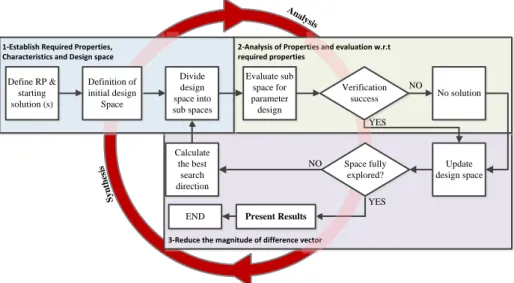
According to [3] the PDD process consists of four main steps:
1. Establish the required properties and selecting initial set of characteristics 2. Analysis of the properties based on the assigned characteristics
3. Comparison of the calculated properties w.r.t. required properties 4. Reducing the magnitude of difference vector between and
Based on these four steps, an algorithm is proposed to apply the CPM/PDD based design space search for finding solutions in a design space via rapid visualization. The algorithm has been programmed in Mathematica® and is platform independent. It utilizes the mCPM model in conjunction with formal logic to search a given design space for a number of solutions that satisfy the required properties.
Fig. 2 illustrates the flowchart of the developed algorithm. The algorithm is divided into three main parts. The first part corresponds to the first step in PDD wherein the designer specifies the set of to be fulfilled. This is accompanied by linking them to the known design space and a list of solutions known earlier. This results into the assignment of initial values to the set of characteristics. The algorithm then systemati-cally divides the given design space into subspaces for the analysis of the
characteris-tics. These steps are carried out via interval arithmetic and mixed integer program-ming and branch and bound technique.
Fig. 2. PDD based design space search algorithm
The second step comprises the step two and three of PDD. Herein the algorithm anal-yses the subsets of the design space to calculate the properties via specified relations. These properties are evaluated against the required properties. The outcome of this step is the evaluation if the part of the design space under analysis holds a valid solu-tion. The evaluation takes place by iterative application of equation 14. This requires evaluation of the quantified expressions. As the scope of this paper consists of para-metric design therefore the algorithm is limited to resolution of existential quantifier only. This is resolved via optimization based constraint propagation as minimization or maximization of relations with inequalities.
The results from the step two are used in the step three of algorithm. This step cor-responds with the last synthesis step of PDD. Results of the design space analysis are used to reduce the design space. The space without solutions is disregarded and the space with solutions is added to the set of solutions. The algorithm then proceeds to select the best direction to search for the properties. This is a directed search which prefers the direction according to the minimum distance between the required proper-ties and the evaluated properties of the analyzed design space i.e.
min 𝑖 ( ) (15)
The results of the algorithm are obtained in form of the explored design space which is stored and manipulated in form of an n-dimensional hypercube whose dimensions are dependent on the number of the characteristics in the problem. For analysis, the parts of the n-dimensional hypercube may be projected visually to a 3 dimensional projection space, allowing the designer to visually analyze the solution
Evaluate sub space for parameter design Update design space END No solution Divide design space into sub spaces Present Results Define RP & starting solution (s) YES NO Calculate the best search direction YES NO
1-Establish Required Properties, Characteristics and Design space
2-Analysis of Properties and evaluation w.r.t required properties
3-Reduce the magnitude of difference vector
Definition of initial design Space Verification success Space fully explored? Analysis Synthes is
space for the number of alternative solutions available. The alternatives can then be analyzed for the adaption to a certain preference via the information available in the hypercube. The algorithm can be programmed to run until all the design space is explored or until a given number of solutions are found.
5
Application
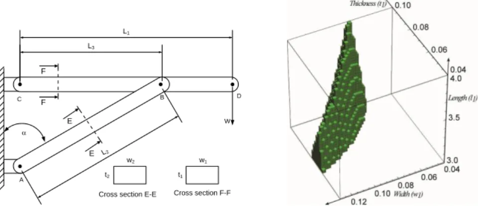
The developed framework is illustrated by an example problem of a structure design adapted from earlier research work (see [10]) as shown in Fig. 3. Contrary to earlier version, the example is made complex by decoupling the dependencies between the two beams in terms of a fixed pin joint location and beam dimensions. The objective is to find out the values for the dimensional characteristics of two beams (length 𝑖, width 𝑤𝑖, thickness 𝑡𝑖 :i=1,2) as well as the positioning of the pin
joints and materials to support a weight W). The example has 8 characteristics, 5 properties (system mass, max. stress, max. force, cost, and factor of safety) and 7 relations linking the characteristics to properties. The relations are non-linear and there is a strong dependency between the characteristics. The mathematical model contains continuous as well as discrete variables representing different characteristics and properties.
Fig. 3. Mechanical structure example with domain visualization
The white cube in the Figure 4 is the starting design space whereas the green cubes correspond to the parametric solutions. A number of solutions are generated that satisfy the required properties and allow the designer to choose the suitable solution.
6
CONCLUSION
CPM/PDD models products and product development processes in a flexible yet formalized way which is developed in this paper further for computer aided-design in redesign problems. These problems are routine design problems characterized by iterative design process to adapt an existing product to varying requirements with intensive CAx involvement. CPM is adapted for providing the basic product model and design process. However in order to apply CPM on CAx level, a mathematical
w2
t2
w1
t1
Cross section E-E Cross section F-F E E F F C W B A D L1 L3 L2 a
model and an algorithmic process is required. This paper proposes a mathematical model and algorithm that intends to unify the two different views of design theory and methodology (DTM) and computer aided design automation.
The model and algorithm developed in this paper is based upon a generalization of existing mathematical models. It is flexible and can be developed further to encompass other considerations such as robust design and uncertainty management. The performance of the algorithm for using the model however currently depends heavily on the number of characteristics. Due to being a branch and bound method the computational complexity of calculation increases and results in high computational effort. It is currently being improved through direct integration with heuristic techniques.
The model can also be further developed and integrated with other concepts in CPM to provide a unified view of different downstream activities in design such as parameter design, tolerance design and analysis, robust design and manufacturing process selection which are interlinked with each other.
7
References
1. Beitz, W., Pahl, G., Wallace, K.: Engineering design: a systematic approach. Springer (2007).
2. Weber, C.: Looking at “DFX” and “Product Maturity” from the Perspective of a New Aproach to Modelling Product and Product Development Processes. Proceedings of the 17th CIRP Design Conference. pp. 85-104 (2007).
3. Weber, C.: An Extended Theoretical Approach to Modelling Products and Product Devel-opment Processes. In: Bley, H., Jansen, H., Krause, F.-L., and Shpitalni, M. (eds.) Pro-ceedings of the 2nd German- Israeli Symposium on Advances in Methods and Systems for Development of Products and Processes. pp. 159-179. , Berlin (2005).
4. Köhler, C., Jan, C., Weber, C.: A Matrix Representation of the CPM/PDD Approach as a Means for Change Impact Analysis. Proceedings of International Design Conference – DESIGN 2008 (2008).
5. Yvars, P.A., Lafon, P., Zimmer, L.: Optimization of mechanical system: contribution of constraint satisfaction method. Computers & Industrial Engineering, 2009. CIE 2009. In-ternational Conference on. pp. 1379–1384. IEEE (2009).
6. Scaravetti, D., Sebastian, P.: Design space exploration in embodiment design: an applica-tion to the design of aircraft air condiapplica-tioners. Internaapplica-tional Journal of Product Develop-ment. 9, 292 (2009).
7. Sébastian, P., Chenouard, R., Nadeau, J.-P., Fischer, X.: The embodiment design con-straint satisfaction problem of the BOOTSTRAP facing interval analysis and genetic algo-rithm based decision support tools. International Journal on Interactive Design and Manu-facturing (IJIDeM). 1, 99-106 (2007).
8. Thornton, Anna, C.: Variation Risk Management: Focusing Quality Improvements in Product Development and Production. 978-0-471-44679-8 (2003).
9. Dantan, J.-Y., Mathieu, L., Ballu, A., Martin, P.: Tolerance synthesis: quantifier notion and virtual boundary. Computer-Aided Design. 37, 231-240 (2005).
10. Scott, M.J., Antonsson, E.K.: Using indifference points in engineering decisions. 11th In-ternational Conference on Design Theory and Methodology ASME,. Baltimore (2000).
![Figure 1. Model of the central analysis a) and synthesis b) steps, after [2]](https://thumb-eu.123doks.com/thumbv2/123doknet/7291105.208345/4.892.191.708.715.951/figure-model-central-analysis-synthesis-b-steps.webp)