HAL Id: tel-01256702
https://hal.archives-ouvertes.fr/tel-01256702
Submitted on 15 Jan 2016HAL is a multi-disciplinary open access archive for the deposit and dissemination of sci-entific research documents, whether they are pub-lished or not. The documents may come from teaching and research institutions in France or
L’archive ouverte pluridisciplinaire HAL, est destinée au dépôt et à la diffusion de documents scientifiques de niveau recherche, publiés ou non, émanant des établissements d’enseignement et de recherche français ou étrangers, des laboratoires
Routage et performances dans les réseaux CPL pour le
Smart Grid
Tanguy Ropitault
To cite this version:
Tanguy Ropitault. Routage et performances dans les réseaux CPL pour le Smart Grid. Modeling and Simulation. Télécom Bretagne; Université de Rennes 1, 2015. English. �tel-01256702�
N° d’ordre : 2015telb0360
S
Soouusslleesscceeaauuddeell’’UUnniivveerrssiittééeeuurrooppééeennnneeddeeBBrreettaaggnnee
Télécom Bretagne
En accréditation conjointe avec l’Ecole Doctorale Matisse Ecole Doctorale – MATISSE
Routage et Performances dans les réseaux CPL pour le Smart Grid
Thèse de Doctorat
Mention : Informatique
Présentée par Tanguy Ropitault Département : RSM
Laboratoire : IRISA/OCIF
Directeur de thèse : Laurent TOUTAIN
Soutenue le 18 Juin 2015
Jury :
Mme Pascale Minet, Chercheur, INRIA Paris Rocquencourt (Rapporteur) M. Thomas Noël, Professeur, Université de Strasbourg (Rapporteur)
M. Laurent Toutain, Enseignant Chercheur, Telecom Bretagne (Directeur de thèse) M. Alexander Pelov, Enseignant Chercheur, Telecom Bretagne (Encadrant)
Acknowledgments
I would like to thank Dr. Alexander Pelov and Dr. Laurent Toutain for guiding me for my thesis. Your precious advices helped me all along the life of this thesis. I did not only meet fount of knowledge, very wisdom and passionated researchers, but also great persons, always looking for helping me to give the best of me. I would thank you all my life.
I would also like to thank Prof. Xavier Lagrange for his precious guidance about the physical part of this thesis. I would also want to thank Prof. Pascale Minet, Prof. Thomas Noël, Dr. Yvonne-Anne Pignolet, Philippe Chiummiento and Dominique Poissonnier for accepting to be part of my jury and for their insightful questions and comments.
My acknowledgments go also to the companies ITRON and Texas Instrument for funding this thesis and their helps for understanding the research regarding to industrial perspectives. I am going to miss those insightful discussions specially with Philippe Chiummiento and Ramanuja Vedantham.
A special thanks to the Hudson Soft company for having created my favorite source of relaxation all along that thesis: Super Bomberman.
I would like also to thank all the person in Telecom Bretagne that I met across all these years. A very special thank to my Argentinian colleagues, Alejandro and Renzo, I stil don’t speak spanish, but I know the important words. A special thank also to Nicolas, who hired me in Telecom Bretagne. Without you, I would not be there now. You were the first one to believe in me. In my turn to admit that I believe in you, and that one day, you may beat me to badminton. I would also like to thank Tanguy, Fabien, Baptiste, Benjamin, Manu, Benoit, Lucien, Sara, Anais, and Marie-Pierre, for all the moments of fun we shared together.
At last but not least, I would like to thank the one that makes it happen. Thanks you Samantha, for your love, your advices, your help. Thank you for being the one you are. May life together be bright and forever.
Abstract
The power grid has begun a major evolution in the past decade, laying the foun-dations of what is known as the Smart Grid. The Smart Grid relies on bidirectional communications in order to enable new functionalities such as efficient manage-ment of production and distribution of electricity, real-time pricing information and consumption feedback to end-users, integration of renewable energy sources and electrical vehicles, and demand response.
One of the key components of the Smart Grid is the Advanced Metering Infras-tructure that enables the interconnection between users and utilities thanks to a new generation of power meters: the Smart Meter. While Smart Meter deployments have already started worldwide at the instigation of governments, a multitude of choices still remains to be done concerning their technical implementations.
Specifically, Smart Meter networking can be based on Power Line Communication (PLC), which is one of the major networking technologies available to utilities. P1901.2, a narrowband PLC has been standardized by the IEEE for usage in the Smart Grid. However, debates are still open for the routing protocol to use for these new high-density, narrowband PLC networks. PLC, being a harsh environment (low bandwidth, noisy, etc.), has most of the characteristics of a Low power and Lossy Network. As a result, the protocol RPL, designed specifically for Low power and Lossy Network, is a prime candidate for routing in IEEE P1901.2 networks.
The goal of this thesis is to study RPL’s behavior in Smart Grid environment and to provide adjustments to its behavior in order to improve the network performance in a narrowband PLC network of Smart Meters.
For that purpose, we implemented a complete IEEE P1901.2 simulation envi-ronment (from physical to applicative layer) in the simulator OPNET, which we validated against a real-world testbed.
Then, we proposed a new way to manage the routing process during RPL’s startup phase. By adapting a specific RPL message emission policy which depends on the network conditions, we ensure a faster creation of the routing topology.
As PLC traffic patterns are different from the ones initially considered for the design of RPL, we introduced a new mechanism to handle link-breakage and non-working Smart Meters. This mechanism, using a slightly modified version of Neigh-bor Unreachability Detection, allows faster detection and reaction to link-breakage. Finally, we proposed a new RPL metric that allows to overcome ETX’s main drawbacks and that can fully benefit of the multi-modulation scheme of IEEE P1901.2 standard.
Resumé
Le réseau électrique a connu récemment une évolution majeure et s’est transformé en un réseau électrique intelligent : le Smart Grid. La bidirectionnalité est au cœur du Smart Grid et permet de mettre en œuvre et de prendre en compte un ensemble de nouvelles fonctionnalités telles que : la gestion efficace de la production et de la distribution d’électricité, l’obtention d’informations temps-réel sur la consommation et le tarifage de l’électricité pour l’utilisateur, l’intégration des énergies renouvelables et des véhicules électriques dans le réseau, et une réponse temps-réel réagissant à la demande afin de réduire les pics de consommation.
Un des éléments majeurs du Smart Grid est l’Advanced Metering Infrastructure qui permet d’assurer l’interconnexion entre utilisateurs et opérateurs énergétiques à l’aide d’une nouvelle génération de compteur : "les compteurs intelligents". Alors que le déploiement de compteur intelligent a déjà commencé dans le monde sous l’instigation des différents gouvernements, une multitude de choix reste encore à faire concernant leur mise-en-œuvre.
Concernant le medium de communication, le Courant Porteur en Ligne (CPL), utilisant les lignes électriques déjà déployées, semble être la solution idéale pour les opérateurs énergétiques. Le standard P901.2 a été standardisé par l’IEEE pour permettre des communication efficaces au sein du Smart Grid. Il préconise l’utilisa-tion du protocole IPv6 mais ne donne aucune indical’utilisa-tion concernant le protocole de routage à utiliser. Le CPL est un environnement extrême de part sa nature (bruits, faibles débits) et peut-être vu comme un Low Power and Lossy Network (LLN) (réseaux à faible puissance et fort taux de perte en Français). Le groupe de travail ROLL a défini le protocole pro-actif RPL spécifiquement pour les LLN et semble, de ce fait, un bon candidat pour les environnements IEEE P1901.2.
Le but de cette thèse est d’étudier le comportement de RPL dans le Smart Grid et d’apporter des améliorations spécifiques pour le Smart Grid afin de garantir un fonctionnement optimal de RPL dans ce type d’environnement.
Dans cette optique, nous avons implémenté par simulation un environnement IEEE P1901.2 complet, de la modélisation du canal physique jusqu’au couche ap-plicative. Nous avons validé ce simulateur en le comparant à une plateforme réelle.
Nous avons ensuite proposé un nouveau moyen de gérer la création de route du-rant la phase de démarrage de RPL. En adaptant spécifiquement les temporisations gérant l’émission de messages RPL, nous garantissons une formation de la topologie de routage plus rapide en prenant en compte l’importance des communications de l’opérateur électrique vers les compteurs intelligents.
conduit à l’élaboration de RPL, nous avons mis en œuvre un nouveau mécanisme pour gérer les liens (ou compteurs intelligents) défaillants. Cette solution utilise une version légèrement modifiée de Neighbor Unreachability Detection qui permet une détection et une réaction plus rapide en cas de lien ou de compteur intelligent non-fonctionnels.
Enfin, nous avons défini une nouvelle métrique pour RPL qui permet de s’af-franchir des problèmes liés à la métrique ETX. Cette métrique, appelée Channel Occupancy, permet de prendre en compte les environnements utilisant un schéma de modulations multiple dans le but de minimiser le temps d’occupation du canal physique.
Resumé en français
Depuis que l’Homme a réussi à appréhender l’électricité, les moyens de production et de distribution de celle-ci ont constamment évolué. Le changement majeur opéré au cours des dernières décennies a été d’intégrer les technologies de l’internet dans le réseau électrique afin de transformer le réseau électrique en un «réseau électrique intelligent». Aujourd’hui, le réseau électrique doit surmonter de nouveaux défis et faire face à de nouvelles contraintes comme :
• Gérer efficacement la production et de la distribution du courant ;
• Fournir des retours aux utilisateurs à propos de de la tarification et de la consommation ;
• Intégrer dans le réseau les énergies renouvelables ;
• Prendre en compte l’apparition des véhicules électriques ;
• Penser à une nouvelle gestion de l’offre et de la demande afin de faire diminuer les pics de charge ;
• Faire face à l’apparition des micros-sources locales de génération de courant. Du point de vue de la distribution, les anciennes générations de réseau électrique permettaient une collecte d’information très limitées (lecture des kWh consommés ou analyse des pics de consommations pour un mois) et ceci d’une manière unidi-rectionnelle. Le nouveau réseau électrique a besoin d’avoir une connaissance précise et temps-réel de la consommation d’énergie et ceci à tous les endroits du réseau, et en plus de pouvoir communiquer de manière bidirectionnelle avec tous les éléments du réseau – l’essence même du réseau électrique intelligent.
Deux principaux domaines peuvent être distingués dans le réseau électrique ac-tuel : le domaine « opéré » en charge de la génération, de la transmission, et de la distribution d’électricité, et le domaine « consommateur ». La frontière séparant ces deux domaines est de la plus haute-importance notamment pour la facturation, mais plus récemment pour des fonctionnalités plus perfectionnées comme par exemple :
• La gestion de la demande comme arrêter la climatisation pour quelques mi-nutes lors d’un pic de charge ;
• Le contrôle d’un flux d’énergie bidirectionnelle comme par exemple un consom-mateur qui a un moyen de produire de l’énergie et qui l’injecte dans le réseau. Cette bordure entre domaine «opéré» et «consommateur » est la plupart du temps matérialisé par le compteur électrique. Obtenir un canal de communication bidirec-tionnelle à l’aide d’un compteur électrique informatisé (le « compteur intelligent ») est donc un des éléments essentiels du réseau électrique intelligent.
Dans certains cas, le compteur électrique intelligent peut être directement joint par l’opérateur énergétique en utilisant une technologie «WAN» (Wireless Area Net-work en anglais) existante (par exemple le réseau cellulaire classique). Cependant, une multitude de facteurs empêche souvent une communication directe et impose de facto l’utilisation de réseaux locaux dédiés (Les «NAN» pour Neighbor Area Net-work en anglais) qui connectent les compteurs à proximité comme ceux d’un quartier ou ceux connectés au même transformateur électrique.
Le système englobant les compteurs intelligents, les réseaux nécessaires à leur communication (WAN et NAN), et le système de gestion est appelé «AMI» (pour Advanced Metering Infrastructure en anglais). L’AMI repose sur des NAN robustes et efficaces pour transporter l’information entre les compteurs électriques intelligents et les concentrateurs de données. Les concentrateurs de données sont les éléments connectant les LAN et les WAN et peuvent varier en complexité : d’un simple répé-teur à une passerelle applicative complète. Dans de la cadre de cette thèse, nous nous focalisons sur l’environnement AMI et plus spécifiquement sur les communications entre les concentrateurs de données et les compteurs électriques intelligents.
L’AMI est un élément clé du réseau électrique intelligent et permet de surveiller en temps-réel la consommation électrique, permettant de ce fait à l’opérateur éner-gétique d’agir et de réagir à l’évolution du système. Au moment de la rédaction, il y a environ 45 millions de compteurs électrique intelligent déjà installés par trois pays européens (la Finlande, l’Italie et la Suède). La Commission Européenne a re-commandé que 200 millions de compteur électrique intelligent soient déployés d’ici à 2020 (représentant environ un taux d’équipement de 72% du parc européen de compteur). Malgré les récents efforts fournis pour définir l’architecture du réseau électrique intelligent et le fait que le déploiement des compteurs électriques intel-ligent ait déjà commencé à l’échelle mondiale, le réseau électrique intelintel-ligent est aujourd’hui plus une vision qu’une réalité et beaucoup de choix restent encore à faire par les opérateurs énergétiques et le marché comme de choisir :
• Le medium physique de communication (sans-fil ou filaire) c’est-à-dire le me-dium utilisé pour transporter les données ;
• Les protocoles réseaux nécessaires à la transmission et au routage du trafic entre les compteurs intelligents et les opérateurs énergétiques.
Concernant le medium physique, deux principales options sont disponibles : un environnement filaire ou sans-fil. Une des solutions les plus prometteuses pour trans-porter les données au sein du réseau électrique est une solution filaire : le « CPL » (pour Courant Porteur en Ligne). Le CPL permet de transporter les données sur les lignes électriques et offre le gros avantage, comparé aux solutions sans-fil, d’un coût de déploiement limité vu que les lignes électriques sont déjà existantes. Par consé-quent, le CPL a été choisi par les opérateurs énergétiques et l’industrie des compteurs intelligents comme un candidat potentiel pour le medium physique. Cependant, à cause de ses caractéristiques intrinsèques extrêmes (environnement bruité, faible
dé-bit, etc.), l’utilisation du CPL dans les réseaux électriques intelligents représente différents challenges qui doivent être résolus à l’aide de solutions CPL spécifiques. A cette fin, une grande partie des industriels et des experts mondiaux ont défini le protocole « P1901.2 » qui a été standardisé à l’IETF. Ce protocole utilise des fré-quences à bande étroite (<500kHz) qui peuvent offrir un débit jusqu’à 500kbps en fonction de la régulation en vigueur. Notre thèse étudie le protocole IEEE P1901.2 plus particulièrement pour la bande CENELEC A, c’est-à-dire la bande réservée pour les opérateurs énergétiques en Europe. Le choix du medium physique de com-munication n’est pas le seul choix devant être fait par les opérateurs énergétique : le choix des protocoles réseaux de communication est de la plus haute importance. IEEE P1901.2 impose l’utilisation d’IPv6. Les motivations pour choisir une solution purement IP sont basées sur le succès d’IP comme couche de convergence (plus de deux milliards de personnes utilisent l’internet quotidiennement) et aussi sur son ancienneté (plus de 30 années de développement et d’amélioration) qui facilitent des standards ouverts et interopérables. Le protocole IPv6, apportant de nombreuses améliorations au protocole IPv4 (autoconfiguration facilitée, un espace d’adressage plus grand, etc.) est la solution idéale pour les nouveaux réseaux et a donc été choisie par les opérateurs énergétiques pour le développement de réseaux intelligents.
Alors qu’IPv6 a été largement adopté comme un élément clé du réseau électrique intelligent, les débats sont toujours en cours concernant le protocole de routage à utiliser. Le CPL, avec ses caractéristiques, peut être vu comme un réseau à faible puissance et fort taux de perte («LLN» en anglais pour Low power and Lossy Net-work) c’est-à-dire un réseau composé d’appareils fortement contraints. Le groupe de travail ROLL de l’IETF a défini un protocole spécifiquement pour les LLN. Ce protocole, «RPL», permet de construire et d’installer des topologies de routage sans boucle grâce à une structure appelé DAG, centrées sur une seule destination : le puits de données. Cela permet d’avoir des routes bidirectionnelles depuis les cap-teurs jusqu’au puits de données (des compcap-teurs intelligents au concentrateur de données dans l’environnement AMI) ce qui sied totalement au premier objectif du réseau électrique intelligent : la bidirectionnalité des communications. RPL a été principalement créé de façon à optimiser le trafic MultiPoint-a-Point (même si il permet le trafic Point-a-Point et Point-a-Multipoint), et cherche plus particulière-ment à optimiser les routes des capteurs au puits de données ; Jusqu’à présent, les performances du protocole de routage RPL ont été étudiées dans la littérature dans le contexte des réseaux sans-fil. Ainsi, peu de résultats sont disponibles dans les en-vironnements CPL et encore moins dans les architectures AMI. Les motifs de trafic ont été identifiés et catégorisés en deux parties :
• Des compteurs intelligents au point terminal de la communication («M2HE» pour Meter to Head-End en anglais)
• Du point terminal de communication aux compteurs intelligents. (“HE2M” pour Head-End to Meter en anglais)
Le trafic HE2M a une importance capitale car il permet à l’opérateur énergétique de communiquer avec les compteurs intelligents en fonction des évènements (par exemple stopper des équipements, déclencher des lectures spontanées de compteurs, ou mettre à jour le micrologiciel des compteurs). RPL doit donc être étudié dans les environnements AMI PLC pour analyser son efficacité et ceci quel que soit le type de trafic (M2HE ou HE2M) afin de déterminer si des optimisations spécifiquement adaptées aux AMI sont nécessaires.
Pour étudier les performances de RPL, nous avons architecturé et implémenté un simulateur IEEE P1901.2 complet en utilisant le simulateur OPNET. Cette phase a consisté à proposer et à mettre en œuvre un modèle de canal physique P1901.2, et aussi le développement complet du protocole P1901.2. En plus du protocole de routage RPL, nous avons implémenté les protocoles de routage LOAD et LOADng afin d’avoir une base de comparaison. En effet, LOAD et son évolution LOADng, ont été choisis comme protocole de routage par défaut pour le protocole « G3-PLC », un autre standard PLC pour les fréquences à bande étroite définit spécifiquement pour les réseaux électrique intelligent. Pour évaluer la technologie CPL, l’industrie des AMI se repose sur des métriques observées à large-échelle (1500 nœuds par concentrateur de données), avec une large base de topologies (rurale, urbaine, ou mixte) et sur différents profils de bruits et d’impédances. Les évaluations sur le terrain sont généralement limitées à un faible nombre de nœuds, de topologies, et de profils. La principale limitation provient d’un problème de coût associé au déploiement de pilotes de test. La seule alternative viable au déploiement terrain est la simulation. Nos résultats de simulations ont été comparés et validés avec des résultats obtenus sur le terrain afin de garantir la qualité de la mise en œuvre de l’implémentation dans le simulateur.
La contribution principale de notre thèse est de proposer des adaptations et des optimisations au protocole RPL spécifiquement adaptées à l’environnement P1901.2 AMI. Les améliorations proposées peuvent se classifier en deux catégories :
• Formation des routes : Le processus consistant à créer des routes bidirection-nelles entre les compteurs intelligents et le concentrateur de données durant le démarrage du réseau ;
• Gestion des routes : La phase pendant laquelle RPL atteint son état sta-tionnaire et où les routes doivent être maintenues et mises à jour selon les conditions du réseau (qualité du lien qui change, lien qui casse, ou compteur intelligent non-opérationnel).
Notre objectif est de minimiser le surplus de signalisation, le temps de conver-gence, le temps de réparation dans le cas d’un lien non-fonctionnel, et le délai de bout-en-bout, tout en maximisant le taux de transmission. Nous proposons une ap-proche distribuée (4Dia) pour améliorer le temps de convergence durant la phase de formation des routes. Cette méthode calcule dynamiquement l’émission des mes-sages de signalisation en fonction des conditions du réseau, et ceci afin d’éviter les
congestions et d’accélérer le processus de formation des routes. Nous introduisons aussi une nouvelle définition du temps de convergence pour les environnements AMI en soulignant le fait que la bidirectionnalité des communications entraine des nou-velles exigences. De ce fait, le temps de route formation doit non seulement prendre en compte le temps pour former les routes descendantes mais aussi le temps de for-mation des routes montantes, contrairement à ce qui est définit dans la littérature où seul le temps pour former les routes descendantes est pris en compte.
Nous améliorons la gestion des routes en ajoutant une nouvelle méthode pour réagir au cassure de lien ou au lien non-fonctionnel : FRLD. Ce mécanisme est basé sur une version légèrement modifiée de NUD. Il permet d’accélérer la réaction au lien non-fonctionnel ainsi que de procéder à l’installation des routes nécessaires pour une réaction rapide. Nous réduisons aussi le surplus de signalisation en ajoutant un nouveau critère pour gérer l’émission des messages DAO en fonction du retour de l’opérateur énergétique. Finalement, nous avons introduit une nouvelle métrique pour RPL : Channel Occupancy. Cette métrique cherche à minimiser l’occupation globale du canal en calculant le cout du chemin en fonction de la modulation utili-sable pour chaque lien. Ainsi, les routes sont construites en minimisant l’occupation du canal. Contrairement à la métrique ETX, Channel Occupancy tend à utiliser plus de saut pour transmettre les données mais permet de réduire le délai de bout en bout et de maximiser le taux de transmission des données.
List of Publications
International Conferences
T. Ropitault, A. Lampropulos, A. Pelov, L. Toutain, R. Vedantham, and P. Chiummiento. Realistic model for narrowband PLC for advances metering
infras-tructure, In IEEE International Conference Smart Grid Communications
(Smart-GridComm), 2013.
T. Ropitault, A. Lampropulos, A. Pelov, L. Toutain, R. Vedantham, and P. Chi-ummiento. Doing it right 2014; recommendations for RPL in PLC-based networks
for the smart grid, In IEEE International Conference Smart Grid Communications
(SmartGridComm), 2014.
T. Ropitault, A. Lampropulos, A. Pelov, L. Toutain, R. Vedantham, and P. Chiummiento. Optimizing PLC Networks for the Smart Grid with a new
multi-modulation RPL metric – Channel Occupancy, submitted to IEEE International
Conference Smart Grid Communications (SmartGridComm), 2015.
T. Hartmann, F. Fouquet, J. Klein, Y. Le Traon, A. Pelov, L. Toutain, T. Ropi-tault. Generating realistic Smart Grid communication topologies based on real-data, In IEEE International Conference Smart Grid Communications (SmartGridComm), 2014.
Acronyms
4Dia Distributed Dynamic DelayDAO interval adjustment
6LoWPAN IPv6 over Low power Wireless Personal Area Networks ADRM Aggressive Downward Route Management
ADTL Average Data Transmission Level AMI Advanced Metering Infrastructure
AODV Ad Hoc On-Demand Distance Vector Protocol APTL Average Preamble Transmission Level
ARIB Association of Radio Industries and Businesses ASTL Average Sub-band Transmission Level
ATN Average Total Noise BB Broadband
CENELEC Committee for Electrotechnical Standardization CIFS Contention Interframe Space
CO Channel Occupancy
COALE Channel Occupancy Active link-estimation
CSMA/CA Carrier Sense Multiple Access with Collision Avoidance CTP Collection Tree Protocol
D8PSK Differential Eight Phase Shift Keying DAG Directed Acyclic Graph
DAO ACK DAO Acknowledgment DAO Destination Advertisement Object
DBPSK Differential Binary Phase Shift Keying DC Data Concentrator
DIO DAG Information Object DIS DAG Information Solicitation DIS-NA DIS No Answer
DODAG Destination Oriented DAG
DQPSK Differential Quaternary Phase Shift Keying DSP Digital Signal Processor
DTSN DAO Trigger Sequence Number E2E End-to-End
EIFS Extended Interframe Space ETX Expected Transmission Count
EWMA Exponentially Weighted Moving Average FCC Federal Communications Commission
FCH Frame Control Header
FRLD Fast and Reactive Link-failure Detection FSM Finite State Machine
G3-PLC G3-PLC
HAN Home Area Network HE2M Head-End-to-Meter
IEEE Institute of Electrical and Electronics Engineers IETF Internet Engineering Task Force
IFS Inter Frame Spacing IP Internet Protocol
IPv6 Internet Protocol version 6 LF NB Low Frequency Narrowband LF Low Frequency
LLN Low power and Lossy Network
LOAD 6LoWPAN Ad Hoc On-Demand Distance Vector Routing
LOADng Lightweight On-demand Ad hoc Distance-vector Routing Protocol Next
Generation
LQI Link Quality Indicator LV Low Voltage
M2HE Meter-to-Head-End MAC Medium Access
MANET Mobile Ad-hoc Networks
MDMS Meter Data Management Systems MP2P Multipoint-to-Point
MRHOF Minimum Rank with Hysteresis Objective Function MV Medium Voltage
NAN Neighborhood Area Network NB Narrowband
NIST National Institute of Standards and Technology NM Node Model
NS Neighbor Solicitation
NUD Neighbor Unreachability Detection
NUD-PP Neighbor Unreachability Detection for Preferred Parent OCP Objective Code Point
OF Objective Function OF0 Objective Function Zero
OFDM Orthogonal frequency-division multiplexing ORPL Opportunistic RPL
OS Operating System P2MP Point-to-Multipoint P2P Point-to-Point
PCS Physical Carrier Sense PDR Packet Delivery Ratio PHY Physical
PLC Power Line Communication PM Process Model
RERR Route Error
RFC Request For Comments RIFS Response Interframe Space
ROBO Robust Orthogonal Frequency Division Multiplexing ROLL Routing over Low-Power and Lossy Links
RPL RPL: IPv6 Routing Protocol for Low-Power and Lossy Networks RREP Route Reply
RREP-ACK Route Reply - Acknowledgment RREQ Route Request
SG Smart Grid
SINR Signal-To-Noise Interference-Ratio SM Smart Meter
SNR Signal Noise Ratio TM Tone-Map
TMReq Tone-Map Request TMResp Tone-Map Response UNB Ultra Narrow Band WAN Wide Area Network WSN Wireless Sensor Network
Contents
Acknowledgments i
Abstract iii
Resumé vi
List of Publications xi
List of Publications xiii
1 Introduction 1
1.1 Contributions . . . 5 1.2 Thesis outline . . . 6
2 IEEE P1901.2: A narrowband PLC protocol for the Smart Grid 9
2.1 The Smart Grid . . . 9 2.2 The AMI . . . 11 2.2.1 AMI technologies . . . 11 2.2.2 PLC classification . . . 12 2.2.3 AMI traffic pattern . . . 13 2.3 IEEE P1901.2 . . . 14 2.3.1 Physical layer . . . 15 2.3.2 MAC layer . . . 16 2.3.3 Tone-Map mechanism . . . 18 2.4 Conclusion . . . 18 3 Routing Protocols 21 3.1 Routing protocols . . . 21 3.1.1 Reactive Protocols . . . 21 3.1.2 Proactive Protocols . . . 22
3.1.3 From MANET to ROLL . . . 22 3.1.4 LLN specific routing requirements . . . 23 3.1.5 The need for new routing protocols for LLNs . . . 24 3.2 LOAD and LOADng . . . 24 3.3 RPL . . . 26 3.3.1 Topology construction . . . 27 3.3.2 RPL messages timer . . . 31 3.3.3 Objective Function . . . 32 3.3.4 Metrics . . . 34 3.3.5 RPL Implementations . . . 35 3.4 RPL in the literature . . . 35 3.4.1 PLC and RPL studies . . . 36 3.4.2 RPL and WSN . . . 38 3.5 Conclusion . . . 42 4 Simulator Overview 43
4.1 Network Simulator choices . . . 43 4.2 Simulator’s overview . . . 44 4.3 Physical Model . . . 44 4.3.1 Overview . . . 44 4.3.2 SNR computation . . . 47 4.3.3 Errors Computation . . . 49 4.4 Simulator’s validation . . . 49 4.4.1 Methodology . . . 50 4.4.2 Validation . . . 50 4.5 Conclusion . . . 54 5 Route Formation 57 5.1 Route Formation . . . 57 5.1.1 Definition . . . 57 5.1.2 Route Formation with vanilla Contiki . . . 58 5.2 The DelayDAO problem for downward routes creation . . . 59 5.2.1 Reference scenario . . . 59
5.2.2 Route Formation process . . . 61 5.2.3 Performance degradation and hidden nodes . . . 61 5.2.4 Parameter exploration . . . 64 5.3 The need for a dynamic DelayDAO per node . . . 64 5.3.1 Optimistic-multiplicative 4Dia (OM-4Dia) . . . 65 5.3.2 Optimistic-additive 4Dia (OA-4Dia) . . . 65 5.3.3 Pessimistic 4Dia (P-4Dia) . . . 66 5.4 Results . . . 66 5.4.1 Optimistic 4Dia algorithms . . . 67 5.4.2 Pessimistic 4Dia . . . 67 5.4.3 Results interpretations . . . 67 5.5 Discussion and recommendations . . . 69 5.6 Conclusion . . . 70
6 Route Maintenance 71
6.1 The ETX metric . . . 72 6.2 The link-failure detection . . . 73 6.3 Fast link-failure detection for Preferred Parent . . . 77 6.3.1 Neighbor Unreachability Detection . . . 77 6.3.2 Fast link-failure detection for Preferred Parent:NUD-PP . . . 78 6.3.3 Fast link-failure reaction: Aggressive Downward Route
Man-agement (ADRM) . . . 78 6.3.4 Fast and Reactive Link-failure Detection . . . 78 6.3.5 Consequences on signaling overhead . . . 79 6.3.6 FRLD and DTSN . . . 79 6.4 Related work . . . 80 6.5 Conclusion . . . 81
7 A new metric for RPL: Channel Occupancy 83
7.1 Problem Statement . . . 84 7.2 The Channel Occupancy metric . . . 85 7.2.1 Channel Occupancy with active link estimation . . . 86 7.2.2 Channel Occupancy expression . . . 88
7.3 Channel Occupancy for OF0 . . . 88 7.4 ChannelOccupancy for MRHOF . . . 90 7.5 Channel Occupancy and ETX . . . 91 7.6 Performance evaluation – Channel Occupancy vs vanilla Contiki (MRHOF
with ETX) . . . 92 7.7 Comparison to reactive routing protocols for LLN: LOAD and LOADng 95 7.7.1 LOAD and LOADng . . . 96 7.7.2 LOAD, LOADng and RPL . . . 96 7.8 Conclusion . . . 97
8 Conclusion and perspectives 99
8.1 Conclusion . . . 99 8.2 Perspectives . . . 100 8.2.1 Real on-the-field experimentations . . . 100 8.2.2 Multiple Technology Management . . . 100 8.2.3 Composite Metric . . . 100 8.2.4 Hybrid approach . . . 101
A LOAD and LOADng differences 103
List of Figures 105
List of Tables 109
1
Introduction
Strange about learning;the farther I go the more I see that I never knew even existed. A short while ago I foolishly thought I could learn everything - all the knowledge in the world. Now I hope only to be able to know of its existence, and to understand one grain of it. Is there time? Daniel Keyes, Flowers for Algernon Ever since man has tamed electricity, the means for producing and distributing it have been in gradual evolution. The biggest change to the power grid in the past several decades is the recent effort to deploy Internet technologies throughout the grid in order to turn the grid into a Smart Grid (SG). Nowadays, more than ever, the grid has to meet new challenges and constraints:
• Efficient management of production and distribution of power;
• Provide feedbacks about real-time pricing information and consumption to users;
• Integration of renewable energy sources, electrical vehicles;
• Real-time demand response and management strategies for lowering peak de-mand and overall load, through appliance control;
• Integration of locally distributed micro-generation sources.
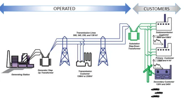
From the distribution part, former generation of power grid only allowed to collect limited informations (kWh reading and possibly peak kW demand for the month) in a one-way manner. The new power grid needs to have a real-time, accurate knowledge of the actual energy consumption all along the grid and to be able to communicate bidirectionally with all the elements connected to the grid – the essence of the SG. We can see on Figure 1.1 that two domains can be distinguished on the current power grid: the operated (generation, transmission and distribution of electricity) and the customers domain. The frontier between the two is of crucial importance – classically for accounting purposes, and since recently – for enhanced grid operation
1
Figure 1.1: The power grid. (source: www.nerc.com)
and control, e.g. demand side management (stopping air conditioning for a couple of minutes during peak hours) or two-way energy flow control (e.g. when a customer has local energy production and injects it to the grid). This border is materialized in the majority of the cases by the power meter.
Having a two-way communication channel with a computerized power meter, i.e.
Smart Meter (SM), is therefore one of the pillars of the Smart Grid. In some cases,
the SM can be reached directly through an existing Wide Area Network (WAN) technology (such as a cellular network), but a multitude of factors often imposes the usage of a dedicated local network which connects the meters in proximity, such as a neighborhood or the ones connected to the same power transformer – aNeighborhood
Area Network (NAN).
The system which englobes the SMs, the networks necessary to communicate with them (NAN and WAN), and the backend management system is called Advanced
Metering Infrastructure (AMI). AMI relies on efficient and robust NAN to carry
information between power meters and a Data Concentrator (DC). DCs are the elements which connect the NAN to the WAN, and can vary in complexity – from a simple repeater to a full-featured application-level gateway (Figure 1.2). In this thesis, we are going to focus on AMI environment and more specifically on commu-nications between DC and SMs – the last-mile of an AMI. AMI is a key enabler of the Smart Grid as it permits to monitor in real-time the power consumption and allows utilities to act and react to system’s evolution.
At the present time, there are close to 45 million Smart Meters already installed in three European Member States (Finland, Italy and Sweden). The European Commission stated that by 2020, 200 million SMs for electricity (representing
ap-CHAPTER 1. INTRODUCTION
1
WAN Medium Voltage 3 phases Power Domain: Low Voltage single phase current Substation Data Concentrator Back Office Data Domain: Neighborhood Area NetworkFigure 1.2: Elements of an Advanced Metering Infrastructure.
proximately 72% of all European consumers) should be deployed [EL14]. Despite recent efforts produced to define a Smart Grid framework [GOEED14] and the fact that SMs deployments already started worldwide, Smart Grid is today more a "vi-sion" than an actual design and a wide variety of choices has yet to be made by utilities, such as selecting:
• Physical medium (wireless or wired) i.e. the medium used to propagate the data;
• Upper layer network stack in order to transmit and route traffic between SMs and utilities.
Concerning the physical medium, two choices can be made: wired or wireless medium. One of the most promising solutions to carry data in the power grid is a wired solution: Power Line Communication (PLC). PLC allows to transport data on the electric power line and offers a big advantage compared to wireless solutions: as power lines are already installed, PLC deployment cost is limited. Thus, PLC has been selected by utilities and power meter industry as a potential candidate for physical medium. However, due to its intrinsic harsh characteristics (noise, low throughput, etc.), usage of PLC in Smart Grid environment presents specific challenges that need to be addressed with adapted PLC solutions. To that purpose, a large part of PLC industry’s technical experts and stake holders specified the P1901.2 [IEE10] which has been standardized by Institute of Electrical and
Electronics Engineers (IEEE). It uses low frequency narrowband (<500kHz) that
1
Figure 1.3: Regulatory frequency map. (source:[IEE10])
thesis, our work is based on IEEE P1901.2, and more precisely in Committee for
Electrotechnical Standardization (CENELEC) A band: the band reserved for power
companies in Europe (Figure 1.3).
The choice of physical medium is not the only one that needs to be made by util-ities, upper layer network stacks is of crucial importance. IEEE P1901.2 imposes the use of Internet Protocol version 6 (IPv6). The motivation to choose an IP so-lution is based on IP success as a convergence layer (more than two billions people use the Internet daily) and its past history (30 years of technology development) which facilitates open standards and interoperability. IPv6, with its new function-alities (auto-configuration, larger address space, etc.) is the ideal solution for new networks and has thus been selected by utilities for Smart Grid’s deployment.
While IPv6 has been widely adopted as a key component of SG environment, debates are opened and ongoing for the routing protocol to use. PLC networks, with their characteristics, can be seen asLow power and Lossy Network (LLN) (i.e. a network of constrained devices). The Internet Engineering Task Force (IETF) working group Routing over Low-Power and Lossy Links (ROLL) designed a rout-ing protocol specifically for LLN. This protocol, RPL: IPv6 Routing Protocol for
Low-Power and Lossy Networks (RPL) [WTB+12], allows to construct and
in-stall loop-free routes thank to a Directed Acyclic Graph (DAG) rooted at a single destination: the sink. It permits to have bidirectional routes from sensors to the sink (from SMs to the DC in AMI architecture) which fits with the SG primary goal: bidirectionality of the communications. RPL has been mainly designed for
Multipoint-to-Point (MP2P) traffic (even if it allows Point-to-Point (P2P), as well
asPoint-to-Multipoint (P2MP) traffics), and more precisely aims to optimize routes from the sensors to the data sink.
CHAPTER 1. INTRODUCTION
1
At present, RPL performances have been widely studied in the literature in thecontext of Wireless Sensor Network (WSN), but few results are available about RPL in PLC environment and even less in PLC AMI architecture. AMI environment traffic patterns have been identified and categorized in two parts in [draa]:
• Meter-to-Head-End (M2HE); • Head-End-to-Meter (HE2M).
HE2M traffic is of crucial importance as it allows utilities to communicate with SMs for event-based traffic (e.g. to stop some equipments, to trigger spontaneous meter readings, or to update firmware). RPL must thus be studied in AMI PLC environment to analyze its effectiveness for every AMI typical traffic pattern and to determine if optimizations specially tailored for AMI are needed.
1.1 C
ONTRIBUTIONS
In order to study RPL protocol performances, we designed and implemented a complete IEEE P1901.2 simulator under OPNET. This phase includes the proposi-tion and implementaproposi-tion of a IEEE P1901.2 PLC channel model as well as the com-plete development of a IEEE P1901.2 RPL simulator under OPNET . We also
imple-mented 6LoWPAN Ad Hoc On-Demand Distance Vector Routing (LOAD) [LOAa]
and its evolution Lightweight On-demand Ad hoc Distance-vector Routing Protocol
Next Generation (LOADng) [LOAb]. We decided to use LOAD and LOADng as
baseline comparison. Indeed, LOAD and LOADng protocols have been chosen as the default routing protocols for G3-PLC [G3-], an other narrowband PLC standard defined for Smart Grid. To evaluate a PLC technology, the AMI industry relies on performance metrics reported on large scale cells (1500 nodes per data concentra-tor), on a wide range of topologies (rural, urban, mixed) and on different impedance and noise profiles. Real field evaluations are generally limited to a small numbers of nodes, topologies and noise profiles. The main limitation is the resources and logistic costs related to pilot deployments. The only alternative to real field deploy-ments are simulation-based evaluations. Our simulation results have been validated against real testbed implementation [RLP+] in order to have the needed confidence
for results analyses.
Our main contribution is to propose adaptations and optimizations to RPL pro-tocol specially tailored for IEEE P1901.2 AMI environments. Enhancements can be categorized in two parts:
• Route Formation: The process to create bidirectional routes between SMs and DC at RPL startup [RLP+14];
• Route management: The phase when RPL reaches its steady-state and that routes need to be maintained and updated based on events (link-quality change, link-breakage, or non-working SM).
1
1.2. THESIS OUTLINE
Our goal has been to minimize RPL overhead, convergence time, repair time in case of link-breakage andEnd-to-End (E2E) delay, while maximizing Packet
Deliv-ery Ratio (PDR). We propose a distributed approach solution Distributed Dynamic DelayDAO interval adjustment (4Dia) [RLP+14] in order to improve route
forma-tion convergence time. This method, computing dynamically signaling messages emission regarding to network conditions in order to avoid congestions, allows to speed-up the route formation process in AMI context. We also introduced a new definition for convergence time in AMI environment by highlighting the fact that bidirectional communication brings new requirements.
We enhance route management by adding a novel method to react to link-breakage or non-working SM: Fast and Reactive Link-failure Detection (FRLD). This mechanism is based on a slightly modified version of Neighbor Unreachability
Detection (NUD). It allows to accelerate both link-breakage and non-working SM
detection as well as the installation of new needed routes to react to that outage. We also reduce RPL signaling overhead by adding new criteria to manage DAO emission based on utilities feedbacks.
Finally, we introduce a new metric for RPL: theChannel Occupancy (CO) metric [RLP+15]. CO aims to minimize the global channel occupation by computing path
costs based on the usable modulation for each link. Thus, routes are constructed by minimizing channel occupancy. In opposition to Expected Transmission Count (ETX) [DCABM03] metric, CO may use more hops to relay data but End-to-End delay is going to be lowered while PDR is maximized. We designed the metric usage for both RPL Objective Functions (OFs) defined so far: Objective Function
Zero (OF0) and Minimum Rank with Hysteresis Objective Function (MRHOF).
Our solution is implemented for IEEE P1901.2 environment but could be applied to other environments.
1.2 T
HESIS OUTLINE
Chapter 2 presents the context of this thesis and more particularly introduces the Smart Grid and one of its key component, the AMI, prior to present a classification of existing PLC solutions to locate IEEE P1901.2 in the PLC galaxy. The Chapter will be concluded by a description of IEEE P1901.2.
Chapter 3 describes in details RPL routing protocol: what lead to its design genesis, its companion draft as well as its main mechanism. We introduce also in this chapter two other candidate routing protocols forLow power and Lossy Network
(LLN): 6LoWPAN Ad Hoc On-Demand Distance Vector Routing (LOAD) and
Lightweight On-demand Ad hoc Distance-vector Routing Protocol Next Generation
(LOADng).
Chapter 4 introduces the simulator developed in this thesis by a short overview of its implementation, its mains characteristics and the physical model used for
CHAPTER 1. INTRODUCTION
1
representing PLC channel, as well as a validation against a real-testbed.Chapter 5 focuses on a weakness of RPL protocol for Smart Grid we detect when we analyze route formation’s phase and the proposed mechanism to overcome that weakness: 4Dia .
Chapter 6 describes Fast and Reactive Link-failure Detection (FRLD) solution that enables fast and reactive link-failure detection specially tailored for taking into account SG traffic pattern characteristics.
Chapter 7 highlights the main drawbacks ofExpected Transmission Count (ETX) metric in SG environment and introduces a new metric for RPL: Channel Occupancy (CO).
Chapter 8 presents the general conclusions of this work and the possible future research directions.
1
2
IEEE P1901.2: A
narrowband PLC protocol
for the Smart Grid
IEEE P1901.2 is a standard defined for low frequency (less than 500 kHz) nar-rowband communications PLC devices via alternating current and direct current electric power lines. This standard supports indoor and outdoor communications over Low Voltage (LV) (less than 1000 V) and Medium Voltage (MV) (1000 V to 72 kV) power lines and through associated transformers in both urban and long-distance rural applications. Data rates will vary up to 500 kbps depending on the application requirements and network conditions. This standard addresses grid to utility meter, grid automation, electric vehicle to charging station, and within home area networking communications scenarios.
In this chapter, prior to describe IEEE P1901.2, we introduce the Smart Grid (SG) in Section 2.1 in order to understand its role and the new challenges associated to it. Then, in Section 2.2, we describe a key component of the SG: the Advanced
Metering Infrastructure (AMI). A classification of PLC is then presented for
under-standing the position of IEEE P1901.2 in respect to the existing standards. Finally, IEEE P1901.2 is described in Section 2.3.
2.1 T
HE
S
MART
G
RID
Domain Role
Customer End-user of electricity (households, companies) Operators Operators and participant in electricity markets
Service provider Organizations providing services
to electrical customers and to utilities
Operations Manager of movement of electricity
Generation Generators of electricity
Transmission Carriers of bulk electricity over long distances Distribution Distributors of electricity to and from customers
Table 2.1: NIST conceptual domains for the Smart Grid.
The Institute of Electrical and Electronics Engineers (IEEE) defines the Smart Grid as "a next-generation electrical power system that is typified by the increased
2
2.1. THE SMART GRID use of communications and information technology in the generation, delivery and consumption of electrical energy". However, Smart Grid is such a complex
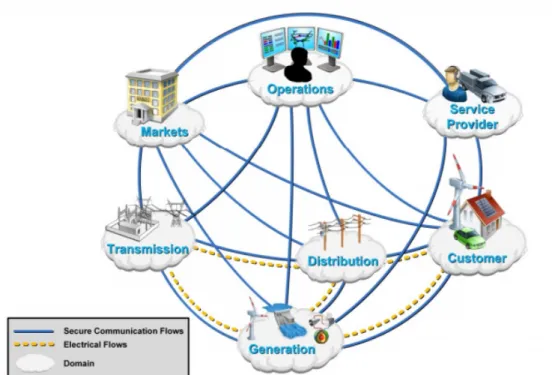
sys-tem which involves several technical domains (IT, Telecom, Embedded Platforms, Advanced Control, Cyber Security, Power Electronics and Energy Engineers and Specialists) that its definition may vary depending on each domain perspectives. The National Institute of Standards and Technology (NIST) defined a Framework and Roadmap for Smart Grid. It analyses existing standards, as well as major or-ganisations involved, and provides recommendations for addressing the Smart Grid challenges [NIS]. The NIST introduces in [NIS] a conceptual model for the power grid (Figure 2.1) which identifies several domains (Table 2.1) and their interactions to enable the implementation of the Smart Grid.
Figure 2.1: Conceptual domains interactions Grid. (source: www.nist.com) These different domains interact in order to create additional functionalities com-pared to the former power grid:
• Enables real-time analysis of power system components performances across large areas in order to improve efficiency and react before perturbations occur; • Provides an opportunity for consumers to adapt their electrical consumption by reducing or shifting their electricity usage during peak periods depending on real-time pricing (Demand Response);
• Integrates generation (renewable energy) and/or electric storage systems; • Manages the emergence of electrical vehicle.
From communications perspective, Smart Grid appears as the interconnection of several networks (Figure 2.2): the Home Area Network (HAN), the Neighborhood
CHAPTER 2. IEEE P1901.2: A NARROWBAND PLC PROTOCOL FOR THE SMART GRID
2
Area Network (NAN) and the Wide Area Network (WAN). The HAN is the
net-work that allows communications between smart devices and appliances within the household (or buildings). For examples, it could be the display of real-time energy consumption on a smartphone, as well as automatically turning-off a thermostat based on utilities pricing. The NAN is the local network that permits the commu-nication between each device in a limited area (e.g. neighborhood). In the Smart Grid context, Smart Meters are connected with a Data Concentrator (DC) over a NAN. The WAN allows device in a large area to communicate. From Smart Grid perspective, this network makes the interconnection between utilities and the data collected by the Smart Meters (SMs) in the NAN, the DC being in charge of NAN and WAN interconnexion.
Figure 2.2: Smart Grid from communications Point of View. (source: IEEE)
2.2 T
HE
AMI
TheAdvanced Metering Infrastructure (AMI) is the part of the Smart Grid that allows to connect SMs to the utilitiesMeter Data Management Systems (MDMS) in order to manage collected data. From communication networks perspective, AMI is using NAN and WAN. The main architecture used for AMI is made of one DC that acts as a gateway between the WAN (to the utilities) and the NAN (the gathered information from the SMs). In this thesis, we focus on the NAN communication network between SMs and DC.
2.2.1 AMI technologies
Various technologies (wired or wireless) can be used to connect SMs and DC [GSW10]:
• wired: PON (GPON, EPON ), RFoG-DOCSIS, PLC;
• wireless: RF Mesh/802.15.4g, Wimax 802.16d/e, RF Radio Pto-Mtp/MAS,
3G-3GPP/1XRTT/EVDO, GPRS/EDGE/HSDPA, WLAN 802.11 n/g, 802.2.15.4 / ZigBee.
2
2.2. THE AMI
Compared to wireless solutions, PLC offers several advantages. Indeed, the power-line infrastructure is already existing and reusing it allows to lower the de-ployment costs. Additionally, SMs location is not always compatible with the use of wireless technologies (for example, it is not rare in Europe to find meters inside household surrounded with concrete walls or steel). The power-line network is also managed and owned by utilities which allow them to have full control on the net-work contrary to wireless technologies (which also have the drawback to use a public Radio Frequency band). For all these reasons, PLC has been selected by utilities as a candidate technology to be used in AMI environment.
PLC does not refer to only one protocol or technology. In the next section, we are going to describe the existing solutions for PLC and their main characteristics.
2.2.2 PLC classification
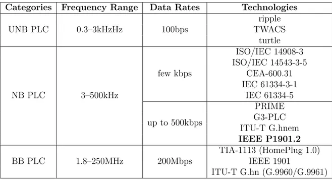
PLC can be classified in three categories [GSW10] depending on the frequency range:
1. Ultra Narrow Band (UNB) PLC: Ultra Low Frequency (0.3-3kHz) band or in the upper part of the Super Low Frequency (30-300 Hz) band;
2. Narrowband (NB) PLC: Very Low Frequency/Low Frequency /Medium Fre-quency bands: (3–500kHz);
3. Broadband (BB) PLC: lower frequencies (1.8–250MHz): High Frequency/Very High Frequency bands (1.8-250 MHz).
UNB band operates in the 0.3–3kHz band. While throughput can be considered as low (around 100bps), long distances can be crossed (over 150 km) with UNB PLC. Examples of UNB PLC utilizations are ripple carrier signaling, turtle system and more recently Two-Way Automatic Communication System (TWACS). It has to be noted that at the present time, no standard is existing for UNB PLC and that the aforementioned examples are proprietary solutions.
NB PLC operates in the frequency range from 3 kHz to 500 kHz (Figure 1.3), in-cluding the EuropeanCommittee for Electrotechnical Standardization (CENELEC) bands (3–148.5 kHz), the US Federal Communications Commission (FCC) band (10–490 kHz), the JapaneseAssociation of Radio Industries and Businesses (ARIB) band (10–450 kHz) and the Chinese band (3–500 kHz). NB PLC offers range up to several kilometers and data rate up to 500kbps. [GSW10] proposed a classification for NB PLC:
• Low data rate (LDR): provides throughput of few kbps based on single carrier technology. A wide variety of standards exists such asISO/IEC 14908-3
(Lon-Works), ISO/IEC 14543-3-5 (KNX), CEA-600.31 (CEBus), IEC 61334-3-1, IEC 61334-5 (FSK and Spread-FSK);
Fre-CHAPTER 2. IEEE P1901.2: A NARROWBAND PLC PROTOCOL FOR THE SMART GRID
2
Categories Frequency Range Data Rates Technologies
UNB PLC 0.3–3kHzHz 100bps ripple TWACS turtle NB PLC 3–500kHz few kbps ISO/IEC 14908-3 ISO/IEC 14543-3-5 CEA-600.31 IEC 61334-3-1 IEC 61334-5 up to 500kbps PRIME G3-PLC ITU-T G.hnem IEEE P1901.2 BB PLC 1.8–250MHz 200Mbps TIA-1113 (HomePlug 1.0) IEEE 1901 ITU-T G.hn (G.9960/G.9961) Table 2.2: PLC classification.
quency Division Multiplexing (OFDM), capable of data rates ranging between tens of kbps and up to 500 kbps. Typical examples of HDR NB PLC tech-nologies are G3-PLC, ITU-T G.hnem, and IEEE P1901.2.
BB PLC (operating in the 1.8–250MHz) frequency range allows high data rates
(up to 200Mbps). TIA-1113 (HomePlug 1.0), IEEE 1901, and ITU-T G.hn (G.9960/G.9961) are examples of BB PLC technologies.
Table 2.2 summarizes characteristics of UNB, NB, and BB PLC technologies.
2.2.3 AMI traffic pattern
In order to choose an adequate PLC solution for AMI, traffic patterns needs to be characterized. [draa] defines traffic pattern requirements in AMI environment in two classes:
• From the utility Head-End server to SMs: Head-End-to-Meter (HE2M) traffic; • From SMs to the Head-End server: Meter-to-Head-End (M2HE) traffic. The notion of Head-End server refers to any server operated by the utilities and that is located in the WAN. Head-end server sends traffic for:
• SM configuration: a configuration change (e.g., change the schedule of SMs periodic energy consumption report) as well as firmware update;
2
2.3. IEEE P1901.2
SMs generate scheduled traffic (e.g., periodic meter reads), event-based traffic (e.g. power outage) or based on on-demand requests (e.g., meter read requested by Head-end server).
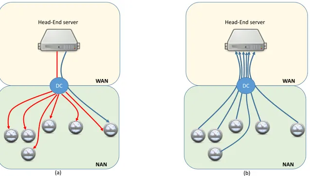
Figure 2.3 depicts M2HE and HE2M traffic in AMI infrastructure.
NAN WAN Head-End server DC NAN WAN Head-End server DC (a) (b)
Figure 2.3: Traffic Pattern inside AMI. (a) stands for HE2M traffic and (b) for M2HE traffic pattern. Blue arrow represents unicast traffic while red one represents multicast traffic.
Head-end server can either reach a specific SM directly in a unicast way (
Point-to-Point (P2P)) or can reach a group of devices by using multicast (Point-to-Multipoint (P2MP) while SMs usually send traffic to a specific head-end server in
an unicast way and generate Multipoint-to-Point (MP2P) traffic.
2.3 IEEE P1901.2
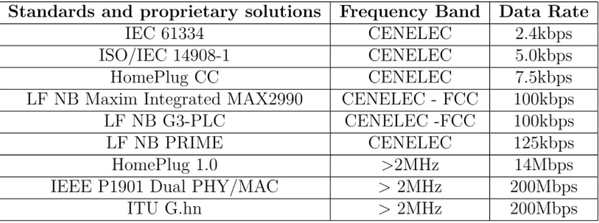
In 2009, Institute of Electrical and Electronics Engineers (IEEE) decided to create the working group P1901.2 to standardize a Low Frequency Narrowband (LF NB) (<500 kHz) PLC solution. Indeed, at that time, no standard was existing for such kind of technology as shown on Table 2.3.
The IEEE P1901.2 [IEE10] standard is designed for indoor and outdoor elec-trical wiring Power Line Communication (PLC) over low voltage (<1000V) and medium voltage (1000V to 72kV). The standard employs techniques and mecha-nisms defined in two related standards covering the same scope, namely: G3-PLC
CHAPTER 2. IEEE P1901.2: A NARROWBAND PLC PROTOCOL FOR THE SMART GRID
2
Standards and proprietary solutions Frequency Band Data Rate
IEC 61334 CENELEC 2.4kbps
ISO/IEC 14908-1 CENELEC 5.0kbps
HomePlug CC CENELEC 7.5kbps
LF NB Maxim Integrated MAX2990 CENELEC - FCC 100kbps
LF NB G3-PLC CENELEC -FCC 100kbps
LF NB PRIME CENELEC 125kbps
HomePlug 1.0 >2MHz 14Mbps
IEEE P1901 Dual PHY/MAC > 2MHz 200Mbps
ITU G.hn > 2MHz 200Mbps
Table 2.3: Existing PLC standards and proprietary solutions in 2009 for Low and High Data Rate PLC.
P1901.2 can operate in three different bands to overcome global regulations problem: the Committee for Electrotechnical Standardization (CENELEC) band in Europe (CENELEC bands A, B, C, and D), which has an upper limit of approximately 150kHz; the Association of Radio Industries and Businesses (ARIB) band (Japan), which has an upper limit of approximately 450kHz; and the Federal
Communica-tions Commission (FCC) band (multiple countries), which has an upper limit of
approximately 500kHz. In this thesis, we focus on IEEE P1901.2 standard in the CENELEC A band as it is the spectrum reserved for power companies in Europe.
The physical characteristics of Narrowband (NB) PLC resembles the ones of low-power, lossy radio links. As a consequence, IEEE P1901.2 reuses parts of the
Medium Access (MAC) layer and channel access methods of IEEE 802.15.4 [GCB03].
However, as IEEE P1901.2 uses several modulations, aPhysical (PHY) layer header was added to specify parameters relative to the payload.
2.3.1 Physical layer
IEEE P1901.2 usesOrthogonal frequency-division multiplexing (OFDM) and sup-ports two different modulation schemes:
• Differential mode (mandatory) modulations: Differential Binary Phase Shift
Keying (DBPSK), Differential Quaternary Phase Shift Keying (DQPSK),
and Differential Eight Phase Shift Keying (D8PSK);
• Coherent mode (optional) modulations: BPSK, QPSK, 8PSK, and 16QAM. It has to be noted that both modes share a default robust modulation: Robust
Orthogonal Frequency Division Multiplexing (ROBO).
We decided to focus on the mandatory mode in that thesis. IEEE P1901.2 CENELEC A band works specifically in the 35kHz–91kHz band range [IEE10] and
2
2.3. IEEE P1901.2
uses OFDM modulation over 36 carriers.
Figure 2.4: IEEE P1901.2 frame structure.
The PHY layer supports two type of frames: data and ACK/NACK. Frame structure is shown in Figure 2.4. Each frame starts with a preamble, followed
by the Frame Control Header (FCH). ACK/NACK frames are only made of
Preamble+FCH while data frames are followed by the data itself.
The preamble is used for synchronization, channel estimation and initial phase reference estimation. The FCH includes information such as the type of frame, its length, modulation and Tone-Map mechanism described in Section 2.3.3.
2.3.2 MAC layer
The MAC layer frame follows the FCH and is based on the IEEE 802.15.4 with almost identical structure. It has to be noted that IEEE P1901.2 does not use classical IEEE 802.15.4 MAC acknowledgment frames to confirm unicast frames. Instead, it specifies positive and negative acknowledgments in the FCH as explained above. Thus, IEEE P1901.2 acknowledgments can be seen as PHY ACK.
2.3.2.1 Channel access
Channel access is performed thanks to Carrier Sense Multiple Access with
Col-lision Avoidance (CSMA/CA) with a random backoff time. The random backoff
mechanism is used to spread the time over which stations attempt to transmit in order to reduce the probability of collisions. Each time a device wishes to transmit data frames, it waits for a random period. If the channel is idle after that period, the device is able to transmit its data frame. If the channel is busy after the random backoff time, the device has to wait an other random period before to access the channel again. In order to detect channel occupancy,Physical Carrier Sense (PCS) is used.
IEEE P1901.2 defined two CSMA/CA modes: an unslotted version for the manda-tory non-beacon PAN described in IEEE 802.15.4-2006 and a slotted version for the optional beacon-enabled PAN.
CHAPTER 2. IEEE P1901.2: A NARROWBAND PLC PROTOCOL FOR THE SMART GRID
2
We decided to investigate the mandatory mode i.e the unslotted CSMA/CAmode. This mode ressembles to the IEEE 802.15.4 CSMA/CA but it is modified in order to take into acccount priority and fairness in order to improve efficiency. The algorithm implementation used unit of time calledbackoff periods. Each device maintains four variables for each transmission attempt:
• NB: the number of times the CSMA/CA algorithm was required to backoff while attempting the current transmission.
• NBF: count of backoff attempts and it is used to control channel access fair-ness.
• minCWCount: the number of time minimum contention window value was used to set backoff time.
• CW : contention window for each device. On device startup, the CW is ini-tialized to 2macMinBE. The device updates the CW based on channel access success or failure:
– For every channel access failure, the CW value doubles. The maximum
value of CW is bounded by 2macMaxBE
– Upon a successful transmission, the CW value is adjusted using the
for-mula CW [next] = max(CW [prev] − A ∗ (2macM inBE, 2macM inBE) Figure 2.5 depicts in detail the steps of CSMA/CA algorithm. The main differ-ences compared to IEEE 802.15.4 CSMA/CA mechanism occur inStep 3 and Step 7 that allow better fairness between devices;Step 3 ensures fairness by comparing the number of time minimum contention windows (minCW ) was used with the constant
maxMinCWAttempts. If minCW is greater than maxMinCWAttempts, the CW is
set to the maximum value 2macMaxBE. Thus, it avoids the same device to always use the minimum contention window and then, helps other station to have access to the medium; Step 7 is triggered when the channel was not found idle after the backoff timer. At that time, if the number of backoff attemps NBF is greater than the constant; macCSMAFairnessLimit and if NBF is multiple of K (Fairness Rate Adaptation Factor), the device is going to act as if the transmission was success-ful i.e. the CW is linearly decreased to allow for higher chance for pending frame transmission to succeed for devices which did not get the opportunity to transmit.
2.3.2.2 Inter Frame Spacing (IFS)
Due to propagation and processing time, a time interval is needed between frames: the Inter Frame Spacing (IFS). Figure 2.6 shows the different existing IFS:
• Contention Interframe Space (CIFS): used after the end of the previous trans-mission.
• Response Interframe Space (RIFS): the time between the end of a transmis-sion and the start of its associated response. If no response is expected, the CIFS is in effect.
2
2.4. CONCLUSION
• Extended Interframe Space (EIFS): used when the station does not have complete knowledge of the state of the medium. This can occur when the station initially attaches to the network, when errors in the received frames make them impossible to decode unambiguously, or in the case a transmitter does not receive an ACK frame after a transmission for which the receiver was expected to issue an ACK to that transmitter. If a packet is received and correctly decoded before the expiration of the EIFS, then the EIFS is canceled.
2.3.3 Tone-Map mechanism
IEEE P1901.2 can use up to 4 modulations in mandatory mode: ROBO, DBPSK, DQPSK, and D8PSK. Additionally, IEEE P1901.2 works with 36 carriers (grouped in 6 sub-bands of 6 tones) in CENELEC A band, each sub-bands being usable depending on channel conditions. Thus, it renders the problem of selecting a path between two nodes non-trivial, as the possible number of combinations increases significantly, e.g. use a direct link with slow robust modulation, or use a relay meter with fast modulation and 2 disabled sub-bands. To overcome that problem, IEEE P1901.2 technology offers a mechanism for periodic exchanges on the link quality between nodes to constantly react to channel fluctuations – the adaptive
Tone-Map (TM) mechanism. Every meter keeps a state of the quality of the link
to each of its neighbors with whom it is communicating thanks to TM mechanism. When a device does not know the modulation to use for a particular neighbor, it must send the frame using ROBO mode and setting theTone-Map Request (TMReq) bit in the FCH. Upon receiving a frame with the TMReq bit set, the receiver is going to estimate thanks to PHY preamble the communication link between the sender and the receiver and to choose the PHY parameters to use on this link. After the estimation, the receiver is going to generate a Tone-Map Response (TMResp) message. This frame contains the modulation to use, as well as the group of tones (i.e. sub-band) to use from frame transmission. It has to be noted that ROBO modulation must transmit using all the sub-bands.
2.4 C
ONCLUSION
In this chapter, we presented the big picture of the architecture used in this thesis: the Smart Grid (SG) and the Advanced Metering Infrastructure (AMI). We also made an overview of the existing PLC techniques and we presented one NB PLC technology that fits for AMI: IEEE P1901.2. Next Chapter will introduce RPL routing protocol main characteristics, as well as two other candidate routing protocols: LOAD and LOADng.
CHAPTER 2. IEEE P1901.2: A NARROWBAND PLC PROTOCOL FOR THE SMART GRID
2
2
2.4. CONCLUSION
3
Routing Protocols
In the previous chapter, we highlighted that PLC characteristics lead to thedevelopment of new standardized solutions. In this chapter, we introduce a classi-fication of routing protocols and more particularly, what lead to the design of new solutions specially tailored to Low power and Lossy Networks (LLNs). We present three routing protocols for LLN: RPL: IPv6 Routing Protocol for Low-Power and
Lossy Networks (RPL), 6LoWPAN Ad Hoc On-Demand Distance Vector Rout-ing (LOAD) and Lightweight On-demand Ad hoc Distance-vector RoutRout-ing Protocol Next Generation (LOADng).
Section 3.1 presents the usual classification used for routing protocols (i.e. proac-tive or reacproac-tive) before to detail the need for new routing protocols specially designed for Low power and Lossy Network (LLN). Section 3.2 introduces two reactive rout-ing protocols: LOAD and LOADng while Section 3.3 presents in detail the proactive protocol used in that thesis: RPL routing protocol.
3.1 R
OUTING PROTOCOLS
In a Narrowband (NB) Power Line Communication (PLC) IEEE P1901.2 in-frastructure, it is impossible for most of the nodes to communicate directly due to various reasons: distance, noises, etc. Thus, each node must collaborate by relaying frames in order to be able to reach all nodes in the network. Routing protocols are designed to select, construct and maintain best paths in the network in order to route packets from source to destination. Traditionally, routing protocols are divided into two categories based on the way routing information is propagated namely: proactive and reactive protocols.
3.1.1 Reactive Protocols
Reactive protocols work by building routes on demand way and maintaining them only if needed. The main advantage compared to the proactive approach is that there is no need to maintain a route when there is no traffic and thus to be less greedy in term of resources. However, as the route does not exist before to its use,

![Figure 1.3: Regulatory frequency map. (source:[IEE10])](https://thumb-eu.123doks.com/thumbv2/123doknet/11371679.286075/32.892.192.749.168.484/figure-regulatory-frequency-map-source-iee.webp)

![Figure 2.5: CSMA/CA unslotted mechanism. ( source: [IEE10] )](https://thumb-eu.123doks.com/thumbv2/123doknet/11371679.286075/47.892.161.693.253.981/figure-csma-ca-unslotted-mechanism-source-iee.webp)
![Figure 2.6: Inter Frame Spacing for IEEE P1901.2. ( source: [IEE10] )](https://thumb-eu.123doks.com/thumbv2/123doknet/11371679.286075/48.892.218.720.454.782/figure-inter-frame-spacing-ieee-p-source-iee.webp)
