HAL Id: hal-01108754
https://hal.archives-ouvertes.fr/hal-01108754
Submitted on 26 May 2015
HAL is a multi-disciplinary open access
archive for the deposit and dissemination of
sci-entific research documents, whether they are
pub-lished or not. The documents may come from
teaching and research institutions in France or
abroad, or from public or private research centers.
L’archive ouverte pluridisciplinaire HAL, est
destinée au dépôt et à la diffusion de documents
scientifiques de niveau recherche, publiés ou non,
émanant des établissements d’enseignement et de
recherche français ou étrangers, des laboratoires
publics ou privés.
Metamaterial-Inspired Monopole Antenna
Saber Dakhli, Hatem Rmili, Kourosh Mahdjoubi, Jean Marie Floc’H, Fethi
Choubani
To cite this version:
Saber Dakhli, Hatem Rmili, Kourosh Mahdjoubi, Jean Marie Floc’H, Fethi Choubani.
Anal-ysis of a Compact and Superdirective Metamaterial-Inspired Monopole Antenna.
International
Journal of Antennas and Propagation, Hindawi Publishing Corporation, 2014, 2014, pp.806379.
�10.1155/2014/806379�. �hal-01108754�
Research Article
Analysis of a Compact and Superdirective Metamaterial-Inspired
Monopole Antenna
Saber Dakhli,
1,2Hatem Rmili,
3Kourosh Mahdjoubi,
4Jean-Marie Floc’h,
2and Fethi Choubani
11Innov’Com Laboratory, SUPCOM, University of Carthage, 2083 Tunis, Tunisia
2IETR, University of Rennes 1, Campus Beaulieu, Bˆat. 11D, No. 263, Avenue G´en´eral Leclerc, CS 74205, 35042 Rennes Cedex, France 3Electrical and Computer Engineering Department, King Abdulaziz University, P.O. Box 80204, Jeddah 21589, Saudi Arabia 4IETR, INSA, 20 Avenue Buttes des Co¨esmes, 35043 Rennes, France
Correspondence should be addressed to Hatem Rmili; hmrmili@kau.edu.sa
Received 15 March 2014; Revised 27 July 2014; Accepted 18 August 2014; Published 28 October 2014 Academic Editor: Zhi N. Chen
Copyright © 2014 Saber Dakhli et al. This is an open access article distributed under the Creative Commons Attribution License, which permits unrestricted use, distribution, and reproduction in any medium, provided the original work is properly cited.
The directivity of a metamaterial-inspired compact (0.145𝜆0) monopole antenna was investigated. The proposed structure is
composed of a split-ring resonator (SRR) parasitic element placed in the vicinity of a monopole antenna. Two configurations denoted by A1 and A2 were considered depending on the position of the slot in the SRR element. By analyzing simulated and measured results, the superdirectivity (7.5 dBi for A1 and 9 dBi for A2) of the structure was discussed. It is found that the monopole-SRR and/or ground plane-monopole-SRR coupling effects may be responsible for the superdirectivity of the structure.
1. Introduction
The design of compact antennas is a topic of considerable interest within the antenna community. For this reason,
var-ious miniaturization techniques [1–3] have been developed
such as load of lumped elements (inductive and capacitive), use of passive and active matching circuits, new materials and composites, and metamaterials.
Recently, a new design approach based on the use of metamaterial-inspired constructs has been emerged and applied in order to improve the radiation properties of
antennas [4].
Since 2007, an efficient and electrically small antenna system operating at multifrequency bands was proposed by Erentok and Ziolkowski for new generation communication
systems [5]. Next, this new concept was applied to design
antennas with improved performances such as
miniaturiza-tion [6–9], high efficiency [10–12], enhanced bandwidth [13,
14], high gain [15,16], and reconfigurability [17–19].
For example, a new technique inspired from a metama-terial has been proposed for the design of an ultracompact
printed antenna (size around 0.178𝜆0) for WLAN
applica-tions [8]. In [13], a metamaterial-inspired loading was used
for the design of a compact printed dipole antenna (0.294𝜆0
× 0.075𝜆0) with enhanced bandwidth of 56%.
The frequency reconfigurability of compact (0.056𝜆0×
0.047𝜆0) metamaterial-inspired antennas was also
investi-gated in [17], where the operating frequency of a printed
monopole with incorporated slot and varactor diode was tuned over the broad frequency range 1.6–2.23 GHz. High efficiency (between 80 and 91%), in addition to radiation patterns reconfigurability, was also obtained for metamaterial
inspired compact monoband antennas [18].
However, the radiation properties of miniature antennas
which are highly dependent on the antenna size [20,21] are
usually studied in terms of gain, efficiency, and radiation quality factor and rarely with a directivity point of view. For this reason, we focus our study in this paper on the investiga-tion of the directivity of a compact monopole metamaterial-inspired antenna.
Recently, few works were interested in the
superdirectiv-ity of metamaterial-inspired compact antennas [22–27]. The
Volume 2014, Article ID 806379, 10 pages http://dx.doi.org/10.1155/2014/806379
main techniques used to realize superdirective antennas were
resumed recently in [22]. These techniques are dealing with
the use of high-impedance surface [23], Huygens sources
[24,25], lumped elements [26], and electrically small arrays
[27].
In fact, the term of superdirectivity was used by Taylor in
1948 [28], with reference to the work of Riblet dealing with
the maximum directivity of antennas [29].
In 1958, Harrington [30] proposed a limit for the
max-imum directivity 𝐷 of an antenna in a specific direction
(𝜃0, 𝜑0) by taking𝑁 modes responsible for the radiation of
the structure:
𝐷max(𝜃0, 𝜑0) = 𝑁2+ 2𝑁. (1)
Harrington used the asymptotic expansion of Hankel’s func-tions to establish a relafunc-tionship between the number of modes 𝑁 and the antenna size 𝑘𝑎:
𝑘𝑎 ≈ 𝑁. (2)
𝑘 is the wave number, and 𝑎 is the radius of the smallest sphere enclosing the antenna.
By combining (1) and (2), we obtain
𝐷max≈ (𝑘𝑎)2+ 2 (𝑘𝑎) . (3)
With this expression, Harrington proposed the first limit of the directivity versus the antenna size. When the directivity is
greater than𝐷max, the antenna is considered superdirective.
In this paper, we focus our study on the use of the Huygens source technique in order to improve the compact-ness and directivity of a monopole metamaterial-inspired antenna.
In a previous work [12], we have studied a family
of efficient metamaterial-inspired antennas composed of a monopole antenna with a split-ring resonator (SRR) parasitic element. Four configurations of the antenna were studied by changing the position of the slot in the SRR loop. It has been shown that, among the four studied configurations, only two of them exhibit a high directivity.
In this work, we propose a deep study in order to analyze the superdirectivity behavior of the two previous con-figurations of the metamaterial-inspired compact antenna. The antenna consists of a split-ring resonator (SRR) cell placed in the near-field region of a monopole antenna in order to reduce the profile of the structure and to reach
the superdirectivity(𝐷 > 𝐷max). A detailed study will be
presented in order to determine the origin of the obtained superdirectivity for the proposed structure.
This paper is arranged as follows. InSection 2, details on
the structure design are presented.Section 3presents both
numerical analysis of the structure and its experimental
vali-dation. Finally,Section 4gives the main concluded results.
2. Antennas Design
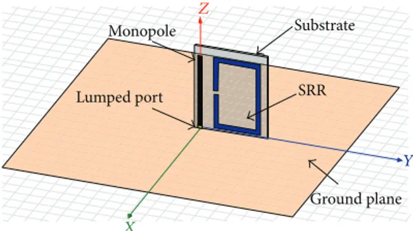
The structure of the proposed antenna is shown inFigure 1.
The antenna is composed of two elements (SRR and monopole) which are printed on a dielectric substrate and
Monopole Lumped port Ground plane Substrate SRR Z X Y
Figure 1: HFSS model for the antenna with configuration A1.
mounted orthogonally on a rectangular ground plane. The
considered substrate is Rogers Duroid 5880 of thicknessℎ =
0.8 mm and relative permittivity 𝜀𝑟 = 2.2, and the dimensions
of the ground plane are100 × 100 mm2.
The printed monopole of length 𝐿𝑀and width𝑊𝑀 is
coupled electromagnetically to the rectangular SRR element
of dimensions𝐿𝑅× 𝑊𝑅, width𝑡, and gap 𝑊𝑔. The coupling
distance between the monopole and the resonator is denoted
by𝑑1, whereas the distance separating the ground plane to
the lower edge of the SRR is𝑑2. The monopole is designed
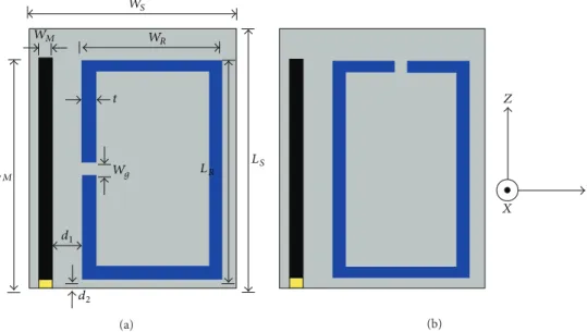
to operate at 2.45 GHz. Two configurations were considered depending on the location of the SRR-slot as shown in
Figure 2. Details on the parameters design are given in
Figure 2(a)andTable 1.
The antenna excitation is ensured by the monopole, which is soldered to the feeding coaxial cable via an sma connector, whereas the SRR acts as a parasitic element. At lower frequency, the monopole acts as a capacitive element and the SRR acts as an inductive one. The presence of the SRR element close to the monopole provides a reactance compensation and consequently we obtain a new resonant frequency lower than the monopole one, which allows the miniaturization of the structure.
3. Results and Discussion
The main simulated and measured results of the antenna with its two configurations were presented and discussed in this section, where analysis of the gain, directivity, surface current distribution, and the shape of radiation patterns were done in order to explain the origin of the antenna superdirectivity. 3.1. Simulation. The simulated return loss of the antenna with
its two configurations A1 and A2 is plotted inFigure 3.
We can notice that the proposed structure presents a dual-band frequency for both configurations A1 and A2. The
higher resonant frequency𝐹𝑀 = 2.45 GHz corresponds to
the monopole and seems to be unaffected by the presence of the loop resonator.
The lower resonant frequency appears when we add the SRR element in the vicinity of the monopole. This resonance shifts toward low frequencies due to the effect of the parasitic
element (𝐹𝑅1 = 1.55 GHz for A1; 𝐹𝑅2 = 1.75 GHz for A2),
LS LR t d1 d2 LM Wg WS WM WR (a) Z Y X (b)
Figure 2: Geometry of the antenna: (a) configuration A1, (b) configuration A2.
Ret u rn loss (dB) Configuration A1 Configuration A2 1 0 1.5 2 2.5 3 Frequency (GHz) −25 −20 −15 −10 −5
Figure 3: Simulated return loss of the proposed antennas.
However, both resonant frequencies seem to be slightly dependent on the SRR-slot position; a frequency shift of 200 MHz can be noticed between configurations A1 and A2.
We can deduce fromFigure 3that configuration A1 offers
more compactness for the structure and better impedance matching at the two operating frequencies than A2.
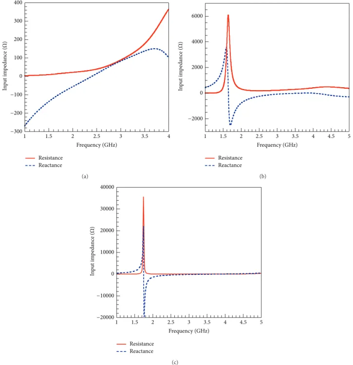
According to Figure 4(a), when the frequency 𝐹 <
𝐹𝑀, the imaginary part of the input impedance is
nega-tive; the monopole acts then as a capacitive element in
this frequency range. However, when the frequency 𝐹 <
𝐹𝑅, the imaginary part of the input impedance is positive
(Figures4(b)and4(c)) and the SRR acts as an inductive
element.
Table 1: Parameters design. Dimensions in mm Parameters Values 𝐿𝑆 28 𝑊𝑆 24 𝐿𝑀 26.5 𝑊𝑀 1.5 𝐿𝑅 25.5 𝑊𝑅 17 𝑡 1.5 𝑊𝑔 1.5 𝑑1 5 𝑑2 1
Consequently, the effect of the monopole is compensated by the SRR, and the input impedance of the structure
is achieved at the lower resonance frequency 𝐹𝑅, which
improves the compactness of the structure.
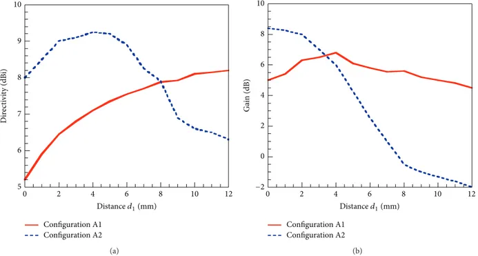
During the numerical analysis and parametric optimiza-tion of the antenna, we have found that the main parameter that may affect the antenna radiation is the coupling distance between the monopole and the RSS element. We have studied then the directivity and the gain as a function of the
distance𝑑1 between the monopole and the SRR for the two
configurations of the antenna (Figure 5).
We can notice first fromFigure 5that both of the
direc-tivity and the gain of the structure depend on the coupling distance between the resonator and the monopole.
According toFigure 5(a), the maximum simulated
direc-tivities are 8.2 dBi and 9.2 dBi for configurations A1 and A2, respectively. We should note here that these values
were obtained for coupling distances 𝑑1 = 20 mm for A1
and 𝑑1 = 4 mm for A2, where the antenna is not well
0 100 200 300 400 1 1.5 2 2.5 3 3.5 4 Frequency (GHz) Resistance Reactance −200 −100 −300 In p u t im p eda nce ( Ω ) (a) 0 2000 4000 6000 1 1.5 2 2.5 3 3.5 4 4.5 5 Frequency (GHz) −2000 In p u t im p eda nce ( Ω ) Resistance Reactance (b) 0 10000 20000 30000 40000 1 1.5 2 2.5 3 3.5 4 4.5 5 Frequency (GHz) −20000 −10000 In p u t im p eda nce ( Ω ) Resistance Reactance (c)
Figure 4: Simulated complex input impedance of the (a) monopole alone; (b) SRR alone (configuration A1); (c) SRR alone (configuration A2).
for coupling distances equal to 4 mm and 5 mm for A1 and A2, respectively. However at these distances the maximum directivity drops to 4.41 dBi for both configurations.
For the simulated gain, we can notice fromFigure 5(b)
that the maximum values are about 9 dBi and 7 dBi, for A1 and A2, respectively. These values were also obtained for coupling distances d1 different from those optimized for the best impedance matching. We can also remark that the gain is more stable for configuration A2 than A1 over the coupling distance range 1–12 mm.
InFigure 6, we have considered the chart established in
[22] to classify the antenna directivity versus the size of three
antennas reported in the literature, and we have placed our simulated maximum values obtained for configurations A1
and A2. Harrington’s limit was calculated by considering (3).
Since the radius of the sphere enclosing the structure is 𝑎 = 20 mm for configuration A1 and 𝑎 = 22.6 mm for A2, at
the lowest resonance frequencies𝐹1𝑅 = 1.55 GHz and 𝐹2𝑅=
1.75 GHz, respectively, then ka∼0.65 and 2𝑎/𝜆 = 0.20 for A1, while ka∼0.78 and 2𝑎/𝜆 = 0.24 for A2. The corresponding
5 6 7 8 9 10 0 2 4 6 8 10 12 Configuration A1 Configuration A2 Dir ec ti vi ty (dB i) Distance d1(mm) (a) 0 2 4 6 8 10 Ga in (dB) 0 2 4 6 8 10 12 Configuration A1 Configuration A2 Distance d1(mm) −2 (b)
Figure 5: Effect of the coupling distance𝑑1at the frequency𝐹𝑅, on the simulated directivity (a) and gain (b), for configurations A1 (𝐹𝑅 =
1.55 GHz) and A2 (𝐹𝑅= 1.75 GHz). 2a/𝜆 Dipole 𝜆/2 0 2 4 6 8 10 12 14 16 0 0.2 0.4 0.6 0.8 1 Dir ec ti vi ty (dB i) Harrington’s limit ESA antennas [20] A2 A1 [23] [16] [25][24] [26]
Figure 6: Position of simulated maximum directivities of the structure with its two configurations A1 and A2 in the chart representing the directivity versus the antenna size.
values of the directivity (4.41 dBi for A1 and 5.5 dBi for
A2) are placed in the chart ofFigure 6. These values which
are calculated from the maximum directivities presented in Figure 5(a) by subtracting 3 dBi (in order to remove the effect of the ground plane) are situated in the region characterizing ESA antennas above Harrington’s directivity limit. Consequently, both configurations A1 and A2 of the
studied structure are situated in the first zone of the chart dedicated to small antennas and above Harrington’s limit, which means that the proposed structure can be considered as a superdirective and compact antenna.
The superdirectivity of the antenna may be attributed to the constructive interference between radiated fields from both the monopole and the resonator; these fields should be in phase or phase-opposition and with the same order of magnitude to obtain the highest directivity.
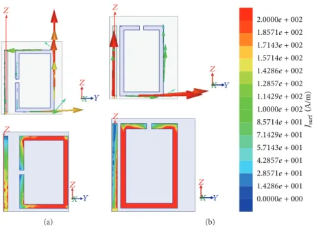
By analyzing the current distribution for configuration A1 (Figure 7(a)) at the lower operating frequency𝐹𝑅and for
the optimized coupling distance𝑑1, we can remark that the
current vectors on the horizontal arms of the SRR element are weak and opposite which leads to their compensation. In addition, these currents are orthogonal to the monopole’s current, which may lead to a destructive superposition between radiated fields from the monopole and the resonator. However, the current vector on the monopole is high and concentrated only on the right vertical arm of the SRR. This current vector is parallel and opposite to the monopole’s current (phase-opposition), which leads to a constructive superposition between radiated fields and then increases of the antenna directivity.
For configuration A2 (Figure 7(b)), in addition to the
vertical SRR current which, as for configuration A1, is parallel to the monopole’s current and may explain the increase of directivity, the horizontal SRR current is localized only on the inferior arm of the resonator, close to the ground plane. This high coupling SRR-ground plane may explain the further increase of the directivity of configuration A2 compared to A1.
Z Z Z Y X Z Y X (a) Z Z Z Y X Z Y X Jsur f (A/m) 2.0000e + 002 1.8571e + 002 1.7143e + 002 1.5714e + 002 1.4286e + 002 1.2857e + 002 1.1429e + 002 1.0000e + 002 8.5714e + 001 7.1429e + 001 5.7143e + 001 4.2857e + 001 2.8571e + 001 1.4286e + 001 0.0000e + 000 (b)
Figure 7: Simulated vector (up) and scalar (down) currents on the monopole and the SRR at the operating frequency𝐹𝑅and for the coupling
distance𝑑1: (a) configuration A1 (𝐹𝑅= 1.55 GHz, 𝑑1= 4 mm); (b) configuration A2 (𝐹𝑅= 1.75 GHz, 𝑑1= 1 mm).
In order to confirm our hypothesis, we have plotted in
Figure 8the current magnitude on both the monopole and the SRR element for different coupling distances.
According toFigure 7(a)dealing with configuration A1,
the current magnitudes on the monopole and the SRR are
similar (for𝑑1= 4 mm, 𝐽𝑠∼2.2⋅102A/m) for configuration A1,
while, for configuration A2 (Figure 7(b)), they are different
(for 𝑑1 = 4 mm, 𝐽𝑠∼ 1.6 ⋅ 102A/m for the monopole and
𝐽𝑠∼ 3.4 ⋅ 102A/m for the SRR). We should note here that
by considering coupling distance values slightly superior (5
or 6 mm) to the considered value𝑑1 = 4 mm, which gives
also high directivities as shown inFigure 5, the discrepancy
between the monopole and SRR currents is clearly reduced.
For configuration A2 (Figure 7(b)), although, for the
coupling distance 𝑑1 = 1 mm, the currents on both the
monopole and the SRR are different, the effect of the
SRR-ground plane coupling (𝑑2 = 1 mm) seems to be so high
to compensate first for the low monopole-SRR coupling and then to improve the total directivity of the structure.
The simulated 3D-radiation patterns of the structure,
with a ground plane of dimension 100 × 100 mm2, are
given in Figure 9. These patterns correspond to resonant
frequencies 1,55 GHz and 1,75 GHz, for configurations A1
and A2, respectively. We can notice fromFigure 9 that the
effect of the SRR-slot location on the radiation pattern is not significant.
In addition, the shape of the radiation pattern may be explained by a superposition of two patterns corresponding
to an electric dipole (along𝑧-axis) and a magnetic dipole
(placed orthogonally to 𝑥-axis). This assumption, verified
from simulation of the SRR and the monopole separately, may
explain the absence of the radiation null along𝑧-axis for the
structure.
Then, we can suppose that the structure behaves as a Huy-gens source, where the SRR element acts as a magnetic dipole
and the monopole as electric dipole, which may explain the antenna superdirectivity. The ground plane contributes also to reflect the radiated power from the antenna toward the upper half-plane (𝑧 > 0), which increases further the directivity.
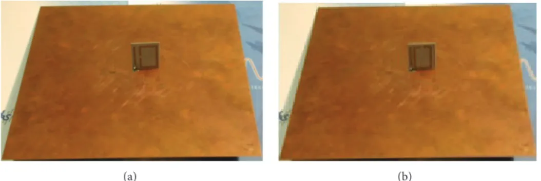
3.2. Experimental Validation. The two prototypes of the structure corresponding to configurations A1 and A2 (see
Figure 10) were realized and characterized by measuring their impedance matching, radiation patterns, and directivity. The return losses were measured over the frequency range 1–3 GHz by using an Agilent-N5230A network analyzer, whereas the radiation patterns and directivity measurements were carried out in the anechoic chamber “SATIMO Star-gate32” situated at the IETR Institute.
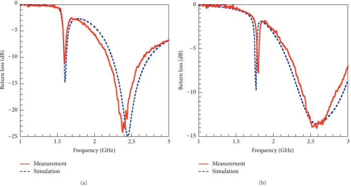
The measured return losses of the designed antenna for
configurations A1 and A2 are given inFigure 11. We can notice
from this figure a good agreement between simulation and measurement with a small discrepancy due to fabrication errors.
As shown inFigure 11, the proposed antenna presents a
dual-band behaviour. The main operating frequency of the
structure is the lowest one. Then, this resonant frequency𝐹𝑅is
equal to 1.55 GHz for A1 and 1.75 GHz for A2. The impedance matching of the structure can be better improved by adjusting
the distance𝑑2 separating the SRR element from the finite
ground plane.
Table 2resumes simulated and measured overall efficien-cies (OE) for the two proposed antennas at both lower and higher operating frequencies. The overall efficiency OE is
defined as the ratio of the radiated power𝑃radto the input
power𝑃in[31]:
OE= 𝑃rad
𝑃in
0 1 2 3 4 5 6 7 8 4 8 12 16 20 24 28 SRR Monopole M axim um c u rr en t Js (10 2 A/m) Distance d1(mm) (a) 0 1 2 3 4 5 6 7 4 8 12 16 20 SRR Monopole M axim um c u rr en t Js (10 2A/m) Distance d1(mm) (b)
Figure 8: Maximum current𝐽𝑆(A/m), at the operating frequency𝐹𝑅, on the monopole, and the SRR versus the coupling distance𝑑1: (a)
configuration A1 (𝐹𝑅= 1.55 GHz), (b) configuration A2 (𝐹𝑅= 1.75 GHz). 1.8065e + 000 9.1223e − 001 1.7971e − 002 −8.7629e − 001 −1.7706e + 000 −2.6648e + 000 −3.5591e + 000 −4.4533e + 000 −5.3476e + 000 −6.2419e + 000 −7.1361e + 000 −8.0304e + 000 −8.9246e + 000 −9.8189e + 000 −1.0713e + 001 −1.1607e + 001 −1.2502e + 001 Z Y X Phi DirT o tal (dB) Z Y X Phi Theta (a) 2.5347e + 000 1.5541e + 000 5.7358e − 001 −4.0698e − 001 −1.3875e + 000 −2.3681e + 000 −3.3486e + 000 −4.3292e + 000 −5.3097e + 000 −6.2903e + 000 −7.2709e + 000 −8.2514e + 000 −9.2320e + 000 −1.0213e + 001 −1.1193e + 001 −1.2174e + 001 Z Y X Theta Phi −1.3154e + 001 DirT o tal (dB) Z Y X Theta Phi (b)
Figure 9: Simulated 3D-radiation patterns for the structure: (a) configuration A1 (𝐹𝑅= 1.55 GHz), (b) configuration A2 (𝐹𝑅= 1.75 GHz).
(a) (b)
1 1.5 2 2.5 3 Measurement Simulation Ret u rn loss (dB) 0 Frequency (GHz) −25 −20 −15 −10 −5 (a) 1 1.5 2 2.5 3 Measurement Simulation Frequency (GHz) Ret u rn loss (dB) 0 −15 −10 −5 (b)
Figure 11: Comparison between simulated and measured return losses for the designed antenna with a coupling distance𝑑1: (a) configuration
A1 (𝑑1= 4 mm); (b) configuration A2 (𝑑1= 1 mm). Z Y X Z Y X (a) Z Y X Z Y X (b)
Figure 12: Measured 3D radiation patterns of the studied antenna at the operating frequency𝐹𝑅 and for the coupling distance𝑑1: (a)
configuration A1 (𝐹𝑅= 1.55 GHz, 𝑑1= 4 mm), (b) configuration A2 (𝐹𝑅= 1.75 GHz, 𝑑1= 1 mm).
Table 2: Simulated and measured overall efficency (OE) for the two proposed antennas.
Antenna Simulated overall efficiency (OE %) Measured overall efficiency (OE %)
𝑓0 𝑓1 𝑓0 𝑓1
A1 96.2 95.8 72.3 82.6
Table 3: Performance comparison of three electrical small metamaterial-inspired antennas.
𝐹𝑅(MHz) 𝑘𝑎 Measured OE (%) Measured gain (dB)
Antenna A1 1537 0.58 72.3 4.28
Z-antenna [32] 1575 0.44 87.6 3.23
Egyptian-axe dipole antenna [33] 1567 0.99 79.6 4.25
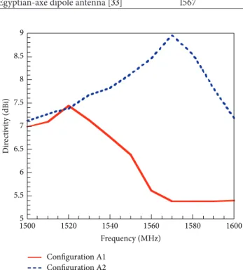
5 5.5 6 6.5 7 7.5 8 8.5 9 1500 1520 1540 1560 1580 1600 Dir ec ti vi ty (dB i) Frequency (MHz) Configuration A1 Configuration A2
Figure 13: Measured directivity of the studied antenna with
cou-pling distance𝑑1: (a) configuration A1 (𝑑1= 4 mm), (b)
configura-tion A2 (𝑑1= 1 mm).
By analyzing results from Table 2, we remark that the
overall efficiency is usually higher at the lower resonance frequency (except for measured value of A1). We should mention, for example, that, for lower frequency of antenna A1, the high value of the overall efficiency (OE = 96%) drops clearly when we remove the SRR resonator, which confirms the main role of the metamaterial-cell in the amelioration of the directivity.
The measured radiation patterns of the antenna for both
configurations A1 and A2 are illustrated inFigure 12. We can
remark that the antenna focuses its radiation in the half-space situated above the ground plane. This behaviour is due to the coupling effect between the monopole and the SRR in addition to the presence of the ground plane. We should note that, by increasing the size of the ground plane, we may improve the directivity of the proposed antennas by minimizing the back radiation.
As shown inFigure 13, the maximum measured
directiv-ity of the antenna is around 7.5 dBi for configuration A1 and
9 dBi for A2. As predicted by simulation inFigure 5(a), the
configuration A2 seems to be more directive than A1. This may be explained by the ground plane coupling effect which is more important in configuration A1 than A2.
The improvement of the antenna directivity is due essen-tially to the coupling effect between the monopole and the SRR which affects the surface currents in the structure and
then the whole antenna radiation behaviour, especially its gain and directivity.
In order to better evaluate the performances of the optimized structure A1, we have compared it to two similar
antennas [32,33] in terms of size (𝑘𝑎), efficiency (OE), and
gain.Table 3regroups the obtained results.
The “Z-antenna” is a metamaterial-inspired structure that incorporates a lumped inductor element of value 19nH
to reduce its height [32], whereas the Egyptian-axe dipole
antenna [33] uses an electromagnetic band-gap (EBG)
struc-ture, which acts as an artificial magnetic conductor ground plane (AMC), in order to increase the gain.
By comparing the optimised antenna A1 to similar
struc-tures developed in [32, 33], we can situate it, in terms of
performances, between the Z-antenna and the Egyptian-axe dipole antenna. We have improved the gain (4.28 dB against 3.23 dB for the Z-antenna) and the size (𝑘𝑎 = 0.58 against 0.99 for the Egyptian-axe dipole antenna). Therefore, the directivity was slightly decreased but still high compared to conventional patch antennas.
4. Conclusion
The deep directivity analysis of a metamaterial-inspired compact monopole antenna was realized. It is shown that the proposed structure (SRR + monopole) with its two
config-urations A1 and A2 is compact (0.145𝜆0) and may exhibit
a superdirectivity behaviour. From the analysis of simulated currents distribution and shape of radiation patterns, we have proposed that the superdirectivity of the structure is due
especially to the monopole-SRR coupling (𝐷max= 7.5 dBi for
A1). This directivity may be improved further by optimizing
also the ground plane-SRR coupling (𝐷max= 9 dBi for A2).
Conflict of Interests
The authors declare that there is no conflict of interests regarding the publication of this paper.
Acknowledgment
This paper was funded by the Deanship of Scientific Research (DSR), King Abdulaziz University, Jeddah. The authors, therefore, acknowledge with thanks DSR technical and finan-cial support.
References
[1] K. L. Wong, Compact and Broadband Microstrip Antennas, John Wiley & Sons, 2004.
[2] R. C. Hansen, Electrically Small Superdirective and Supercon-ducting Antennas, John Wiley & Sons, New York, NY, USA, 2006.
[3] J. M. Laheurte, Compact Antennas for Wireless Communications and Terminals: Theory and Design, John Wiley & Sons, 2013. [4] R. W. Ziolkowski, P. Jin, and C.-C. Lin, “Metamaterial-inspired
engineering of antennas,” Proceedings of the IEEE, vol. 99, no. 10, pp. 1720–1731, 2011.
[5] A. Erentok and R. W. Ziolkowski, “A dual-band efficient
metamaterial-inspired electrically-small magnetic-based
antenna,” in Proceedings of the IEEE Antennas and Propagation Society International Symposium, pp. 1877–1880, Honolulu, Hawaii, USA, June 2007.
[6] P. Jin and R. W. Ziolkowski, “Broadband, efficient, electrically small metamaterial-inspired antennas facilitated by active near-field resonant parasitic elements,” IEEE Transactions on Anten-nas and Propagation, vol. 58, no. 2, pp. 318–327, 2010.
[7] S. Dakhli, K. Mahdjoubi, H. Rmili, J. M. Floch, and H. Zangar, “Compact, multifunctional, metamaterial-inspired monopole antenna,” in Proceedings of the 6th European Conference on Antennas and Propagation (EuCAP ’12), pp. 1967–1970, Prague, Czech Republic, March 2012.
[8] R. Goncalves, N. B. Carvalho, and P. Pinho, “Metamaterial inspired compact printed antenna for WLAN applications,” in Proceedings of the IEEE Antennas and Propagation Society International Symposium (APSURSI ’13), pp. 1382–1383, July 2013.
[9] S. Dakhli, J.-M. Floch, K. Mahdjoubi, H. Rmili, and H. Zan-gar, “Compact and multi-band metamaterial-inspired dipole antenna,” in Proceedings of the 7th European Conference on Antennas and Propagation (EuCAP ’13), pp. 2765–2768, Gothen-burg, Sweden, April 2013.
[10] P. Jin and R. W. Ziolkowski, “Low-Q, electrically small, efficient near-field resonant parasitic antennas,” IEEE Transactions on Antennas and Propagation, vol. 57, no. 9, pp. 2548–2563, 2009. [11] R. W. Ziolkowski, P. Jin, and C.-C. Jin, “Electrically small
metamaterial-inspired antennas: designs and measurements, efficiency and bandwidth performance,” in Proceedings of the IEEE International Workshop on Antenna Technology (iWAT ’09), pp. 1–4, March 2009.
[12] S. Dakhli, K. Mahdjoubi, J.-M. Floch, H. Rmili, and H. Zangar, “Efficient, metamaterial-inspired loop-monopole antenna with shaped radiation pattern,” in Proceedings of the Loughborough Antennas and Propagation Conference (LAPC '12), pp. 1–4, Loughborough, UK, November 2012.
[13] M. A. W. Nordin and M. T. Islam, “A bandwidth enhanced printed dipole antenna with metamaterial-inspired loading,” in Proceedings of the 3rd IEEE International Conference on Space Science and Communication (IconSpace ’13), pp. 182–185, Melaka, Malaysia, July 2013.
[14] M. S. Majedi and A. R. Attari, “A compact and broadband metamaterial-inspired antenna,” IEEE Antennas and Wireless Propagation Letters, vol. 12, pp. 345–348, 2013.
[15] N. Zhu, Q. Feng, and Q. Xiang, “Metamaterial-inspired high-gain array antenna,” in Proceedings of the Cross Strait Quad-Regional Radio Science and Wireless Technology Conference (CSQRWC ’11), pp. 375–378, July 2011.
[16] A. D. Yaghjian, “Increasing the supergain of electrically small antennas using metamaterials,” in Proceedings of the 3rd Euro-pean Conference on Antennas and Propagation (EuCAP ’09), pp. 858–860, Gothenburg, Sweden, March 2009.
[17] H. Mirzaei and G. V. Eleftheriades, “A compact frequency-reconfigurable metamaterial-inspired antenna,” IEEE Antennas and Wireless Propagation Letters, vol. 10, pp. 1154–1157, 2011. [18] O. Turkmen, G. Turhan-Sayan, and R. W. Ziolkowski,
“Metama-terial inspired, electrically small, GSM antenna with steerable radiation patterns and high radiation efficiency,” in Proceedings of the IEEE Antennas and Propagation Society International Symposium (APSURSI ’13), pp. 770–771, Orlando, Fla, USA, July 2013.
[19] J. P. Turpin, J. A. Bossard, K. L. Morgan, D. H. Werner, and P. L. Werner, “Reconfigurable and tunable metamaterials: a review of the theory and applications,” International Journal of Antennas and Propagation, vol. 2014, Article ID 429837, 18 pages, 2014. [20] H. A. Wheeler, “Fundamentals limitations of small antennas,”
Proceding of the IRE, vol. 35, pp. 1479–1484, 1947.
[21] L. J. Chu, “Physical limitations of omni-directional antennas,” Journal of Applied Physics, vol. 19, no. 12, pp. 1163–1175, 1948. [22] M. Pigeon, L. Rudant, C. Delaveaud, and K.
Belmkad-dem, “Antennes miniatures superdirectives,” in 18`eme Journ´ees Nationales microndes (JNM ’18), Paris, France, May 2013. [23] O. Luukkonen, A. O. Karilainen, J. Vehmas, C. Simovski, and S.
A. Tretyakov, “ high impedance surface based antennas-lose the antenna,” in Proceedings of the European Conference on Anten-nas and Propagation (EUCAP ’10), pp. 151–155, Gothenburg, Sweden, April 2010.
[24] P. Jin and R. W. Ziolkowski, “Metamaterial-inspired, electrically small huygens sources,” IEEE Antennas and Wireless Propaga-tion Letters, vol. 9, pp. 501–505, 2010.
[25] S. R. Best, “Progress in the design and realization of an electri-cally small Huygens source,” in Proceeding of the International Workshop on Antenna Technology: Small Antennas, Innovative Structures and Materials (iWAT '10), pp. 1–4, Lisbon, Portugal, March 2010.
[26] H. G. Schantz, “Directive, electrically-small UWB antennas,” in Proceedings of the IEEE International Conference on Ultra-Wideband (ICUWB ’12), pp. 227–231, Syracuse, NY, USA, September 2012.
[27] B. Sentucq, A. Sharaiha, and S. Collardey, “Superdirective metamaterial-inspired electrically small antenna arrays,” in Proceedings of the European Conference on Antennas and Prop-agation (EuCAP '13), pp. 151–155, Gothenburg, Sweden, April 2013.
[28] T. Taylor, “A discussion of the maximum directivity of an antenna,” Proceding of the IRE, vol. 36, p. 1135, 1948.
[29] H. Riblet, “Note on the maximum directivity of an antenna,” Proceding of the IRE, vol. 36, no. 5, pp. 620–623, 1948.
[30] R. F. Harrington, “On the gain and beamwidth of directional antennas,” IRE Transactions on Antennas and Propagation, vol. 6, pp. 219–225, 1958.
[31] A. Erentok and R. W. Ziolkowski, “Metamaterial-inspired efficient electrically small antennas,” IEEE Transactions on Antennas and Propagation, vol. 56, no. 3, pp. 691–707, 2008. [32] P. Jin and R. W. Ziolkowski, “Multiband extensions of the
electrically small, near-field resonant parasitic Z antenna,” IET Microwaves, Antennas and Propagation, vol. 4, no. 8, pp. 1016– 1025, 2010.
[33] P. Jin and R. W. Ziolkowski, “High-directivity, electrically small, low-profile near-field resonant parasitic antennas,” IEEE Antennas and Wireless Propagation Letters, vol. 11, pp. 305–309, 2012.
Submit your manuscripts at
http://www.hindawi.com
VLSI Design
Hindawi Publishing Corporation
http://www.hindawi.com Volume 2014
Machinery
Hindawi Publishing Corporation
http://www.hindawi.com Volume 2014 Hindawi Publishing Corporation
http://www.hindawi.com
Journal of
Engineering
Volume 2014
Hindawi Publishing Corporation
http://www.hindawi.com Volume 2014
Shock and Vibration
Hindawi Publishing Corporation
http://www.hindawi.com Volume 2014 Mechanical
Engineering Advances in
Hindawi Publishing Corporation
http://www.hindawi.com Volume 2014
Civil Engineering
Advances inAcoustics and VibrationAdvances in Hindawi Publishing Corporation
http://www.hindawi.com Volume 2014
Hindawi Publishing Corporation
http://www.hindawi.com Volume 2014
Electrical and Computer Engineering
Journal of
Hindawi Publishing Corporation
http://www.hindawi.com Volume 2014 Distributed Sensor Networks International Journal of
The Scientific
World Journal
Hindawi Publishing Corporation
http://www.hindawi.com Volume 2014
Sensors
Journal of Hindawi Publishing Corporationhttp://www.hindawi.com Volume 2014
Modelling & Simulation in Engineering
Hindawi Publishing Corporation
http://www.hindawi.com Volume 2014
Hindawi Publishing Corporation
http://www.hindawi.com Volume 2014
Active and Passive Electronic Components
Hindawi Publishing Corporation
http://www.hindawi.com Volume 2014 Chemical Engineering International Journal of Control Science and Engineering Journal of
Hindawi Publishing Corporation
http://www.hindawi.com Volume 2014 Antennas and
Propagation International Journal of
Hindawi Publishing Corporation
http://www.hindawi.com Volume 2014
Hindawi Publishing Corporation
http://www.hindawi.com Volume 2014 Navigation and Observation International Journal of Advances in OptoElectronics
Hindawi Publishing Corporation
http://www.hindawi.com Volume 2014
Robotics
Journal ofHindawi Publishing Corporation