Science Arts & Métiers (SAM)
is an open access repository that collects the work of Arts et Métiers Institute of
Technology researchers and makes it freely available over the web where possible.
This is an author-deposited version published in: https://sam.ensam.eu Handle ID: .http://hdl.handle.net/10985/8359
To cite this version :
Olivier COMA, Christian MASCLE, Philippe VERON - Geometric and form feature recognition tools applied to a design for assembly methodology - Computer-Aided Design - Vol. 35, p.1193-1210 - 2003
Any correspondence concerning this service should be sent to the repository Administrator : [email protected]
Geometric and form feature recognition tools applied to a design
for assembly methodology
O. Coma
a, C. Mascle
a,*, P. Ve´ron
b aDepartment de Mecanique, E´ cole Polytechnique de Montre´al, Section Fabrication, C.P. 6079 Succ. Centre-Ville, Montre´al, Que., Canada H3C 3A7
bENSAM, 2 Cours des Arts et Me´tiers, 13617 Aix-en-Provence, France
Abstract
The paper presents geometric tools for an automated Design for Assembly (DFA) assessment system. For each component in an assembly a two step features search is performed: firstly (using the minimal bounding box) mass, dimensions and symmetries are identified allowing the part to be classified, according to DFA convention, as either rotational or prismatic; secondly form features are extracted allowing an effective method of mechanised orientation to be determined. Together these algorithms support the fuzzy decision support system, of an assembly-orientated CAD system known as FuzzyDFA.
Keywords: Design for assembly; Bounding box; Symmetry; Feature recognition; Orientation analysis; Fuzzy logic
1. Introduction
Design for Assembly (DFA) is an important manufactur-ing tool that can substantially reduce the costs attributable to assembly. Besides cost reduction, DFA generates additional benefits such as higher quality, increased reliability, and shorter manufacturing time. A major effort was made to develop DFA methodologies during the eighties. Since their emergence, two different approaches have been investi-gated. The first method focuses on the evaluation of each elementary part of a product whereas the second considers the product as a whole[1].
The main reference used in this paper is the well-known Boothroyd – Dewhurst methodology [2] (B – D’s DFA), which can be applied to either manual or automated assemblies. A number of reference tables are used to evaluate each part in terms of ease of handling, ease of insertion as well as its relevance to the assembly. The findings are then compared to proprietary data. This evaluation process makes use of geometric and technologi-cal data for each part. From the geometric standpoint, parts are studied individually, whereas on the technological side, relationships between them are taken into consideration.
This work when combined with the author’s DFA methodology (in which fuzzy logic is introduced [3,4]) allows feature-based part codes to be used as input for DFA evaluation [5]. The technique described in this paper was developed to minimize designer inputs by performing a computerized geometric information search and using artificial intelligence to automate the DFA evaluation process through fuzzy logic. Fig. 1 provides the structure of FuzzyDFA; a fuzzy decision support system software, and demonstrates how a product and its parts are evaluated through the inference process.
The DFA knowledge base is composed of 29 fuzzy models which represent the Boothroyd – Dewhurst method-ology in its entirety. The part evaluation process uses technological and geometric data, as shown in Fig. 2. Geometric outputs become inputs for the inference process, and hence for fuzzy models. Therefore, specifying geo-metric requirements for DFA and implementing associated algorithms reduce manual inputs to technological information.
In this paper geometric requirements for manual and automated assembly operations are identified and an approach is proposed to automatically extract the required information from component geometric models. Then, an approach is described to compute a bounding box and doi:10.1016/S0010-4485(03)00026-5
symmetry characteristics of each part according to the DFA methodology. These geometric properties are qualified as basic DFA requirements since they are always used by the evaluation process, whether or not the assembly operations are automated, and operate on the original parametric B-Rep model of parts.
The evaluation of automated assembly operations requires further geometric information. The shape of each component must be analyzed in order to find how to automatically orient that part by mechanical selections. This key step in the Boothroyd – Dewhurst methodology requires 2D and 3D feature recognition processes as well as an algorithm to define the best orientation solution, i.e. combination of form features, for a part in order to insert it in the partial product in the most efficient way. For this purpose, the notion of feature orientation capability is introduced in the next sections. A faceted B-Rep model of parts is used in this paper for the 2D-form features extraction. Application of this model reduces the algorith-mic complexity. Various algorithms are presented for the 3D-form features extraction. They use the original para-metric B-Rep model of parts.
1.1. Overview of geometric requirements for DFA
Basic DFA requirements are always used for manual assembly analyses. However, feature recognition processes
are only needed for automated assembly operations.Table 1
lists geometric requirements for the DFA methodology used.
Dimensions L; D for rotational parts and A; B; C for non-rotational ones, with the symmetry axes X; Y; and Z are computed from a part’s minimal bounding box (see Section 4).
bðaÞ symmetry is the angle through which a part must be rotated around its insertion axis (an axis perpendicular to its insertion axis) in order to repeat its orientation. The insertion axis is defined manually in the FuzzyDFA system. Boothroyd – Dewhurst [2] dedicates specific Tables for defining the orientation of parts in automated assembly operations. Parts are oriented and distributed by bowl feeders. These bowls perform mechanical selections that define, step-by-step, the orientation of a part. During each step, non-conforming parts are discarded as shown inFig. 3. For a non-rotational part, 2D features in one or more planar projections, i.e. projections along X; Y; Z axes of the bounding box respectively named ProjX, ProjY, ProjZ, could be used to partially or completely define the part orientation (Fig. 3). 2D steps and 2D groove features are of interest when a part is progressing in a straight-line movement. But 2D features alone might not be adequate to orient a part. For example, if the component shape is a cube with a blind hole on one of its faces, no 2D feature could be detected in a 2D projection. The only feature that can be used to orient the part is its blind hole, i.e. a 3D feature.
Fig. 1. Organization diagram of the FuzzyDFAapplication (KB: knowledge base).
Fig. 2. Data required for DFA evaluation.
Table 1
Part geometric characteristics required
For a rotational part the Boothroyd – Dewhurst’s Table refers toasymmetry andbsymmetric (2D and 3D) features to orient the part relative to its end faces. The former Table exploitsbsymmetry andbasymmetric features to orient the part around its Z axis. In the B – D’s DFA technique, operation time for automatic manipulation for a prismatic part or a cylindrical part is evaluated in terms of ease of handling using three Tables. For the part shown inFig. 11, B – D’s DFA code is 21400. From the first table (correspond-ing to the fourth table in B – D’s DFA), 2 is deduced as the first number in this code because the part is rotational and its shape is a long cylinder because L=D . 1:5 (L and D are, respectively, the length and the diameter of the component’s cylindrical bounding box). From the second table (corre-sponding to the fifth table in B – D’s DFA), 1 is deduced as the second number because the part isaasymmetric and contains absymmetric step feature. It could be supported by a large flange and the center of gravity is below the support face. Continuing from the second Table, 4 is deduced as the third number because the part isbasymmetric and contains ab
asymmetric chamfer. From the third table (corresponding to the seventh Table in B – D’s DFA), 00 are deduced as fourth and fifth code numbers because the part is a normal size, with a non-abrasive surface, is not flexible, non sticky, non tangling, etc.
Lastly, Boothroyd – Dewhurst methodology requires feature type, axis and size information. Type and axis allow deduction of feature orientation efficiency, while the size is used to place features that have the same orientation capacity in order by decreasing size. This technique allows the selection of the most appropriate feature among partner features (same type, same axis) to design the bowl feeder. Feature decomposition is useless for DFA since partitioning two intersecting features does not help solve the orientation problem. The aim of the orientation algorithm is to select the most appropriate features that maximize the orientation efficiency of a part. Therefore, partitioning features may only influence the number of features required to orient the part. The next section introduces previous works related to the topic of this paper.
2. Related works
Li and Hwang [6] developed a semi-automated system that closely follows Boothroyd – Dewhurst methodology. Their approach considers multiple assembly sequences and times all feasible ones. However, they perform limited feature recognition for assembly and many of the geometric and non-geometric required information must be input manually.
In Ong and Lye [7], Rosario [8], a wire-frame representation scheme of the CAD part model is used in the development and implementation of computerized algorithms to calculate overall dimensions and rotational symmetries. Although algorithms are based on topological
relationships and a palindrome search, the wire-frame geometric model restricts them to very simple parts due to the lack of topological information inherent to this geometric representation.
Sturges and Kilani [9] built an analysis system that enables the extraction of several features (dimensions, shape, and symmetry of a part) relevant to assembly processes. Although a feature recognition process is described, their work does not refer to a systematic technique for solving the orientation problem.
None of these works systematically meets all the DFA geometric requirements, and hence, they lack geometric reasoning capabilities. This shortcoming is addressed using the approach demonstrated in this paper. The traditional role of automatic feature recognition in CAD is to identify the machinable features on a 3D CAD model of a mechanical component. There are a large number of research papers on Feature Recognition Algorithms for machining and this review contains only a sample. For a more complete review of automatic feature recognition methods, the reader is referred to Han et al.[10]or Marefat and Ji[11].
A review of the literature reveals that features are defined in different ways by various authors. Each author uses his own definition which, in fact, translates his specific point of view on the product model according to its application. In developing the SCAP system however, the widest definition possible was adopted (Jabbour et al.[12]).
Definition 1. An assembly feature (AF) is defined as any topological, geometrical, technological or functional infor-mation assigned to a face, a part or a sub-assembly, whose presence is inherent to the assembly process.
In this work for FuzzyDFA, Boothroyd – Dewhurst’s DFA[2]definition was adopted. Boothroyd – Dewhurst[2]
introduced the concept of the degenerated envelope in order to find a DFA minimal bounding box for a part. Essentially, the degenerated envelope is the cylinder, or rectangular prism obtained when small geometric details of the part, visible on planar projections, are neglected. Although this approach provides good theoretical results, it uses the relative notion of feature size, implying that criteria to decompose features must be found. This bounding box search process has proven to be difficult to automate.
Finally, literature abounds on feature recognition. ‘Fea-ture technology’ [13]describes advances in feature recog-nition as well as the contexts in which features are of interest. A form feature can be defined as a partial form or a part characteristic that is considered as a unit and that has a semantic meaning in design, process planning, manufactur-ing, cost estimation or other engineering disciplines [13]. Feature recognition is a post-processing technique, meaning that some procedures need to be applied to the geometry of a part in order to recognize its features. Approaches can be classified into five main groups[14,15]as follows:
Edge-based recognition. This is the oldest method, which interrogates each edge in a B-Rep model to ascertain whether the edge is concave, convex or smooth (extension of filleted edges). Specific rules are then applied to faces that share concave edges in order to select candidate faces to form a valid feature[16],
Volume and convex decomposition. This technique uses the resulting volumes of the subtraction of the convex hull of the part by the part itself. Thereafter, an iterative process attempts to generate a destructive solid geometry (DSG) tree for each of these volumes, using the alternating sum of volumes technique[17,18],
Graph-based recognition. Graph-based algorithms organize B-Rep information of a component into graph structures. These graphs can have either faces, edges or vertices as nodes and any of the other two-entities as arcs. During process recognition, these graphs are split into sub-graphs using well-developed graph manipulation algorithms, until each sub-graph matches a predefined feature graph[19],
Neural network-based recognition. Artificial neural nets have been studied for many years in hopes of achieving human-like performance. Since inputs and weights of each node are allowed to change over time, the neural net can be said to adapt and learn. Through learning, it can collect characteristics of a geometric/topological pattern and recognize existing useful features. The main advan-tage of neural nets over graph-based approaches is that they can tolerate a slight input error during learning or solving problems [20]. Therefore, the net can make a reasonable guess when problems are outside the range of its learning experience, and this property can be exploited in recognizing componential or interrupted features. But the learning process needs a large number of component samples and hence limits current implementations of neural-net techniques,
Rule-based recognition. Features are defined by sets of rules. The recognition process consists in matching the geometric properties and the topological data structure of the component with established rules[21]. The general form of a rule is: If ðA1; …; AnÞ Then F, where ðA1; …; AnÞ
is the set of conditions that define the feature F: Topology of the component is often the root of rule-based approaches. This type of technique requires a large number of rules in order to explore a wide domain of features, and is inadequate for separating intersecting features, i.e. complex feature decomposition is difficult to perform. But the technique is simple to implement and meets DFA requirements in terms of features.
3. Part and product data structures
Before developing how DFA requirements are solved, data structures used in FuzzyDFA, especially feature classes, are described in this section. As shown inFig. 4, the part class
aggregates technological characteristics represented by fuzzy sets (i.e. the material), component assembly charac-teristics (i.e. mating with other parts), and geometric characteristics (i.e. symmetries, form features). Appending product assembly characteristics such as the rate per hour of an assembly operator, allows the part class to be extended to support a product. Form features are the most complex geometric characteristics used in FuzzyDFA. Two classes were created to handle 2D and 3D features. The minimum information contained in each of them is as follows: † The faceted B-Rep model of the feature’s underlying
geometry,
† The identified feature type, † The measured feature size, † The feature axis.
Fig. 4 highlights the two CAD representations used in FuzzyDFA. CAD systems are currently used to describe a part by a parametric based B-Rep solid model in order to enable efficient product data management. In FuzzyDFA, geometric and topological entities of such a model are described using the STEP AP203 standard. Downstream engineering applications however, such as finite element analysis, may use other representations of the part. A faceted B-Rep model generated by a tessellation process on the parametric based original model is used to solve the DFA requirement problem. The tessellation is based on a Delaunay method and built according to a user-specified precision.
4. Basic geometric requirements
Although basic geometric requirements seem easy to find, dimensions and symmetries depend on the 3D Fig. 4. Part and product data structures used in FuzzyDFA application.
coordinate system attached to the part. When using a 3D modeler, designers usually create parts in a global 3D coordinate system which is predefined for a given product or sub-product by the product architect. But there is no a priori reason to ensure that this coordinate system is convenient to measure basic DFA requirements. Consequently, a minimal bounding box for each part must be first computed to enable DFA evaluations.
4.1. Minimal bounding box for DFA
For a given part, the approach is based on a topological exploration of its parametric based B-Rep model. The proposed algorithm explores this model to classify the part as rotational or not. To this end, faces of the B-Rep model are grouped into different sets to identify the main shape characteristics of the part. The proposed approach is illustrated with the part inFig. 5:
The first step consists in classifying faces of the part model into three sets: FPLN gathers planar faces, FREV for
revolution faces and FOTH for other geometric faces
(free-form faces). The FPLNset is then sub-structured by grouping
faces with the same normal. In the same way, the FREVset is
sub-structured by grouping faces with the same revolution axis or the same centre point for spherical faces. Inside the FPLN set, some faces must be differentiated. For example,
although both end faces of a cylinder are planar, they contribute to make the part rotational. Consequently, for each planar face f; a test evaluates whether it must be added to the FREVface set or not. This test explores edges of each
planar face and gathers them in two sets: circular and other. Then, the total length L1of edges in other sets is compared
to the longest edge L2 in a sub-set of the circular set.
Sub-sets of the circular set are obtained as before by grouping circular edges which have the same centre point. If L1. L2
then f is added to FPLN; else to FREV: For the part shown in
Fig. 5, the results are:
FPLN¼ {{f1; f4; f9}; {f3; f5; f7}; {f2; f6}{f8}};
FREV¼ {{f11; f12}; {f13; f14}; {f10}}
and
FOTH ¼ { }:
The second step performs new grouping operations (GFPLN,GFREV) on the FPLNand FREV sets to highlight the
main shape characteristics of the part and to conclude on its classification as rotational or not. Face sub-sets of FPLNare
grouped if they have collinear or perpendicular normals. In the same way, a planar facefpl of the FREV set is grouped
with sub-set ðFREViÞ of FREVif the centre point of the longest
circular edge of fplis located on the revolution axis of FREVi:
For the part shown inFig. 5, the results are: GFPLN¼ {{f1; f2; f3; f4; f5; f6; f7; f9}; {f8}};
GFREV¼ {{f10; f11; f12; f13; f14}}
and
FOTH ¼ { }:
The areas (Area_GFPLN and Area_FOTH) of GFPLN and
FOTH sets are computed as the sum of all the face areas of
the set, and the area (Area_GFREV) of the GFREVset is also
computed as follows: Area_GFREV¼ sup
n
i¼1
ðarea_GFREViÞ ð1Þ
where: area_GF .REVi is the area of the sub-set i of the
GFREVset.
Finally, the part is classified as rotational if Area_ GFREV. ðArea_GFPLNþ Area_FOTHÞ: Rotational parts
described using free-form surface patches (Be´zier, B-Spline, NURBS) are not identified using this approach but such parts are not frequently encountered in the design of mechanical products. In accordance with this approach, the part described in Fig. 5 will be classified as non-rotational.
The last step of the approach assigns a 3D coordinate system to the part which is the support for its bounding box. From a mechanical engineering point of view and as per the DFA methodology requirements, a 3D coordinate system is defined from the three main inertia axes of the part and its origin is located at the inertia centre point. The bounding box of minimum volume that encloses the part is thus built from this 3D coordinate system using classical algorithms
[22]according to the following rules: for rotational parts, the Z axis is chosen along the rotational axis previously identified and, for non-rotational parts, the X axis is chosen corresponding to the largest dimension of the bounding box and the Z axis to the smallest one.
4.2. Symmetries
In DFA methodology, a and b symmetry properties defined in Section 1 are required to estimate the orientation and insertion part efficiency in the assembled product and to correctly orient the parts for automated assembly operations. Partial symmetry detection processes [23] can be useful for roughly orienting a part but are not convenient to automated insertion operations since the part must be well oriented. The method used here is based on existing works[24], and the complete rotationalaandb
symmetry properties are detected. A part is considered to beaorbsymmetric if an angleFexists (F¼ 3608=n with
n $ 2) around an appropriate axis D such that the intersection volume between the part before and after rotation of Faround D is null (or close to zero). For the DFA orientation approach described in Section 5,aandb
symmetry properties are sought for each part around the three axes of its associated coordinate system previously defined.
5. Feature recognition processes 5.1. 2D feature recognition
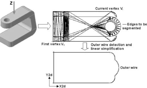
When a part is conveyed into a bowl feeder, 2D projections of its geometric model enable the definition of possible solutions for its orientation. Relevant features are those relative to the 2D bounding box of these projections. This section details the 2D-feature recognition process proposed to extract these relevant features for DFA purposes. First, the outer wire of the part projection is computed using standard classical routines (Fig. 6). To increase the algorithm efficiency and reduce computation time, the part faceted model is simplified using a vertex based removal technique previously developed [25]. The decimation is processed according to a user specified tolerance e and redundant vertices and edges of length inferior to eare removed.Fig. 6shows the part outer wire computation for a Z axis projection.
A planar face f is then created on the outer wire defined and subtracted from f_bnd2D; the rectangular face that
bounds the outer wire face. The set of faces N thus produced ðN ¼ f_bnd2D2 f Þ is the basis for the feature
detection process. Four kinds of 2D features are defined to fulfil DFA requirements: Feat2d_Groove, Feat2d_Step, Feat2d_Other and Feat2d_Nothing. For each face fNi
belonging to N; the type of the related feature is found according to the bounding box bnd2Dand the area of face f
according to five rules:
Rule 1. A face fNi that is made of less than three
different vertices is of type Feat2d_Nothing.
Rule 2. A face fNi that has two vertices on a border of
bnd2Dis of type Feat2d_Groove.
Rule 3. A face fNi that has three vertices on a border of
bnd2Dis of type Feat2d_Step.
Rule 4. A face fNi that has only 1, or more than three
vertices on a border of bnd2Dis of type Feat2d_Other.
Rule 5. A feature, of the type different to Feat2d_Noth-ing, and with an area inferior to 0.01 times the area of the face f; becomes type Feat2d_Other.
Fig. 7 shows step-by-step application of the described procedure and its associated rules; three features are identified. Features numbered 1 and 2 are recognized as steps (Feat2d_Step) whereas number 3 is of type ‘other’ (Feat2d_Other). It would have been of type groove (Feat2d_Groove) had its area been superior to 0.01 times the area of f: In the case of a more geometrically complex part, a classical shape healing algorithm[26]is applied to each face fNi in order to make a polyhedral approximation
on the original B-Rep model. Fig. 8 shows the effect of using an algorithm of this type.
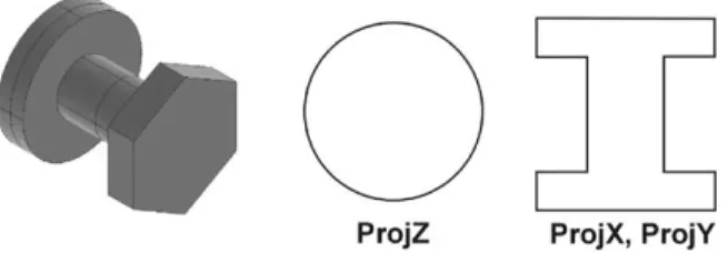
For a non-rotational part, this recognition step is performed for each of the three projections ProjX, ProjY and ProjZ. For a rotational part however, computing these three projections makes no sense. Indeed, the feature recognition process serves only as input for the orientation problem. Boothroyd – Dewhurst’s criteria are based on relationships between a and b symmetries and the features. For a symmetry, none of the three
projections provide reliable information (Fig. 9). But, the 2D features found on ProjX or ProjY are of interest for b symmetry.
In the general case however, ProjX and ProjY are different. The projection Projpis defined as:
Projp¼ ProjX[ [ n i¼0 ProjFeat3Di ! ð2Þ
where ProjFeat3Di; the projection of each 3D feature along X;
is used to find thebsymmetric features. Thus, the feature recognition process for a rotational part must first identify the 3D features. Fig. 10 shows how to find Projp for a sample part:
1. 3D features identification,
2. projection of each 3D feature along the projection axis, 3. union of all the projections.
Lastly, a feature selection test is performed in order to avoid counting the b symmetric features twice. This test consists in deleting each feature that has vertices of its
Fig. 7. 2D features detection.
Fig. 8. Effect of polyhedral shape healing process.
symmetric, along the insertion axis, which are included in another feature.Fig. 11shows this process.
5.2. 3D feature recognition
For the sake of simplicity, the proposed approach uses different recognition techniques depending whether the part
is rotational or not. Five types of features are identified: Feat3d_Step (steps, bosses, notches, chamfers and fillets), Feat3d_Groove, Feat3d_Cavity (holes and pockets), Feat3d_Other and Feat3d_Nothing. First, faces that are candidates to form a feature are gathered. Three algorithms were implemented in order to detect the maximum number of features:
1. An inner loop-based algorithm, 2. A vertex vexity-based algorithm, 3. A local topology analyzer.
Then, a rule-based identification process was applied to every feature in order to determine its type. All the 3D features of a part were gathered in the set F3d: From general methods [13], the authors developed original recognition methods or used known methods such as the inner loop-based algorithm. The inner loop-loop-based algorithm recog-nition process aims to find features of type Feat3d_Cavity. Faces in contact with an inner loop of a face are candidates to form such a feature (Fig. 12).
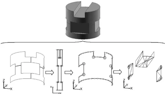
The vertex vexity-based technique, an original method, complements the original ‘edge vexity based’ method developed from the general method described by Parry-Barwick and Bowyer [13]. The vertex vexity-based technique allows the detection of steps, notches and grooves. The algorithm begins searching the outer wire W of each face f: Then, W and the underlying parametric surface S of f allow definition of W2d; the outer wire of f in the parametric coordinate system ðu; vÞ of S: At this point, concave vertices in W2d are gathered Fig. 10. Pre-processing for the 2D projection of a rotational part.
in the set V2d (Fig. 13). Then, for each vertex V2di in
V2d; both edges sharing Vj; i.e. Ej ðVj21; VjÞ and
Ejþ1ðVj; Vjþ1Þ; where Vj is the vertex in W that
corresponds to V2di; are selected.
Faces of the part sharing Ej or Ejþ1 are gathered to
form a partial feature. This procedure is reproduced while there are vertices left in V: Finally, features sharing a face are fused and the resulting features are appended to F3d: This algorithm uses the faceted B-Rep model of the part. This technique avoids studying, in the exact B-Rep model, inflexion points of the underlying geometric curve of each edge. However, this approach does not limit the feature recognition process. Indeed, at each inflexion point in the underlying geometric curve of an edge, lies a corresponding vertex of the same edge in the faceted model. Furthermore, if there is at least one concave vertex, whatever the model is, the face that contains this vertex is selected. There is no partition of faces along edges for which the second derivative vectors (along u and v axes), on the underlying geometric surface, are null. In general, the partition of a shape, whatever its topological type, involves topological modifications in the data structure of the part. This would lead to problems that are beyond the scope of this paper. It should be noted that such considerations have little interest in assembly since complex surfaces always get the poorest assemblability score. The latter have little sense in manufacturing also, since the more appropriate process for making a complex surface is a five-axis milling cycle, and decomposing this cycle into several similar cycles is usually redundant.
The inner loop-based algorithm is convenient to find cavities and bosses. The vertex vexity-based algorithm is more general and thus capable of detecting even more features, such as grooves and notches. However, neither
of these algorithms ensures the detection of chamfers and fillets in a part. Consequently, an original local topology analyser has been implemented. This analyser uses less time than the approaches presented in other works for manufacturing or design applications [27]. For example, in manufacturing applications blend radii could provide information that aids in selection of tools during machining and in the design application of blend recognition. Suppression is used for clean up operations in Finite Element Analysis. Often, in an assembly application, an analyser for detecting fillets and chamfers is less complicated. This local analyzer computes material angles for each face candidate to form a chamfer or a fillet. These faces are deduced from the GFPLN and FREV sets created when the minimal bounding
box was searched. In each sub-set of GFPLN and FREV; a
face not linked to another face is a candidate to form a chamfer. Sub-sets containing two conical (toroidal) faces in FREV undergo a specific process as they may form a
chamfer (fillet). Lastly, each valid chamfer or fillet is added to the 3D feature set F3d:
For each feature in F3d the following type identification algorithm is applied:
1. Type of each face in F3di is selected among planar,
rotational (cylindrical, spherical, conical, toroidal or of revolution) and other (B-Spline, of extrusion or offset), 2. Numbers of faces for each of the above defined types are
computed and are respectively named nb_pln, nb_rev and nb_oth,
3. In each face in F3di; numbers of free edges and
constrained edges (in contact with another face in F3di) are computed,
4. Number of faces, for which all edges are constrained, is computed,
5. Five rules are then applied in order to identify the type of F3di:
Rule 1. If there is only one face:
* If the face type is planar, then the feature type is
Feat3d_Step.
* If the face is cylindrical or other, the feature type is
Feat3d_Step or Feat3d_Groove depending on the location of the material.
Rule 2. If there is one face of which all edges are constrained then the type is Feat3d_Step (boss) or Feat3d_Cavity (blind hole or pocket) depending on the location of the material.
Rule 3. If each face has two constrained edges then the type is Feat3d_Cavity (hole or pocket through all).
Rule 4. If the proportion of constrained edges (number of constrained edges/total number of edges) in each face is $ 0.5 then the type is Feat3d_Step (notch).
Rule 5. If the proportion of free edges (number of free edges / total number of edges) in each face is $ 0.5 then the type is Feat3d_Groove.
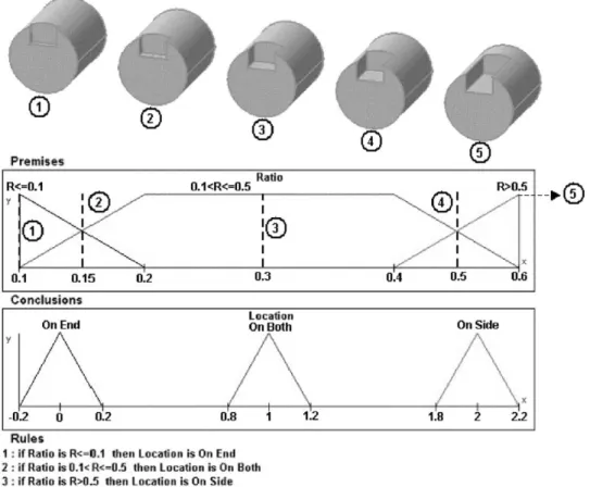
Illustrations of each rule are provided inFig. 14. For rotational parts, feature location is relevant to compute the orientation efficiency and a decision must be taken concerning whether a feature is located only on side faces of the part, or on both end and side faces or only on end faces. In order to remove any ambiguity, a fuzzy model representing the feature location was created as a function of the ratio L=D; where L is the depth of the feature and D the diameter of the cylindrical bounding box of the part. Dealing with uncertain knowledge calls for the use of the fuzzy decision support system implemented in FuzzyDFA.
Fig. 15shows the fuzzy representation adopted for feature location as well as part samples. The x-axis represents the R ratio L=D; and the y-axis the level of membership values between 0 and 100%. Using part number 2 as an example, the feature location is 50% ‘only on end faces’ and 50% ‘on both end and side faces’.
According to the rules defined in Fig. 15, Table 2
provides the fuzzy location of the groove for each part sample. During the DFA evaluation process, Fig. 14. Part samples for identification rules.
the orientation efficiency is computed by weighting, for each feature, results obtained for the three locations by the fuzzy location.
5.3. Measuring 3D feature size
Retrieving the volume of a feature in F3d is not an easy task. The features recognized above are made of faces that do not represent a closed shell. Therefore a reconstruction algorithm must be applied in order to create a convex closed shell that is significant in terms of manufacturing. This problem is complex however, and implies the addition of topological entities (like vertices, edges and faces) in the data structure of the part. Moreover, there is a need for rules to construct such entities. For example,Fig. 16shows three different solutions for filling a groove. Falcidieno and Giannini[28]introduce the notion of dummy entities similar to the notion of virtual entities defined by Brun[29]. In this paper the technique described by Brun[29]is used to build a convex closed shell for a feature from local topology.
Feature size is a measure that is only used to order 3D features by importance for DFA. Furthermore, in the feature selection process that defines part orientation, this measure is only relevant when several features have the same capabilities for orienting the part. In this case, the feature of maximum measured value must be selected. In order to overtake the volume retrieval issue the selected measure is the area of the plane-projected feature along its axis. The axis of a feature depends on the feature type. For example, the axis direction of a groove is the normal vector of the bottom face.
6. Part orientation
This section discusses the definition of an optimal part orientation as it relates to DFA methodology. Boot-hroyd – Dewhurst uses OE, the orientation efficiency, and FC, the relative cost of the bowl feeder, to characterize part orientation. The following approach selects features maximizing the objective function Fobj ¼ OE=FC;
analyz-ing 2D and 3D features orientation capabilities. The orientation is optimal in terms of OE and FC values.
6.1. Feature orientation capabilities
In order to define the part orientation, the proposed algorithm evaluates the inner symmetries and searches for symmetric features for each 2D feature in a 2D projection and for each 3D feature in the part. Six symmetry attributes ðsymX; symY; symZ; has_symX; has_symY; has_symZÞ are therefore added to the 2D and 3D feature data structures, as well as the feature usefulness.
2D feature orientation capabilities. Fig. 17 shows the meaning of these symmetries for 2D features.
For the 2D projection on the left inFig. 17:
† 1 has X inner symmetry (symX), † 2 has Y inner symmetry (symY).
For the 2D projection on the right inFig. 17, attributes has_symX, has_symY and has_symZ are true for features 1, 2, 3 and 4.
Symmetry symZ is not of interest for 2D features. According to the given definitions, no 2D feature can be symZ symmetry. Only features of type ‘hole’ or ‘cavity’ could have been symZ symmetry but they are not used in this approach due to their insignificance in the DFA method-ology. Furthermore, only ‘hole’ or ‘cavity’ features could have been both symX and symY inner symmetries.
Table 3 gives an indication of F2dik capabilities, the kth
feature of the projection i; where i [ {X; Y; Z}; depending on the number of its inner symmetries and the number of its symmetric features.
InTable 3, a case 2 feature, having one inner symmetry and one symmetric feature, is a feature that has one Table 2
Fuzzy location for part samples inFig. 15
Part number Ratio R Location
1 0.10 100% ‘only on
end faces’
2 0.15 50% ‘only on end faces’
and 50% ‘on both end and side faces’
3 0.30 100% ‘on both end and
side faces’
4 0.45 50% ‘on both end and side
faces’ and 50% ‘only on side faces’
5 0.80 100% ‘only on side faces’
Fig. 17. Symmetries used to define the projection orientation. Fig. 16. Topological entities to be added to fill a groove.
symmetric feature around Z (i.e. G2di), and hence, this
feature is case 2.Fig. 18shows part samples for each case. When a feature is quoted as useless (case 4 inTable 3), a specific case is taken into consideration: if the 2D bounding box of the 2D projection is squared and if this feature is a groove, then it is useful and is case 2 inTable 3, as it has a G2d-symmetric feature (i.e. its attribute has_symZ is true). Lastly, if F2dik is case 2 inTable 3, a 3D characteristic
axis, named Axis3D, is defined as the axis around which the
part can be 1808-rotated so the face representing the projection i stays the same before and after this rotation.
Table 4 provides the F2dikAxis3Dvalue, which is one of the
3D coordinate systems of the minimal bounding box, corresponding to a symmetry axis (inner symmetry and/or symmetric feature) of F2dik:
3D feature orientation capabilities. Table 5 presents F3di capabilities, depending on the number of its
inner symmetries and the number of its symmetric features.
Fig. 19shows part samples for each case.
6.2. Orientation for a non-rotational part
Ideally, a part would not require any feature to define its orientation so the distribution would have no mechanical selection. However, use of features is usually required. The system therefore attempts to bring the number of features
Fig. 19. Part samples for cases 1, 2, 3 and 4 inTable 5from the left to the right.
Table 5
Orientation capabilities for a 3D feature No. Number of
own symmetries
Number of symmetric features
Properties
1 0 0 Orients the part
2 0 1 This feature removes two
rotation axes for the part
1 0
3 0 2 This feature and one of
these symmetric features orient the part
4 0 3 This feature is useless
except for cubic part
1 1
2,3 0
5 1 2,3 Impossible
2,3 1,2,3
Table 4
Connection between 2D and 3D coordinate systems
Projection name 2D symmetry axis 3D axis
ProjX X2d Y0 Y2d Z0 G2d X0 ProjY X2d X0 Y2d Z0 G2d Y0 ProjZ X2d X0 Y2d Y0 G2d Z0
Fig. 18. Part samples for cases 1, 2, 3 and 4 inTable 3from the left to the right.
Table 3
Orientation capabilities for a 2D feature No. Number of own symmetries Number of symmetric features Properties
1 0 0 Orients the part
2 0 1 This feature removes two
rotation axes for the part
1 0
1 1
3 0,1 2 This feature and one of these symmetric features orient the part
4 0,1 3 This feature is useless 5 2 0,1,2, or 3 Impossible
down to a minimum. Steps and grooves are detected in 2D projections. The type of each 3D feature is assigned Feat3d_Cavity, assuming that whenever a feature is not visible in any 2D projection, whatever its actual type is, the part is as complex to orient as if it had a blind hole.
According to features capabilities, it can be established that 0, 1 or 2 features can define the orientation for a non-rotational part. The part orientation is completely defined whenever the part is superimposed on itself before and after a 1808-rotation around the X; Y or Z axis of its minimal bounding box. The following rules, summarizing all possible cases, help understand this purpose.
Rule 1. A useful 2D or 3D feature that has neither inner symmetry nor a symmetric feature can orient the part (Tables 3 or 5, case 1). The part orientation can thus be defined by only one feature.
Rule 2. If there is one axis U left, where U is one of the three minimal bounding box axes around which the part can still be rotated, we search for either a 2D feature, without U as Axis3D, or a 3D feature, without U as an inner symmetry
axis and without a U-symmetric feature to complete the definition of the part orientation.
Rule 2 uses features that correspond to case 2 inTables 3 and 5. This rule means that two features can define the part orientation: two 2D features, or one 2D feature and one 3D feature, or two 3D features.
Rule 3. If a feature removes one or two rotation axes, i.e. there are axes left around which the part can still be rotated, and if none of the other features can remove these axes, then the part can be oriented by this sole feature.
Rule 4. If no feature is able to remove any axis, then the part is naturally oriented by its bounding box shape.
In the following section, features are ordered to select the most easy-to-use features for designing mechanical selec-tions. The orientation process goes on until an orientation solution is found. First, an attempt to orient the part without using features of type other is performed. If this attempt fails, features of type other can participate in defining the part orientation. Each of these two attempts searches for an orientation solution using either one 2D projection, or two 2D projections, or one 3D feature, or one 2D feature and one 3D feature, or two 3D features. These criteria use rules 1 and 2, and are ordered by increasing technological difficulty. A failure of this second attempt means that the part might be oriented by only one 2D or 3D feature (rule 3). Lastly, if the former fails, the part requires no feature to define its orientation (rule 4).
Whenever two features are used to orient the part, the type and axis of the main DFA feature for defining the part orientation are those of the feature of minimum Fobj value.
Once the part orientation is defined, corresponding row and column indices, deduced from the fifth to seventh Tables of the B – D’s DFA technique, are computed to allow DFA evaluations to be performed.
Part orientation with one 2D projection. In each projection i; 2D features are ordered by decreasing Fobj value and decreasing size. Projection samples for the following cases are given inFig. 20:
(a) Search for a useful 2D feature compliant to rule 1 (case 1 inTable 3),
(b) If no such 2D feature is found, search for a couple of useful 2D features ðF2dik; F2dilÞ that can orient the
part: (b)-1
F2dik and F2dil do not have the same Axis3D value
(rule 2), (b)-2
Or, F2dikand F2dilare case 3 inTable 3.
Part orientation with two 2D projections. From this point, each projection has only 2D features that are case 2 or 4 inTable 3. For each couple ðProjX; ProjYÞ; ðProjY; ProjZÞ and ðProjZ; ProjXÞ; we search for a couple of two useful 2D features ðF2dik; F2djlÞ; i – j; i.e. one feature on each
projection, for which F2dikAxis3D–F2djlAxis3D; that
maximizes the orientation efficiency (rule 2). For example, the part in Fig. 21is oriented by both grooves (located in two different projections), which have different Axis3D
values.
Part orientation with one 3D feature. 3D features are ordered by decreasing value of their projected area. Then, Fig. 20. Projection samples for cases a, b-1, b-2 from the left to the right.
we search for a useful 3D feature compliant to rule 1 (case 1 inTable 5).
Part orientation with one 2D feature and one 3D feature. The technique consists of analyzing orientation capabilities of each couple ðF2dik; F3djÞ following rule 2.
Part orientation with two 3D features. From this point, each 3D feature is case 2 or 4 in Table 5. The technique consists of analyzing orientation capabilities of each couple ðF3di; F3djÞ following rule 2.
Part orientation with one 2D feature or one 3D feature. This attempt to orient the part consists of analyzing if one feature (2D or 3D), previously considered to partially orient the part, can then orient the part, since the part has no feature capable of completing the partial orientation of this feature. The implemented technique verifies the orientation capabilities of 2D projections and 3D features (Fig. 22).
(a) For each 2D projection Proji
(a)-1
Its bounding box is rectangular: if Proji is symmetric
around G2di; then no 2D feature in Projican define the
part orientation, else the useful 2D feature of maximum Fobjvalue is selected,
(a)-2
Its bounding box is squared: if Proji is superimposed
onto Projirotated around (Gi; 908), then no 2D feature in
Projican define the part orientation, else the useful 2D
feature of maximal Fobjvalue is selected,
(b) For each 3D feature F3di:
(b)-1
The part is not cubic: if F3diis useful then it can orient
the part. (b)-2
The part is cubic: F3dican orient the part.
6.3. Orientation for a rotational part
The following describes the implemented geometric interpretations of Boothroyd – Dewhurst Table criteria to orient a rotational part.
Retrieving indices of valid rows and valid columns are two independent steps. Therefore, the technique consists in optimizing the objective function Fobj while studying every couple (row, column) that is a suitable orientation solution. The overall algorithm is described below:
† Search for index of valid rows that define the set R; † Search for index of valid columns that define the set C; † Computation of Fobj for every couple ðRi; CjÞ;
† NR and NC are indices of the couple for which Fobj is
maximum.
Retrieving valid rows. The index of each row for which the part is compliant is added to the set R: Criteria for the eight rows are:
Row 0: ‘The part isasymmetric’.
Studying other rows becomes useless since Fobj is always optimal in row 0.
Row 1: ‘The part can be fed in a slot supported by large end (step feature) or protruding flange (chambered step feature) with its centre of mass below the supporting faces’. The 2D projection is used to verify compliance to this rule:
† Part centre of mass is projected onto this projection ðG2DÞ;
† Features of type Feat2d_Step for which at least one vertex is on the bottom edge E of the projection bounding box are gathered in the set Feat2d,
† For each feature in Feat2di, we search for VF; the farthest
vertex from E that belongs to the feature. If VFis located
above G2Dalong the Z axis then this feature validates the
rule (Fig. 23).
Row 2: ‘bsymmetric steps or chambers’.
If there is at least one b symmetric feature of type Feat2d_Step then the part conforms to this rule.
Row 3: ‘bsymmetric grooves, holes or pockets on both end and side faces’.
If there is at least one b symmetric feature of type Feat2d_Step, Feat3d_Groove or Feat3d_Cavity located on both end faces and side faces then the part conforms to this rule.
Row 4 (5 – 6): ‘b symmetric grooves, holes or pockets only on side (end) faces’.
If there is at least one b symmetric feature of type Feat2d_Step, Feat3d_Groove or Feat3d_Cavity located on side (end) faces, then the part conforms to this rule. Criterion in row 6 is difficult to compute but, as it is close to row 5 criterion, row 6 is ignored in the developed approach.
Row 7: ‘basymmetric features’. Fig. 22. Projection and part samples for cases a-1, a-2, b-1, b-2 from the left
This row means that the part has some features but none of them is able to orient the part relative to its end faces.
Row 8: ‘Small size features’.
All the features in the part are too small to be used by an automated assembly system. This row is added to R only if R is empty.
For the part inFig. 23, R ¼ {1; 2; 3; 4; 5; 7}: Indices 1 and 2 are from the b symmetric step. The b symmetric hole allows the addition of index 4, the b symmetric groove indices 3 and 5 (due to its fuzzy location), and the b
asymmetric step index 7.
Retrieving valid columns. The index of each column for which the part is compliant is added to the set C: Criteria for the eight columns are:
Column 0: ‘The part isbsymmetric’.
Studying other columns is useless since Fobj is always optimal in column 0.
Column 2 (3): ‘basymmetric bosses, steps or chambers located only on side (end) faces’.
The part conforms to this rule if there is at least one b
asymmetric feature of type Feat2d_Step or Feat3d_Step located only on side (end) faces.
Column 4: ‘Same criterion as in column 2 and 3 but features are located on both side and end faces’.
Column 5: ‘b asymmetric grooves visible on a view along Z axis’.
The part conforms to this rule if among the 3D grooves, the axis of one of them is collinear to Z:
Column 6(7): ‘b asymmetric grooves, visible on a side view, located on end (side) faces’.
The part conforms to this rule if there is at least one b
asymmetric feature of type Feat2d_Groove or Feat3d_-Groove located only on end (side) faces.
Column 8: ‘Small size features’.
All the features in the part are too small to be used by an automatic assembly system. This column is added to C only if C is empty.
For the part inFig. 23, there is only oneb asymmetric feature: it is the chamfer (Feat3d_Step) located on end
Fig. 24. Assembly sample: a diaphragm. Fig. 23. Part sample that conforms row 1.
faces, and hence C ¼ {3; 4}: Then, evaluation for couple (1,3), (2,3), (4,3), (7,3), (1,4), (2,4), (4,4), (7,4) are computed. Finally, a couple (1,3), that maximizes Fobj, is selected, i.e. the part can be oriented by theb symmetric step and thebasymmetric chamfer.
7. Case study
The assembly sample created in FuzzyDFA (Fig. 24) is a diaphragm to be assembled in automated operations.
When a designer computes an assembly evaluation each part is first assessed individually. Only geometric results are presented here. In the diaphragm, the bearing housing has the most complex geometry.Table 6 summarizes features found in the bearing housing geometry.
ProjX has two symmetric step features. Axis3Dof each of
them is Y:
ProjY has no features.
ProjZ has one groove feature, for which Axis3Dis Y; and
two features of type other (two small size steps), for which Axis3Dis Y:
There are four 3D holes and four 3D fillets, each of them having an Y symmetric feature. Lastly, the 3D groove has one inner Y symmetry.
In this part, neither one feature nor a feature combination can block the Y axis. However, the part can be oriented by one ProjX 2D step, i.e. the feature that has the best Fobj value.
For the sake of simplicity, only a brief description of the orientation solution for other parts follows:
Diaphragm plate. It can be oriented by one 3D hole feature,
Screw. It can be supported by its large flange (row 1) and it isb-symmetric (column 0),
Washer. It isaandb-symmetric, Nut. It is a and b-symmetric.
Considering that technological and assembly character-istics of each part have already been input in FuzzyDFA, the assembly evaluation can then be computed for the diaphragm. In this case the assembly efficiency is only 28%. The user must therefore reconsider the part’s design to improve the assemblability of this product.
8. Conclusion
FuzzyDFA was built in Visual Cþ þ and Open CASCADEe3.1 [30], which is a powerful 3D modeling kernel that consists of reusable Cþ þ object libraries available as Open Source. FuzzyDFA enables the creation of 3D assemblies as well as the DFA definition of each part, assuming that its geometry has already been modeled as per the STEP AP203 standard. DFA evaluation can be computed either on a time/cost basis or on a merit scale, for manual and automated operations.
This paper has defined most of the geometric information required for DFA. Weight, dimensions and symmetries are sufficient characteristics for computations in manual operations. For automated assemblies, the proposed approach focuses on the usage of bowl feeders, which were investigated in depth by Boothroyd – Dewhurst. These devices operate on the 2D projected form features of a part. A feature recognition tool is detailed in this paper as well as an original approach for defining the orientation of a part. The usage of two geometric models (exact B-Rep and faceted B-Rep) allows algorithmic effectiveness, using the advantages of both models while avoiding their drawbacks. Every geometric characteristic serves as an input for the fuzzy decision support system used in FuzzyDFA. In this way, FuzzyDFA intelligently automates the assembly Table 6
evaluation process by minimizing designer inputs. This use of fuzzy logic allows evaluation of each part in a product to be performed early in the design process even if the part design is not detailed enough or remains uncertain.
9. Future work
The corrective knowledge base is being implemented and will provide a rationale and suggestions for improving the design of every part. A major enhance-ment to FuzzyDFA would be the addition of an assembly/disassembly sequencing system that analyzes contacts and mobility of parts. Insertion axes of parts would be automatically found[31]and this would further reduce the number of user inputs required. Appending assembly features to the component data structure [12]
would even more improve the evaluation process, taking into consideration, at each stage of the assembly process, functional data in addition to geometric, technological and assembly data.
Further enhancements could focus on the development of additional concurrent engineering tools that use DFX methodologies, where X stands for any product life cycle phase. Technically, this would imply the use of multiple-view models [32], which would deal, for each part, with a master model and different engineering views articu-lated around it. This hypothetical approach would also be able to deal with enhanced multi-views features [33]— such as a form feature or a feature with a functional meaning at a higher abstraction level and appropriate recognition algorithms. Finally, a dedicated information system would manage all the product model data at a higher level [34]. All these enhancements would trans-form FuzzyDFA into a more general computer-aided design tool.
References
[1] Tollenaere M. Conception de produits me´caniques. Hermes, ISBN 2-86601-694-7; 1998.
[2] Boothroyd G, Dewhurst P, Knight W. Product design for manufacture and assembly. New York: Marcel Dekker; 1994. ISBN 0824791762. [3] Coma O, Mascle C, Ve´ron P, Moisan S. Application de la logique floue a` une me´thode de conception pour l’assemblage. Fourth International Industrial Engineering Conference, Aix-Marseille; 2001. p. 109 – 18.
[4] Coma O, Mascle C, Ve´ron P. Feature shape recognition tools dedicated to a design for assembly methodology. Proceedings of the Fourth International Conference on Integrated Design and Manufac-turing in Mechanical Engineering, Clermont-Ferrand, France; May 14 – 16 2002.
[5] Ames AL. Production ready feature recognition based automatic group technology part coding. Proceedings of the First Symposium on Solid Modelling Foundations and CAD/CAM Applications; 1991. p. 161 – 9.
[6] Li R-K, Hwang C-L. A framework for automatic DFA system development. Comput Ind Engng 1992;22(4):403 – 13.
[7] Ong NS, Lye SW. Geometric analysis of component design for assembly. J Des Manufact 1992;2(3):135 – 41.
[8] Rosario M. Automatic geometric part features calculation for design for assembly analysis. PhD Dissertation. University of Rhode Island; 1988.
[9] Sturges R, Kilani M. Towards an integrated design for an assembly evaluation and reasoning system. Comput Aided Des 1992;24(2): 67 – 79.
[10] Han J, Pratt M, Regli W. Manufacturing feature recognition from solid models: a status report. IEEE Trans Robot Automat 2000;16(6): 782 – 96.
[11] Ji Q, Marefat M. Machine interpretation of CAD data for manufacturing applications. ACM Comput Surv 1985;24(3): 265 – 311.
[12] Jabbour T, Mascle C, Maranzana R. A database for the representation of assembly features in mechanical products. Int J Comput Geometry Appl 1998;8(5/6):483 – 507.
[13] Parry-Barwick S, Bowyer A. Feature technology. University of Bath, Technical Report; January 1993.
[14] Regli W. Geometric algorithms for recognition of features from solid models. PhD Dissertation. University of Maryland; 1995.
[15] Febransyah A. A feature-based approach to automating high-level process planning. PhD Dissertation. North Carolina State University; 2001.
[16] Kyprianou L. Shape classification in computer aided design. PhD Dissertation. University of Cambridge; 1980.
[17] Lu Y, Gadh T, Tautges TJ. Feature based hex meshing methodology: feature recognition and volume decomposition. Comput Aided Des 2001;33(3):221 – 32.
[18] Waco DL, Kim YS. Geometric reasoning for machining features using convex decomposition. Comput Aided Des 1994;26(6): 477 – 89.
[19] Seed GM, Clark DER, Corney JR, Tuttle R, Little G. Object-oriented graph-based geometric feature recognition. Comput J 1996;39(9): 808 – 11.
[20] Prabhakar S, Henderson MR. Automatic form-feature recognition using neural-network-based techniques on boundary representations of solid models. Comput Aided Des 1992;24(7): 381 – 93.
[21] Donaldson I, Corney J. Rule-based feature recognition for 2.5D machined components. Int J Comput Integr Manufact 1993;6:51– 64. [22] Martin RR, Stephenson PC. Containement algorithms for objects in rectangular boxes. In: Strasser W, Seidel H-P, editors. Theory and practice of geometric modeling. Berlin: Springer; 1988.
[23] Tate S, Jared G, Swift K. Detection of symmetry and primary axes in support of proactive design for assembly. Proceedings of the Fifth Symposium on Solid Modeling and Applications, Ann Arbor, USA; 1999. p. 151 – 8.
[24] Martin RR, Dutta D. Tools for asymmetry rectification in shape design. J Syst Engng 1996;6:98– 112.
[25] Ve´ron P, Le´on J-C. Shape preserving polyhedral simplification with bounded error. Comput Graph 1998;22(5):565 – 85.
[26] Middleditch A. The bug and beyond. CSG 94 set-theoretic solid modelling techniques and applications; 1994. p. 1 – 16.
[27] Sashikumar V, Milind S. Blend recognition algorithm and appli-cations. Proceedings of the Sixth ACM Symposium on Solid Modeling and Applications, New York: ACM Press; 2001. p. 99 – 108.
[28] Falcidieno B, Giannini F. Extraction and organization of form features into a structural boundary model. Eurographics’87, Amsterdam: North-Holland; 1987. p. 249 – 59.
[29] Brun J-M. From characteristic shape to form features: a recognition strategy. Chapter 10 of advanced CAD/CAM systems, London: Chapman & Hall; 1995. ISBN 0 412 61730 7.
[30] OpenCASCADE,http://www.opencascade.com
[31] Rejneri N. De´termination et simulation des ope´rations d’assem-blage lors de la conception de syste`mes me´caniques. PhD
Dissertation. Institut National Polytechnique de Grenoble, France; 2000.
[32] Ve´ron P, Le´on J-C. Contribution to a multi-views, multi-represen-tations design framework applied to a preliminary design phase. Proceedings of the Second International Conference on Integrated Design and Manufacturing in Mechanical Engineering, Compie`gne, France; 27 – 29 Mai 1998. p. 1187 – 95.
[33] Noort A, Hoek GFM, Bronsvoort WF. Integrating part and assembly modelling. Comput Aided Des 2002; 34(12):899 – 912.
[34] Young B, Canciglieri O, Costa CA, Dorado JM, Zhao J, Cheung WM. Information support in an integrated product development system. Proceedings of the Third International Conference on Integrated Design and Manufacturing in Mechanical Engineering, Montre´al; 2000.
O. Comais a NCSimul R and D engineer at Spring Technologies in France. He received his MScA degree in Mechanical Engineering from E´ cole Polytechnique de Montre´al in 2002 and his engineering degree from E´ cole des Mines d’Ale´s (France). His research interests include design for assembly, geometric mod-eling and NC simulation.
C. Mascleis a full professor at Department of Mechanical Engineering, E´ cole Polytechnique of Montre´al. He received his PhD in Micro-technic Engineering from E´ cole polytechnique fe´de´rale of Lausanne, his BSc degree in Mechanical Engineering from E´ cole Polytech-nique of Montre´al, and his engineering degree in Microtechnic from Engineering School of Le Locle (Switzerland). His research interests include assembly and task planning, product life-cycle modeling, design methodology, intel-ligent CAD, tolerance modeling, and engineer-ing applications of object oriented programmengineer-ing. He is a member of SME.
P. Ve´ronreceived his PhD in 1997. He is associate professor at the E´ cole Nationale Supe´rieure d’Arts et Me´tiers (ENSAM) in France and a member of the Information and System Science Laboratory (LSIS), a CNRS unit. His research activity is centered on the development of geometric modelling approaches in the context of a multi-view and integrated design environment. A particu-lar interest is also brought to multisite collaborative design product approaches.