Science Arts & Métiers (SAM)
is an open access repository that collects the work of Arts et Métiers Institute of Technology researchers and makes it freely available over the web where possible.
This is an author-deposited version published in: https://sam.ensam.eu Handle ID: .http://hdl.handle.net/10985/9998
To cite this version :
Nicolas BOYARD, Mickaël RIVETTE, Olivier CHRISTMANN, Simon RICHIR - A design
methodology for parts using additive manufacturing - In: International Conference on Advanced Research in Virtual and Rapid Prototyping (VRAP), Portugal, 2013-10-01 - High Value
Manufacturing: Advanced Research in Virtual and Rapid Prototyping: Proceedings of the 6th International Conference on Advanced Research in Virtual and Rapid Prototyping, Leiria, Portugal, 1-5 October, 2013 - 2013
Any correspondence concerning this service should be sent to the repository Administrator : [email protected]
1 INTRODUCTION
Additive manufacturing (AM) is a very promising manufacturing process in terms of possibilities of shapes and complexity of parts (Vayre & Villeneuve 2012), (Boyard et al. 2012). It is possible to perform multi-material parts (Muller et al. 2010), hollow parts (Vayre & Villeneuve 2012), large-scale parts (Lim et al. 2012) and ready-for-use parts (Cooper et al. 2012).
From an ecological point of view, AM also al-lows the recycling of certain materials. For example, Fused Deposition Modelling (FDM), which is a method to construct a part from hot wire deposition, allows reuse of certain plastics such as acrylonitrile butadiene styrene (ABS).
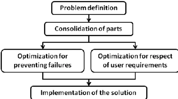
However, to design a product, it is necessary to adopt a precise and consistent methodology (Segonds 2011). Currently there are many methods whose relevance varies with the design goals: as-sembly, machining, cost, quality… (Tomiyama 2009). Among all these methods, there is a recurrent pattern (Figure 1).
Figure 1 : Standard schema of a design methodology (Se-gonds 2011)
However, although various redesign methodolo-gies have been proposed (Rodrigue 2010; Vayre & Villeneuve 2012), no design methodology has been developed specifically for AM.
Rodrigue (2010) reveal two design methodologies that may relate to the AM: The Design For Assem-bly (DFA), which aims to design a product in order to validate and facilitate assembly, and the Design For Manufacturing (DFM), whose goal is to design workable parts using one or more specific proc-ess(es) (Boothroyd 1994). In the case of AM, the geometry of the part is almost no longer constrained by the manufacturing process. To optimize the parts of the product with respect to the assembly and manufacturing, DFM and DFA can be performed di-rectly in the design without generating additional constraints or changes in the initial request of the end-user. Rodrigue (2010) also offers a redesign methodology (Figure 2).
Figure 2 : Redesign methodology for AM (Rodrigue 2011)
A design methodology for parts using additive manufacturing
N. Boyard, M. Rivette, O. Christmann & S. Richir
Arts et Métiers ParisTech, LAMPA, Angers, France
ABSTRACT: Additive Manufacturing (AM) allows designer to sidestep several design requirements and to create free forms, hollow parts or direct assemblies. This process also allows direct recycling of plastic into new parts, which eases the raw material supply. However, although several methodologies are used to redes-ign products and parts, none is dedicated to a real desredes-ign of parts and products in AM. At first, we will sug-gest the base of a new design methodology for an end-user who wants to create a product or a part in AM. Then, we will show an example of using our methodology. Finally, we will conclude on the limits of this methodology and on our next work to validate our methodology.
The resulting model is then optimized in two dif-ferent directions: preventing failures and respect for user requirements. Prevention of failures is based on FMECA (Failure Modes, Effects and Criticality Analysis). It aims to optimize the product to increase its reliability to meet the specifications. Compliance with user constraints aims to improve the design of each part to meet the design constraints with mini-mal compromise. The final purpose is to meet end-user’s needs as accurately as possible. Finally, the results of these optimizations are confronted to de-cide the structure and shape of the final product.
This paper aims to establish the basis of a design methodology that can take into account the specifici-ties of the AM. It doesn’t deal with innovation methodologies. In this paper, we deal only with the design of products which does not contain any inter-nal relative movement during use. These will be in-tegrated in future developments dedicated to opti-mize, test and then assess our method.
2 A MORE COMPLETE MEHODOLOGY 2.1 General overview
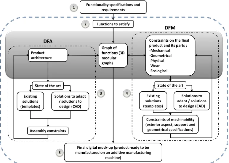
In the following sections, referring to our state of the art above, we present the fundamental keys to operationalize our methodology (Figure 3).
Our method includes the six steps of a standard design methodology: - Functional specification (1) ; - Conceptual design (2) ; - Architectural design (3) ; - Detailed design (4) ; - Implementation (5).
Phases 3 and 4, corresponding to loops of DFM and DFA, are performed in parallel.
The framework of our research regards points 3 to 5 of this methodology. We will assume that the work relating to the collection of needs and the planning tasks have already been made. In addition, we will not deal the implementation phase in its en-tirety. These two steps are necessary for any design methodology and do not participate in the design it-self. We also will assume that our methodology is consistent from the moment the designer is able to produce a manufacturable digital mock-up, corre-sponding to a prototype or to the finished product.
One of the difficulties in product design lies in the association of manufacturing and assembly with respect to the functional specifications. In our meth-odology, we propose to keep these two types of de-sign. But rather than to perform them separately and at different times, we try here to make them com-plementary and simultaneous.
In addition, the democratization of the AM (Anderson 2012) and the setting up of co-design phases in companies (phases with all stakeholders concerned with the whole product design: engineer-ing, stylists, end-user, designer ...) implies to de-velop a methodology that can be used by any person without any prerequisites.
2.2 Conceptual design
The conceptual design phase (Figure 3, step 2), which is the real starting point of our research, aims to take each function and constraint of the functional specifications.
However, changes from the client occur fre-quently throughout the product design. This is why the extraction of functions from the functional speci-fications should be flexible and modular to allow of new functions and constraints.
Once the features extracted, they will be arranged in a graph of functions by the actors of the design in order to provide a first iteration of the architecture of the final product. The first proposal is based on a simple set of rules that we need to define. Some of these rules concern, for example, the geometric ap-pearance. Thus a function requiring the holding in position of a part will be disposed downward, whereas a function requiring fast access to a part of the product is preferably placed on an outer sur-face... Similarly, the graph will be able to integrate new functions as and when the changes of the client.
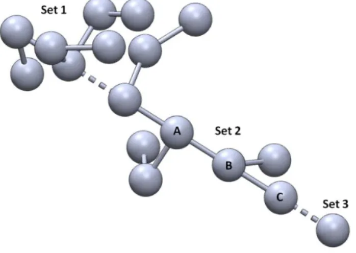
This graph is a modular three-dimensional graph to be drawn in CAD software and then to provide support to the digital mock-up (Figure 4).
Figure 4 : Graph of functions
The graph is a global representation of the prod-uct. As stated earlier, our methodology concerns only products containing no internal movement in functioning. However, these products can be com-posed of several parts. We therefore decompose the graph into several sets, each set representing a part of the product.
Since AM can manufacture any type of mechani-cal part, we assume that for any set of functions there is at least one piece that meets all the functions of this set. A part is defined here as a unitary physi-cal body.
The rules for establishing a set are:
- Is the part corresponding to this set a wear part?
- Can functions be grouped on the same part, or should they be separated?
- Are parts movable relative to each other? - ...
A set of functions is a collection of functions connected by links. A set must contain at least one function. If all functions of the functional specifica-tions are interconnected to others, then the graph will contain only one set. Sets are interconnected by dotted line representing a fixed joint between two parts.
Each function is represented as a sphere. The spheres are the nodes of the graph. The functions are then linked to each other by segments. These seg-ments represent both direct connections between functions and spatial organization of the functions with each other. Thus, different interconnected func-tions belong to the same part. In addition, a function A connected to a function B itself connected to a function C indicates that the function B will be found between or will separate functions A and C (Figure 4).
This representation allows the user of the meth-odology to spatially reorganize functions with each other. The advantage is, without conducting discus-sions of technical solutions, to begin to propose ar-chitecture of the final product based only on the functions and constraints to be addressed.
Moreover, this graph is modifiable: each function can be reorganized with respect to each other and connections can be changed. This has two advan-tages: the first is to provide a modular basis for dis-cussion with stakeholders of the design, the second is to allow stakeholders to easily review the results of the conceptual design.
2.3 Detailed design
The detailed design phase, which analyzes each set of functions present in the global graph of functions, corresponds to a DFM phase (Figure 3, Step 4).
Firstly, all the constraints that the part will sup-port are added to the set of this part. These con-straints can be mechanical, geometrical, physical, of wear, ecological...
Constraints are layered on geometry proposed by the global graph of functions.
In a first step, the CAD software will compare to a database the set corresponding to the part. This da-tabase contains all the graphs of functions already
designed by the design team and all the associated 3D models. It can be mutualised with other design teams. This corresponds to the state of the art step. Three alternatives are possible: either the proposed graph already exists and a piece is proposed. Other-wise, if a variant of the proposed graph (dependent on a minimum number of common functions) exists, it can serve as a basis for the design of the part. Ei-ther Ei-there is no corresponding or similar graph, the part has to be fully designed.
In the last two cases, the stakeholders will detail the geometry of the part and propose a combination of one or more materials to satisfy the constraints and functions imposed.
Finally, designers should specify an AM ma-chine. The geometry of the part will be confronted with manufacturing capabilities of the AM machine and assembly constraints with other parts.
If the part does not meet these criteria, the stake-holders will then optimize part by adjusting the fol-lowing parameters: part geometry, materials, func-tions of to the part.
If the part is valid, it is locked in the graph. If a function is added or removed to a part (which could be validated or not), it must again validate the de-tailed design phase.
2.4 Architectural design
The architectural design phase, or embodiment sign phase, is realized in parallel of the detailed de-sign phase (figure 3, step 3). Thanks to the modular-ity of the graph, the structure of the product may be modified whenever.
Each time a set is created or each time a part is validated during the detailed design, the architecture of the product must also be re-validated.
To proceed, as in the detailed design phase, the CAD software compare the entirely graph (and not a specific set) with the models of products of a data-base. This comparison could provide existing prod-ucts which give a model for the structure of the product and for the connections between the sets. This is particularly helpful to design a range of products or for mass customization (Zarb, F. 2012).
Otherwise, either an existing product may be fit, or, if there is no existing similar product, the archi-tecture is to be entirely designed.
Once the architecture of the product is designed, it is faced to the assembly constraints (removable or irremovable parts, accessibility to parts, steps of as-sembly/disassembly…). If the product fits the con-straints, it is validated. Else, the software indicates that the architecture has to be redesigned, which may lead to the transfer of one function from a set to an-other or to the internal reorganization of a set.
2.5 Co-design
Another purpose of this methodology is to allow the co-design of the product, involving all the stake-holders of design (end users, designers ...) at every moment of the design process.
Thus, if parts of the detailed design and the archi-tectural design are outsourced to CAD software for the searching of existing solutions, most of the de-sign is a result of subjective decisions of the stake-holders, especially those of end-users. This is why the co-design phase - including the conceptual, ar-chitectural and detailed design - should allow adding some constraints of appreciation:
- Physical (textures, distribution and percep-tion of product weight);
- Mechanical (flexibility, elasticity); - Geometric (grip, aesthetic);
- Architecture (type of mobile connection, dis-assembly);
- … 2.6 Deliverable
The purpose of our design methodology is to allow the user to manufacture his “own” product.
Once the product has been approved by all the stakeholders and the software no longer requires modification, parts resulting of the design will be post-processed by the CAD software to convert digi-tal files parts in a machine readable code.
This post-treatment has been validated during the detailed design phase. Indeed, at this stage, each part was confronted with the characteristics of the ma-chine which will manufacture them. The notions of surface quality, material manufacturing cost, ma-chinability, manufacturing strategy and precision are thus validated.
Once the manufacturing strategy has been vali-dated by stakeholders, the code is generated and the part is ready to be manufactured.
3 CASE STUDY: THE SALTCELLAR
To illustrate our methodology, we propose a sim-ple case study: the saltcellar.
For this, we use a simplified functional specifica-tion including the following nine funcspecifica-tions:
- F1: Contain condiments; - F2: Can be filled;
- F3: Distribute the content;
- F4: Protect condiments in case of fall; - F5: Indicates type of contained condiments; - F6: Indicates quantity of contained
condi-ments;
- F7: Do not slide; - F8: Hold on a table;
The first task of the design stakeholders will be to establish a graph of the functions.
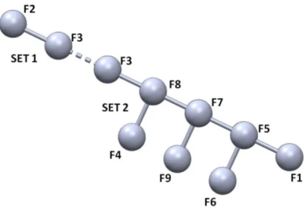
We will consider that the result of the discussion between the stakeholders, according to the rules of designed we will define, leads to a graph of two sets. The first one contains the functions F2 and F3. The second one contains the other functions (Figure 5).
Figure 5 : Graph of functions of the saltcellar
Then, the CAD software compares this graph to those which are contained in the database (functions and structure). An approaching solution is the salt-cellar with a metallic screwtop (Figure 6) which is a product also composed by two sets (Figure 7) which includes two other functions:
- F10: Limit the flow when distributing (set 1); - F11: Be washable (set 2).
Figure 6 : Saltcellar with metallic cap
Figure 7 : Graph of function of the saltcellar with screwtop
Function F3 « Distribute the content » is only contained in the first set. However, function F2 « Can be filled » is contained by both set 1 and set 2 and links them. Indeed, if the final product fits to the functional specifications, it is possible to duplicate a function, even it is redundant. In our case, this corre-sponds to the fact that the screwtop is screwed to the body of the saltcellar when used and unscrewed when filled: there is a relative movement only dur-ing the filldur-ing step. This matches with our methodol-ogy: when used; the screwtop is related to the body of the saltcellar by a rigid joint.
To fit exactly with the graph deduced from the functional specifications, the graph presented on the figure 6 may be modified and adapted.
Either functions F10 and F11 may be deleted re-spectively from set 1 and set 2, or the graph pre-sented on the figure 5 may include these functions (only if the end-user agree this modification of the functional specifications). Only the stakeholders of the design can make this choice.
Nevertheless, to fit the graph, it is necessary that every other function is satisfied. This involves the step of constraint of machinability from the DFM loop (Figure 3, step 4). According to the machine which will be used, stakeholders may have the pos-sibility to produce the body of the saltcellar in an en-tirely transparent material or to produce it in multi-material, at least one of them is transparent.
Once the graph is validated, stakeholders will be able to modify the position of the functions inside the sets to start to create the geometry of the parts.
In our case, since the software proposed an exist-ing solution, it is possible to base on the existexist-ing numerical model of this solution to design the ge-ometry of the parts. In every case, stakeholders will have to design the parts on the CAD software which allows the use of the graph of functions.
Here, the first set corresponds to the screwtop. The second corresponds to the body of the saltcellar.
By adding constraints on the sets, stakeholders will be able to design step by step the final geometry of the product and assign materials to the parts. In-deed, geometry and material must answer to the functional requirements. This will give the cost of raw material of the product.
In the case of imposed external parts, like an elec-tric motor-reducer, stakeholders have to know the exact geometry of these parts. They must have, at least, sharp diagrams to redesign and include these parts in the mock-up based on the graph in order to create the geometry of the product.
In our case, the body of the saltcellar may be made in transparent glass, to allow the end-user see the type and the remaining quantity of contained condiment. More, a glass saltcellar is easily wash-able. The type of glass and the geometry of the body
have to fit functions F4 « Protect condiments in case of fall », F7 « Do not slide », F8 « Hold on a table » and F9 « Being comfortable in hand ». These choices are delegated to the stakeholders. However, it is not possible to add a stick on the saltcellar to in-dicate the type of condiment. Otherwise, the graph would have been composed by three sets: one for the body, one for the screwtop and one for the stick.
As one goes along the design, the software veri-fies the respect of assembly and machinability con-straints, indicating the possible mistakes or incom-patibility. In this way, the mock-up resulting of the design is ready to be converted in a file which can be read by the additive manufacturing machines chosen to manufacture the product.
4 LIMITS
The methodology presented in this article is the sub-ject of a thesis, which can explain why some points have not yet been tested. Thus, the overall method-ology remains to be validated in an experiment in-volving different stakeholders (ergonomists, engi-neers, manufacturers, designers, end users...).
Moreover, it is difficult to estimate the cost of some developments which have to be done on the CAD software. If the technical feasibility of our methodology has been validated through the use of SolidWorks software (Kou X. 2005), which allows the addition of features such as the integration of a comparative database, the length and complexity of these developments has not yet been quantified.
Thus, the methodology proposed in this paper is still at an ideal level. However, it can make a precise statement of requirements and necessary develop-ments. These are all avenues of research to explore.
Another point to develop is how stakeholders will interact with to the function graph. There are differ-ent technologies for multiuser interaction (Kadri 2007). However, the challenge is to propose a suit-able solution for all stakeholders, for their vision of the design vision, their vocabulary or to their field of competence (Segonds 2011).
5 CONCLUSION
The methodology we propose will therefore allow to design parts made using AM, with the most accurate respect of the functional specifications.
More, it differs from other methodologies (Has-coet et al. 2011) by the use of the graph of function which transcribes the will of designing the geometry of the product the later as possible.
In addition, this methodology allows the design of parts with complex geometries by abstracting a large number of manufacturing constraints associ-ated with conventional methods (cutting angles,
ac-cess to cutting tool, lubrication, tool wear...). It also allows the design of parts satisfying both DFA and DFM in the earliest phase early of the design. This possibility will limit a priori costly late changes.
Finally, this methodology falls within the scope of environmental concerns by providing, for certain processes, the ability to produce parts by using only the amount of material necessary to the final volume (Boyard et al. 2012).
6 REFERENCES
Boothroyd, G. 1994. Product design for manufacture and as-sembly. Computer-Aided Design 26(7): 505-520.
Boyard, N. & Rivette, M. & Christmann, O. & Richir, S. 2012. Méthodologie de prise en compte de la Fabrication Addi-tive lors de la phase de conception. Proc. AIP PRIMECA. Le Mont Dore: France.
Cooper, D. & Stanford, M. & Kibble, K. & Gibbons, G. 2012, Additive manufacturing for product improvement at Red Bull Technology. Materials and design 41: 226-230. Hascoet, J.Y. & Ponche, R. & Kerbrat, O. & Mognol P. 2011.
From functional specifications to optimized CAD model: proposition of a new DFAM methodology. Proc. 5th
Con-ference on Advanced Research in Virtual and Rapid Proto-typing, Lieira: Portugal.
Kadri, A. 2007. Contribution de la réalité virtuelle à l'évalua-tion de produits, dans les phases amonts du processus de conception. PhD thesis. Université d’Angers: France. Kou, X. 2005, Computer-aided design of heterogeneous
ob-jects, PhD thesis, HKU, China.
Lim, S. & Buswell, R.A. & Le, T. & Austin, S.A. & Gibb, A.G.F., Thorpe T. 2012. Developments in construction-scale additive manufacturing processes, Automation in
con-struction 21: 262-268.
Muller, P. & Mognol, P. & Hascoet, J.-Y. 2010. Modeling and control of a direct laser powder deposition process for Functionally Graded Materials (FGM) parts manufacturing.
Journal of Materials Processing Technology 213(5):
685-692. Elsevier.
Rodrigue, H. 2010. Méthodologie de conception et d’optimisation de mécanismes fabriqués par fabrication ra-pide. Master thesis. Ecole Polytechnique de Montréal: Ca-nada.
Segonds, F. 2011. Contribution à l'intégration d'un environne-ment collaboratif en conception amont de produit. PhD the-sis. LCPI & LSIS, ENSAM. France.
Tomiyama, T. & Gu, P. & Jin, Y. & Lutters, D. & Kind, Ch. & Kimura, F. 2009. CIRP Annals - Manufacturing
Technolo-gy 58(2): 543-565. Elsevier.
Vayre, B. & Vignat, F. & Villeneuve, F. 2012. Designing for Additive Manufacturing. Proc. 45th CIRP Conference on
Manufacturing Systems. Athens : Greece.
Vayre, B. & Vignat, F. & Villeneuve, F. 2012. Metallic addi-tive manufacturing: state-of-the-art review and prospects.
Proc. AIP PRIMECA. Le Mont Dore: France.
Zarb, F. 2012. 3D printing: The new industrial revolution,