HAL Id: hal-01238833
https://hal.archives-ouvertes.fr/hal-01238833
Submitted on 7 Dec 2015
HAL is a multi-disciplinary open access
archive for the deposit and dissemination of
sci-entific research documents, whether they are
pub-lished or not. The documents may come from
teaching and research institutions in France or
abroad, or from public or private research centers.
L’archive ouverte pluridisciplinaire HAL, est
destinée au dépôt et à la diffusion de documents
scientifiques de niveau recherche, publiés ou non,
émanant des établissements d’enseignement et de
recherche français ou étrangers, des laboratoires
publics ou privés.
Implementation of a Fast Fourier Transform Algorithm
onto a Manycore Processor
Julien Hascoet, Jean-Francois Nezan, Andrew Ensor, Benoit Dupont de
Dinechin
To cite this version:
Julien Hascoet, Jean-Francois Nezan, Andrew Ensor, Benoit Dupont de Dinechin. Implementation of a
Fast Fourier Transform Algorithm onto a Manycore Processor. Conference on Design and Architectures
for Signal and Image Processing (DASIP), Sep 2015, Cracow, Poland. �10.1109/dasip.2015.7367270�.
�hal-01238833�
Implementation of a Fast Fourier Transform
Algorithm onto a Manycore Processor
Julien HASCOET, Jean-Francois NEZAN, Andrew ENSOR, Benoˆıt DUPONT de DINECHIN
Kalray, INSA, AUT, Kalray Universit´e Europ´eenne de Bretagne, France Auckland University of Technology, New Zealand
Email: [email protected], [email protected], [email protected], [email protected]
Abstract—The Fourier transform is the main processing step applied to data collected from the Square Kilometre Array (SKA) receivers. The requirement is to compute a Fourier transform of 219 real byte samples in real-time, while minimizing the power consumption. We address this challenge by optimizing a FFT implementation for execution on the Kalray MPPA manycore processor. Although this processor delivers high floating-point performances, we use fixed-point number representations in order to reduce the memory consumption and the I/O bandwidth. The result is an execution time of 1,07ms per FFT, including data transfers. This enables to use only two first-generation MPPA chips per flow of data coming from the receivers, for a total power consumption of 17.4W.
Keywords—Square Kilometer Array (SKA), Fast Fourier Trans-form (FFT), Parallel Programming, Many-Core Processor, Fixed-Point Arithmetic, Network-On-Chip
I. INTRODUCTION
This work takes place in the context of the SKA (Square Kilometre Array) project1, whose objective is to deploy
world’s largest radio-telescope for the next decades. Thousands of receivers will be deployed in three unique configurations in Africa and Australia. It will have an unprecedented scope in observations, exceeding the image resolution quality of the Hubble Space Telescope by a factor of 50, whilst also having the ability to image huge areas of the sky in parallel. The SKA project results will answer many questions regarding astrophysics, fundamental physics, cosmology and particle astrophysics, and will also extend the range of the observable universe. It will operate over a large range of frequencies from 50 MHz to 14 GHz as the dishes and dipole antennas will be equipped with high performance single pixel feeds.
This project not only requires very high performance in terms of computing but also long-haul links in order to transmit huge amounts of data. The SKA will have a total collecting area of approximately one square kilometer. The receivers will be located in deserts and the dimension of the power generation will be decided depending on the chosen computing equipment. Power savings are thus as important as the computing requirements.
The data bandwidth will exceed the current global Internet traffic. As the SKA project deals with a huge amount of data and low power computing, the SKA project constraints are related to both high performance computing and green
1http://www.ska.ac.za
computing. These requirements can only be met by using the last generation of embedded systems.
In radio astronomy, the increase of the computing capa-bilities is the main challenge to store and interpret collected data [1]. Embedded solutions for signal processing have relied for a long time on FPGA implementations, as their energy efficiency and compute performance are suitable for this type of processing. Nowadays, many-core architecture solutions designed to reach higher performances are available. Being software programmable, they will enable the development of innovative digital applications in the fields of image and signal processing, telecommunications, intensive computing, indus-trial automation, data management, storage and networking. The objective of this work is to demonstrate the effectiveness of many-core platforms in the SKA project, specifically the Kalray MPPA (Multi-Purpose Processing Array) processor which integrates 256 applications cores.
The current SKA [2] CSP (Central Signal Processor) Survey Correlator requires FFT processing of data sets with 219 real byte samples. The incoming data throughput of a
single receiver is 1 Giga bytes per second; therefore, the FFT processing needs to be done in 524µs. The first challenge is to implement a FFT algorithm that fully exploits the execution parallelism and the on-chip memories of the platform. The second challenge is to feed all the MPPA compute clusters with data to compute and return back the results to the host CPU in real-time. Our implementation computes at an optimal precision and also optimizes data transfers between cluster of cores by leveraging the Network-On-Chip capabilities. As a result, only two MPPA processors are needed per flow of data, for a power consumption of 8,7W per processor.
This paper is organized as follows. The Kalray MPPA-256 Andey processor is introduced in Section II. Background on FFT and previous work are presented in Section III. Section IV describes the proposed algorithm and its implementation on the MPPA architecture. The results of the application are presented in Section V. Finally, Section VI concludes and proposes directions for future work.
II. THEKALRAYMPPA ANDEYPROCESSOR
The Kalray MPPA (Multi-Purpose Processing Array) many-core architecture is designed to achieve high energy effi-ciency and deterministic response times for compute-intensive embedded applications. The first MPPA-256 many-core pro-cessor, code-named Andey, integrates 256 VLIW application
cores and 32 VLIW management cores operating at 400MHz on a single chip and delivers more than 500 Giga operations per second for a typical power consumption of 12W.
The 256 VLIW application cores of the MPPA-256 Andey processor are grouped in 16 compute clusters connected with each other by a dual Network-On-Chip (NoC). Each cluster has 2 MB of locally shared memory called SMEM, of which 1.7 MB are available for application code and data, as 0.3 MB are taken by system software. In addition to the 16 compute clusters, the MPPA-256 Andey processor includes 4 Input/Output Subsystems that communicate with the external world through high-speed interfaces such as the PCIe Gen3 and Ethernet 10 Gbits/s. Those I/O subsystems also integrate quad-cores with the same VLIW architecture and are connected to up to 4GB of external DDR3 memory. An overview of the Kalray’s MPPA architecture appears in Figure 1.
Each MPPA core implements a 32-bit VLIW architecture which issues up to 5 instructions per cycle, corresponding to the following execution units: branch & control unit (BCU), ALU0, ALU1, load-store unit (LSU), multiply-accumulate unit (MAU) combined with a floating-point unit (FPU). Each ALU is capable of 32-bit scalar or 16-bit SIMD operations, and the two can be coupled for 64-bit operations. The MAU performs 32-bit multiplications with a 64-bit accumulator and supports 16-bit SIMD operations as well. Finally, the FPU supports one single-precision fused multiply-add (FMA) operation per cycle, or one double-precision operation per cycle.
Fig. 1: MPPA-256 Processor Architecture
We use the MPPA POSIX-Level programming model [3], where code and data distribution across the compute clusters are explicitly managed. With this model, each compute cluster executes an independent process, started from its own binary executable. Inside each compute cluster, up to 15 additional POSIX threads can be created as a first thread already runs the main program. This programming model offers control over the memory footprint and supports thread-level parallel execution within each cluster with one thread per core. The POSIX-Level programming model also manages data trans-fers by using the POSIX synchronous and asynchronous file operations. These operations activate the dual NoC for internal communications and the high speed interfaces (Ethernet, PCIe Gen3, NoCX) for communications with the external world.
III. STATE-OF-THE-ART OFFFTS
Fourier analysis converts time (or space) to frequency (or wavenumber) and vice versa. Fourier analysis has many scientific applications in physics, signal processing, imaging, probability theory, statistics, cryptography, numerical analysis, acoustics, geometry and other areas.
The Fast Fourier transform (FFT) [4] algorithms compute the Discrete Fourier Transform (DFT) while reducing a com-plexity of N2to N Log2(N ). Consider a complex array of N
values, the raw DFT is given by the following formula:
X(f ) = N −1 X k=0 xke−2iπkf /N = N −1 X k=0 xkW kf N (1) WN = e−2iπ/N (2)
The FFT algorithms [5] refactor this formula, so they compute the same values as the DFT except for possible rounding errors. They can be used independently or combined providing several trade-offs in terms of computational com-plexity, memory requirement and parallelism. The challenge here is to find the optimal combination of FFT algorithms for an execution on the MPPA. Below, we discuss the FFT algorithms which have been used or tested in this work.
a) Radix-2: The Radix-2 algorithm is applied on inputs where the number of inputs is a power of 2 and its complexity is given by 102N Log2(N ). The Radix-2 Decimation-In-Time equation is listed below [6]:
X(f ) = N 2−1 X k=0 x2kW 2kf N + N 2−1 X k=0 x2k+1W (2k+1)f N (3)
b) Radix-4: The Radix-4 algorithm is applied on inputs where the number of inputs is a power of 4 and its complexity is given by 348N Log4(N ). Note that by default a complex multiplication requires four multiplications and two additions. For this reason the Radix-4 algorithm might be more suitable in terms of performance as it requires less multiplications than the Radix-2 algorithm. The Radix-4 Decimation-In-Frequency equation is given by the following formula [6]:
X(f ) = N 4−1 X k=0 h x(k)+ x(k+N 4)(−j) f+ x(k+2N 4 )(−1) f+ x (k+3N 4 )(j) fiWkf N (4)
c) Six-Steps: The Six-Steps method [7] is another way of computing FFTs. Whereas the Radix-2 and Radix-4 algo-rithms are sequential, this method provides an efficient way to parallelize the FFT computations by splitting them into smaller ones. The Six-Steps method is as follows:
1) Transpose, Transposition of the matrix interpretation of the complex input.
2) Fast Fourier Transform, Independent FFT compu-tations provide the maximum degree of parallelism. 3) Transpose, Transposition of the matrix interpretation. 4) Twiddle Correction, Complex multiplication by each corresponding Twiddle factor on the entire complex matrix with the coefficient e−2iπ∗matrixSizerow∗line .
5) Fast Fourier Transform, Independent FFT compu-tations provide the maximum degree of parallelism. 6) Transpose, Transposition of the matrix interpretation.
This algorithm provides embracing parallelisms during the FFT steps 2) and 5), which means that it is very suitable for parallel implementations. This method also allows to use both the Radix-2 and the Radix-4 algorithms for the FFT steps.
d) Real to Complex FFT: Mathematical optimization can be done by folding a real N -point FFT computation into a complex N2-point FFT. The idea is to store at the input of the FFT computation the even part in the real indexes and the odd part in the imaginary indexes. Then the FFT is performed and the output samples are combined together in order to extract the N -point FFT final result with the following formulas:
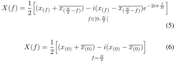
X(f ) = 1 2 h (x(f )+ x(N 2−f )) − i(x(f )− x( N 2−f ))e −2iπNfi f ∈[0,N 2[ (5) X(f ) = 1 2 h (x(0)+ x(0)) − i(x(0)− x(0)) i f =N 2 (6)
This process is very efficient, as it reduces the number of operations for an FFT of a real signal almost by half.
IV. ALGORITHM ANDOPTIMIZATION
A. Challenge
Algorithm: The main challenge is to parallelize efficiently the execution of the 219 FFT of real points over the 256 cores of the MPPA platform. Moreover, tests were made in order to find the best FFT algorithm. The selected algorithm is based on the Six-Step method performed in fixed-point arithmetic because it fits the SKA precision requirements and is more efficient on the MPPA processor.
Memory: The next challenge is fit this large FFT compu-tation inside one cluster; this enables to run 16 219 FFTs of real points in parallel, one per cluster. Each complex number is stored on an integer which means 16-bit for the real part and 16-bit for the imaginary part. Thus, the computation requires one Mega bytes to store the entire FFT data set thanks to formula (6) because the second half of the FFT is the complex conjugate of the first half computed with the 218 complex
point FFT. This implementation is able to fit inside one cluster which contains 1.7 Mega bytes of available local memory shared by the 16 application cores only if it is computed in-place (i.e the input is overwritten by the output as the algorithm executes). Such a compute configuration is required as the MPPA architecture is a Non-Uniform-Memory-Access, where the compute locality must be managed as effectively as possible. It means that bulk data transfers need to be limited to the streaming from/to the compute clusters of the MPPA. Memory copies and internal variables have to be reduced as much as possible.
B. In-Place Matrix Transposition in the Six-Steps Stage This matrix transposition is difficult to design to perform in parallel, given that it must be done in-place, without using auxiliary memory. The design is to swap half of the SMEM
content inside one cluster, balancing the work between each core and in such a way that cache misses are limited.
The matrix size that needs to be transposed is 512 ∗ 512 = 218 and the size of each complex number is 32-bit. In figure 2, each core PE that is actually in charge of transposing its memory area can be seen. Moreover, the following equation helps to understand how does the work is spread among the 16 cores inside one cluster:
218= 1Core∗ (32 ∗ 32)DiagonalBlock∗ 16N bBlock+
15Cores∗ [(32 ∗ 16) ∗ 2]U pperLowerBlock∗ 16N bBlock
(7)
Each core operates on the same amount of data and has exactly the same workload. Diagonal blocks are size of 32 ∗ 32 = 1024 complex numbers and upper and lower diagonal blocks are size of 16 ∗ 32 but work in pairs; therefore, it is 2∗16∗32 = 1024 complex numbers. This in-place transposition also enables a setup of the radix-point of the FFT values to be processed.
Fig. 2: In-Place Transposition Work Distribution Load balancing of an in-place matrix transposition is difficult as it requires to take into account the data cache size and the data layout of the memory area to be transposed. Our approach rearranges the data so that during the FFT stages, cache misses will be reduced significantly. This approach applies to any similar in-place matrix transposition problem. It is especially useful for embedded systems, as the on-chip memory is the most critical resource.
C. Fast Fourier Transform Six-Steps Stages
The main purpose of the Six-Steps method [8] is to break the FFT into smaller independent FFTs. However, several work configurations were investigated before selecting the one that best fits with the 16 cores of the MPPA compute cluster.
For this purpose, the input is interpreted as a matrix of 512 ∗ 512 and FFT computations are performed on 512 points.
The 512-point FFT implementation used is a Radix-4 [9] combined with a Radix-2 in another Six-Steps method. In order to compute it, only four stages of Radix-4 and one stage of Radix-2 are needed (as 44∗ 21= 512). All twiddle coefficients
required by the FFT computation formula are pre-computed and stored into the SMEM. Moreover the bit-reversal needed at the end of the FFT computation is performed with a look-up table in order to be done efficiently. There are no thread parallelization at this level but SIMD parallelism.
The embracing parallelism is found in the level of 512-point FFTs. 512-512-point FFTs are computed independently one from the other by the 16 cores and data are continuous in memory; therefore, there are almost no cache misses thanks to the matrix transposition and the data cache pre-fetching (Fig. 2). Each core has 32 512-point FFTs to compute and the work is embarrassingly parallel in one cluster.
D. Twiddle Correction Six-Steps Stage
The twiddle coefficients are pre-computed and stored in-side clusters because their computation would degrade the performance. In addition, we reduce the memory consumption inside one cluster by 15% by using 8-bit twiddle coefficients. The twiddle correction is performed in the same time as the second transposition operation. Overall, this reduces the memory accesses significantly and divides the computing time by 4.
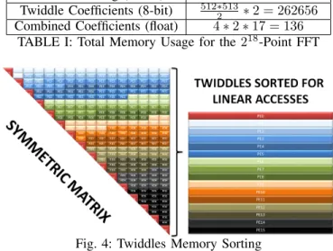
Those twiddle factors represent a symmetric matrix with the size of 512 ∗ 512. This means that only roughly half of the coefficients need to be stored. The challenge consisted in storing 512∗5132 twiddle coefficients in a smart way. This means that the reading of the pre-computed twiddle coefficients has to be as continuous as possible for each core when the core is doing the transposition operation on its blocks. It provides cores with homogeneous memory accesses when the twiddle coefficients are read. Moreover, it eases the use of the data cache pre-fetching.
E. Combine the N2 FFT Result
This process extracts the FFT result of the 219 input
samples by combining real and imaginary output samples of the 218 FFT with equations 5 and 6. In this process, twiddle factors are also needed and they need to be very accurate.
Thanks to those formulas, they can be easily computed using the complex number rotation multiplication in order to compute the next twiddle factor and so on. As 16 cores are available, only 16 twiddle factors need to be stored for each core. Then, the next twiddle factors are computed on the fly very accurately with the FPU. Moreover, this operation needs to be performed in-place and each core must have a balanced workload. Figure 3 shows how the memory accesses are made if we consider the following square block to be the result of our 218-complex-point FFT.
V. RESULTS
As the main challenge of this work is to fit a large 218 complex-point FFT into the SMEM of each MPPA compute cluster, memory results are listed with the associated needs. This sections also compares the final sequential algorithm to
Fig. 3: Real and Imaginary Combination Load Balancing
the parallelized algorithm, using the exact same test conditions in order to be fair. At the scope of one compute cluster, two levels of optimization are described: the 512-point fixed-point function, which can be implemented using different techniques, and the high level Six-Steps method parallelization using the MPPA POSIX-Level programming model.
A. Memory Design
In this section, we detail the memory usage within one clus-ter with regards to the Six-Steps implementation. The solution for storing the twiddle factors in the SMEM is shown in figure 4 (see twiddle colors for each working core). This solution can be applied to other architectures, as most of them behave better when linear memory accesses are made. For instance, data cache pre-fetching is enabled and memory addresses are better disambiguated by the compiler, thus optimizing the CPU use of the memory system capabilities.
Six-Steps Method Level Used Memory (Bytes) 218 FFT Storing (16-bit) 2 ∗ 2 ∗ 218= 1048576
Twiddle Coefficients (8-bit) 512∗5132 ∗ 2 = 262656 Combined Coefficients (float) 4 ∗ 2 ∗ 17 = 136
TABLE I: Total Memory Usage for the 218-Point FFT
Fig. 4: Twiddles Memory Sorting
The implementation of the adapted 4 with Radix-2 algorithm in a 51Radix-2-point Six-Steps FFT also requires pre-computed values that are stored in the SMEM.
The final required static space is 1.4 MB when considering program instructions. Thank to these memory optimization, the application is able to fit inside one MPPA compute cluster.
512-point Fixed-Point FFT Used Memory (Bytes) Bit reverse LUT (8-bit) 2 ∗ 256 = 512 FFT Twiddle Coeff. (16-bit) 2 ∗ 510 = 1020 Twiddle Corr. Coeff. (16-bit) 2 ∗ 2 ∗ 512 = 2048 TABLE II: Memory Usage for the Adapted 512-point FFT Function
B. 512-Point Fixed-Point FFT
This 512-point FFT is performed sequentially. There is no parallelization but use of SIMD operations. It is then executed by the 16 cores of the cluster in parallel. Each core is in charge of computing 32 512-point FFT as 512 = 16core∗32. To ensure
the functional safety, the fixed-point has been designed using the worst case of the 219 real input samples when the data
range increase during FFT stages. Current mathematical stud-ies provided this FFT fixed-point design with the theoretical most unlikely output of SKA receiver dishes.
Algorithm Timing (µs) 512-Point Radix-2 FFT 122 512-Point Radix-4/2 Six-Steps FFT 84
TABLE III: Radix-2 Vs an Optimized Radix-4/2 Mixed Using the Six-Steps Method
The 512-Point Radix-4/2 Six-Steps FFT is performed by interpreting the 512-point FFT as a matrix of 256 ∗ 2 and two 256-point FFT can be performed using a Radix-4 algorithm [9] for the first Six-Steps FFT stage. The second Six-Steps FFT stage is then performed using the 256 Radix-2 butterflies [4] with the Six-Steps twiddle correction stage in it.
C. Steps Timing of the218-Complex-Point Six-Steps FFT
For each step of the Six-Steps method, a function and a flow of data are given to each core. Work is balanced in order to have cores running for the longest amount of time in parallel. Six-Steps FFT (ms) Sequential Parallel Speed-Up
Transpose 9.19 0.77 11.93 512 512-point FFT 40.07 2.70 14.84 Trans. & Twid. Corr. 12.52 1.00 12.52 512 512-point FFT 40.07 2.70 14.84 Transpose 9.12 0.97 11.54 TABLE IV: Comparison Results Between the Parallel and Sequential Implementation for each Step
The speed-up between the sequential and parallel imple-mentation is efficient considering that the core 0 of clusters have to create and join the 15 POSIX threads [3]. For each step, 15 threads are created and the work of core 0 starts after the threads creation. Then, thread joins are performed and the steps of the Six-Steps method that follow are handled until the end. It enables a 218 complex FFT to be done in 7.94ms with
a global speed-up of 13.9 for the 16 cores running in parallel. D. Total 219-Real-Point FFT Timing
Timing tests have been made using DMA transfers in an asynchronous way to move one 219 real input sample set from the Input/Output Subsystem to one of the 16 clusters. The fastest DMA transfers are achieved by making bulk data transfers. Data rearrange steps are needed at the beginning and
the end of the FFT computation, because input and output data of a compute cluster are on 8-bit, while the computation is done on 16-bit fixed-point data to have the required accuracy. FFT Algorithm (ms) Sequential Parallel Speed-Up
Input Arrange − 0.67 − FFT Six-Steps 110.38 7.94 13.90 Combined Real & Im. 14.05 0.97 14.48 Output Arrange − 2.06 − TABLE V: Comparison Results in One Compute Cluster
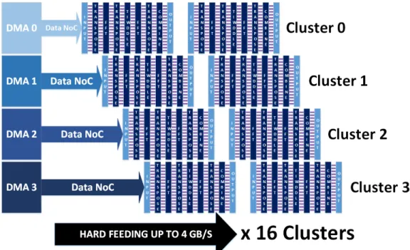
Considering input and output data of clusters to be trans-ferred with DMAs, the total fixed-point FFT implementation of the computation of 219real samples takes 11.69ms to be done in one cluster without taking into account DMA data transfers. The parallelization efficiency inside one cluster achieves up to 90% load and can be seen on the right part of figure 6. E. Application Feeding
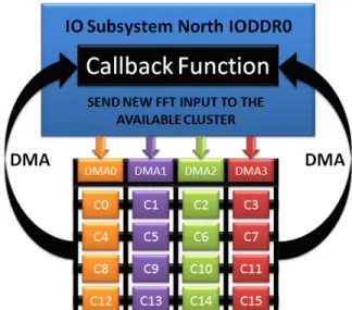
Each cluster can perform a 219 real fixed-point FFT in-dependently. Clusters need to be fed with data through the data NoC. Each cluster has its own binary executable and so does the IO Subsystem; therefore, 17 processes are running concurrently. The fastest way of sending 219real byte samples
is by asynchronous DMA transfers over the NoC, which are managed by dedicated µcores (top-left part of Fig. 5).
Fig. 5: Clusters Feeding With The IO Subsystem In this application (Fig. 5), for an IO Subsystem point of view, clusters are peripherals: whenever one cluster finishes to compute and delivers its FFT results, it triggers a signal and the IO Subsystem sends a new FFT set of samples to the cluster using very fast DMAs through the NoC.
In figure 6, the 16 clusters are fed from the IO Subsystem by asynchronous DMA transfers. The IO Subsystem embeds 4 DMA engines, each able to run up to 8 data transfer threads. F. Profiling & Power Consumption
The following table shows the results when different MPPA configurations are set:
Therefore, with 16 compute clusters, the computation time for one fixed-point FFT of 219 real byte samples can be
Fig. 6: Parallelization on all Compute Clusters Nb Clus. Transf. IO-Clus. (ms) FFT (ms) P. (W)
1 1.37 13.06 4.9
4 2.31 3.5 6.0
8 3.29 1.87 7.5 16 5.4 1.07 8.7 TABLE VI: MPPA Timing and Power Consumption Results
decreased down to 1.07ms with a power consumption of 8.7W (measured on the MPPA-256 board). The transfer (IO-Clus.) time is the sum of getting and sending back the FFT flow of data to compute.
A single-precision floating-point implementation running on a single core of an x86 CPU (Intel Core i7 3820 at 3.60 GHz with 10240 KB of cache memory) results in 228 ms and the fixed-point computation results in 78 ms in the same configuration. This x86 architecture has a typical power consumption of 80W, thus its number of FFTs is 0.16F F T /J . Regarding the MPPA, it is 107.42F F T /J , which corresponds to an energy efficiency improvement of 671x compared to the x86 reference implementation.
An implementation on the Exynos 5410 platform has been performed to compare our results with processors de-signed for embedded systems. Exynos is a series of ARM-based System-on-Chips (SoCs) developed and manufactured by Samsung Electronics. The octa-core Exynos 5410 platform is a big.LITTLE configuration with four ARM Cortex A7 cores running at 600 MHz and four ARM Cortex A15 cores running at 1.6GHz. This SoC is widely used for its low power capabilities to implement signal and image processing applications [10]. The CPU has a maximum clock frequency of 1600 MHz and can be scaled down to 250 MHz. The power dissipation of the ARM platform was measured by reading internal power registers in the SoC while running the application under evaluation. The registers contain values representing the dissipated power for the Cortex-A15, the
Cortex-A7 and for the external memory in Watts. All values can be read from user space when issuing calls to specific control registers which handle the measurement sensors. In this experiment, the code is implemented using a single ARM cortex core. Archi. FFT (ms) P. (W) Efficiency. (FFT/J) MPPA 1.07 8.7 107.42 x86 228 80 0.16 Cortex A7 1044 0.383 2.5 Cortex A15 473 1, 86 1.13
TABLE VII: Comparison of Timing and Power Consumption Results with other Architectures
VI. CONCLUSION& PERSPECTIVE
This work demonstrates that a parallel approach for com-puting large-scale FFTs on many-core platforms such as the Kalray MPPA-256 Andey processor with a POSIX-like process & threads programming model is effective. Applications need suitable algorithms that expose embracing parallelism in order to take advantage of such platforms. The Six-Steps method implementation we describe is able to exploit a high degree of parallelism across the FFT computations within each compute cluster of the MPPA processor. Parallel execution across the 256 cores decrease the processing time down the 1.07ms with a mean power consumption of 8.7W. The computation of the FFT is done in real-time following the requirements of the SKA project. Moreover the power efficiency of the proposed implementation is 671 times better than x86 solutions, 42.3 times better than Cortex A7 solutions and 95 times better than Cortex A15 solutions.
The FFT implementation we present targets the current SKA CSP (Central Signal Processor) project requirements. On-going discussions internal to this project consider increasing the FFT size in order to reduce the spectral leakage. Such evolution of the performance requirements could be met by
adapting our implementation to the second generation MPPA processor, code-named Bostan. This processor also integrates 256 VLIW application cores, but operates over 600MHz and has twice the energy efficiency of the MPPA Andey processor. Both processors are manufactured using the same TSMC CMOS 28HP (28nm) process, however the MPPA-256 Bostan VLIW cores perform twice as much fixed-point or floating-point operations per clock cycle. While our implementation fits well the MPPA architecture which features 16 cores per compute cluster, it appears flexible enough to be applied other multi-core architectures as well.
REFERENCES
[1] R. Ansari, “Cosmology: from fundamental questions to computing challenges,” in Paris-Saclay Center for Data Science Kick-off Meeting, Orsay, France, Jun. 2014. [Online]. Available: http: //hal.in2p3.fr/in2p3-01020026
[2] B. Carlson, “Ska csp internal requirements definition for chiplevel and chip memory level design and development start,” November 2013. [3] B. D. de Dinechin, P. G. de Massas, G. Lager, C. L´eger, B. Orgogozo,
J. Reybert, and T. Strudel, A Distributed Run-Time Environment for the Kalray MPPA-256 Integrated Manycore Processor, June 2013. [4] M. T. Heideman, D. H. Johnson, and C. S. Burrus, “Gauss and the
history of the fast fourier transform,” The ASSP Magazine, vol. 1, no. 4, pp. 14–21, October 1984.
[5] J. W. Cooley and J. W. Tukey, “An algorithm for the machine calculation of complex fourier series,” Math. Comput., vol. 19, no. 90, pp. 297–301, April 1965.
[6] Y.-T. Cheng, “Autoscaling radix-4 fft for tms320c6000,” March 2000. [7] B. Spinean and G. Gaydadjiev, “Implementation study of FFT on
multi-lane vector processors,” in 15th Euromicro Conference on Digital System Design, DSD 2012, Cesme, Izmir, Turkey, 2012, pp. 815–822. [8] D. H. Bailey, “Ffts in external or hierarchical memory,” J. Supercomput.,
vol. 4, no. 1, pp. 23–35, Mar. 1990.
[9] C. Wu, “Implementing the radix-4 decimation in frequency (dif) fast fourier transform fft) algorithm using a tms320c80 dsp,” January 1998. [10] E. Nogues, R. Berrada, M. Pelcat, D. Menard, and E. Raffin, “A dvfs based hevc decoder for energy-efficient software implementation on embedded processors,” in Multimedia and Expo (ICME), 2015 IEEE International Conference on. IEEE, 2015, pp. 1–6.