O
pen
A
rchive
T
OULOUSE
A
rchive
O
uverte (
OATAO
)
OATAO is an open access repository that collects the work of Toulouse researchers and
makes it freely available over the web where possible.
This is an author-deposited version published in :
http://oatao.univ-toulouse.fr/
Eprints ID : 12035
To link to this article : DOI :
10.1109/EuCAP.2014.6902078
URL :
http://dx.doi.org/10.1109/EuCAP.2014.6902078
To cite this version :
Pascaud, Romain and Pizarro, Francisco and
Pascal, Olivier and Callegari, Thierry and Liard, Laurent
Theoretical and numerical study of a plasma-based frequency
tunable microstrip antenna. (2014) In: 8th European Conference on
on Antennas and Propagation, EuCAP 2014, 6 April 2014 - 11 April
2014 (The Hague, Netherlands)
Any correspondance concerning this service should be sent to the repository
administrator:
[email protected]
Theoretical and Numerical Study of a Plasma-Based
Frequency Tunable Microstrip Antenna
Romain Pascaud
1, Francisco Pizarro
1, Olivier Pascal
2, Thierry Callegari
2, Laurent Liard
21Universit´e de Toulouse, ISAE, DEOS, Toulouse, France, Email: [email protected]. 2Universit´e de Toulouse, CNRS, UPS, INP, LAPLACE, Toulouse, France.
Abstract—The use of a plasma microdischarge as a reconfig-urable element for a frequency tunable microstrip antenna is theoretically and numerically investigated.
Index Terms—microstrip antennas, reconfigurable antennas, plasma devices.
I. INTRODUCTION
Frequency tunable antennas have been widely studied to cope with the increasing number of communication stan-dards [1]. They usually integrate active lumped elements (e.g. PIN diodes, RF MEMS, ...) or reconfigurable materials (e.g. ferrites, liquid crystals, ...) to allow control of their instantaneous bandwidth. Most of these solutions, however, cannot be used when medium to high microwave power is in-volved. Therefore, the use of plasma discharges as microwave reconfigurable elements is currently investigated because of their ability to handle microwave power [2].
Reconfigurable plasma antennas usually rely on large vol-umes of plasma confined in glass tubes to modify their resonant frequencies or to shape their radiation patterns [3]. Despite of the recent advances in microplasmas [4], few re-configurable microstrip devices using localized microplasmas have been proposed [5].
In this paper, we theoretically and numerically investigate the feasability of a plasma-based frequency tunable microstrip antenna.
II. COLDPLASMAS A. Physical Characteristics
A plasma is an ionized gas, macroscopically neutral. To generate a plasma discharge, one must provide enough energy to a neutral gas so that its ionization degree reaches a level that changes its macroscopic properties from an insulator to a conducting medium.
A common way to create a plasma is to apply a voltage between two electrodes in the gas. It leads to a non-equilibrium or cold plasma where the heavy particles keep their temper-ature close to the room tempertemper-ature while the electrons are heated enough to cause ionization by collision with neutrals.
B. Electromagnetic Model of a Homogeneous Cold Plasma
From an electromagnetic point of view, a homogeneous cold plasma can be modeled as a dielectric medium whose complex
relative permittivity ϵp is given by [3]:
ϵp = ϵr(1− j tan δ) = ( 1− ω 2 p ω2+ ν2 p )( 1− jνp ω ω2 p ω2+ ν2 p− ω2p ) (1) where ω represents the angular frequency of the electromag-netic wave interacting with the plasma, νpthe plasma
electron-neutral momentum transfer frequency, or collision frequency, and ωp the electron plasma angular frequency defined as:
ωp=
√
nee2
ϵ0me
(2) with e the electron charge, ϵ0 the permittivity of vacuum, and
methe electron mass.
According to Equations (1) and (2), we can see that the dielectric constant ϵrof a homogeneous cold plasma medium
can be controlled by varying its electron density ne and
collision frequency νp. Besides, it is interesting to notice that,
for a given angular frequency ω, the dielectric constant ϵrcan
be negative, null, or positive with a value between 0 and 1. III. CAVITYMODELANALYSIS OF APLASMA-LOADED
RECTANGULARMICROSTRIPANTENNA A. Description of the Cavity Model Analysis
The cavity model technique is often used to estimate the resonant frequencies of a microstrip antenna [6]. It consists in modeling the antenna as a cavity bounded by two PEC conditions above and below it, and PMC conditions along its perimeter. Here, we consider a rectangular cavity completely filled with a homogeneous cold plasma medium. Its resonant angular frequency ωres for the fundamental TM10 mode is thus given by:
ωres= cπ L√ϵr = cπ L √ 1− ω2p ω2 res+νp2 (3)
If we assume that the plasma is generated so that its dielectric constant is positive (i.e. 0 < ϵr < 1), we finally
obtain the following biquadratic equation for ωres:
ω4res+ ( νp2− ωp2− c2π2 L2 ) ω2res− (cπν p L )2 = 0 (4) that has four solutions, one of which is purely real and positive. This latter solution represents the resonant angular frequency
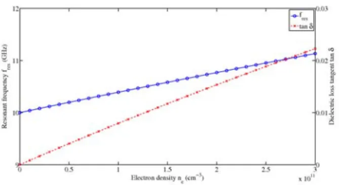
Fig. 1. Resonant frequency (TM10mode) of the cavity filled with a
homo-geneous plasma as a function of the electron density (νp= 6.5× 10⁹s−1).
B. Results of the Cavity Model Analysis
In this study, we have considered a plasma discharge gen-erated in a mix of Neon-Xenon at 5 torr which leads to an approximated collision frequency νp = 6.5× 10⁹ s−1 and a
maximum electron density ne= 3× 1011 cm−3.
Figure 1 presents the resonant frequency fres calculated
thanks to Equation (4) as a function of the electron density. We observe that the resonant frequency of the cavity increases almost linearly with the electron density. Therefore, one may theoretically control the resonant frequency of the cavity by varying the plasma electron density. However, as it is also shown in Figure 1, increasing the electron density ne results
in a larger dielectric loss tangent tan δ of the plasma medium. IV. NUMERICALANALYSIS OF APLASMA-LOADED
RECTANGULARMICROSTRIPANTENNA A. Plasma-Loaded Inverted Microstrip Antenna
Several numerical simulations have been carried out with Ansys HFSS. Figure 2 shows the simulated antenna. It consists of an inverted microstrip antenna loaded by a homogeneous cold plasma. The inverted microstrip antenna is a rectangular element printed on a dielectric substrate with ϵr = 3.5 and
tan δ = 0.0018. Its dimensions are L = 11.35 mm and
W = 18 mm so that it is well matched at its resonant
frequency of 10 GHz. This antenna is fed with a 50 Ω inverted microstrip transmission line (Wline = 3.3 mm). Due to this
inverted configuration, an air gap of 1 mm is present between the ground plane and the dielectric substrate that supports the antenna. The plasma medium is finally located in this space. It has the same length L and width W as the microstrip antenna, but its height is slightly lower (hplasma = 0.8 mm) to take
into account of the plasma sheaths that appear between the plasma discharge and the conductors of the antenna [5].
B. Results of the Numerical Analysis
Figure 3 presents the simulated |S11| parameters of the plasma-loaded inverted microstrip antenna as a function of the frequency and the electron density of the plasma (νp =
6.5× 10⁹ s−1). We notice that the resonant frequency of the antenna increases with the electron density. A shift of
Fig. 2. Plasma-loaded inverted rectangular microstrip antenna.
Fig. 3. Simulated|S11| of the plasma-loaded inverted microstrip antenna
as a function of the frequency and for different electron densities (νp =
6.5× 10⁹s−1).
400 MHz (i.e. 4 % of the initial resonant frequency) is observed when ne = 3× 1011 cm−3. This shift is lower
than the one predicted by the cavity model analysis. This difference may be explained by the inverted configuration which is slightly different from the classical microstrip antenna and its cavity model.
V. CONCLUSION
We have theoretically and numerically investigated the feasability of a plasma-based frequency tunable microstrip an-tenna. Thorough study as well as achieved simulated antenna gain will be presented and discussed during the conference.
Current work focuses on the development and characteriza-tion of a plasma-based frequency tunable microstrip antenna.
REFERENCES
[1] A. Petosa, “An Overview of Tuning Techniques for Frequency-Agile Antennas,” IEEE Antennas Propag. Mag., Vol. 54, No. 5, pp. 271-296, Oct. 2012.
[2] F. Pizarro, R. Pascaud, O. Pascal, T. Callegari, and L. Liard, “Experi-mental study of RF/microplasma interaction using an inverted microstrip line,” in Proc. 7th Eur. Conf. Antennas Propag. (EuCAP), Apr. 2013, pp. 1187-1190.
[3] T. Anderson, Plasma Antennas, Artech House, 2011.
[4] K. H. Becker, K. H. Schoenbach, and J. G. Eden, “Microplasmas and applications,” J. Phys. D Appl. Phys., Vol. 39, No. 3, pp. R55, Feb. 2006. [5] P. Linardakis and G. G. Borg, “Small-Signal Impedance of a Radio Frequency Plasma Capacitor,” IEEE Microw. Wireless Compon. Lett., Vol. 17, No. 11, pp. 763-765, Nov. 2007.
[6] P. Bhartia, I. Bahl, R. Garg, and A. Ittipiboon, Microstrip Antenna Design