To cite this document: Vongsantivanich, Wasanchai and Defay, Francois and Bérard, Caroline Multi-level fine pointing test-bed for space applications. (2012) In: Small Satellites Systems and Services - The 4S Symposium 2012, 04-08 Jun 2012, Portorož, Slovenia.
O
pen
A
rchive
T
oulouse
A
rchive
O
uverte (
OATAO
)
OATAO is an open access repository that collects the work of Toulouse researchers and makes it freely available over the web where possible.
This is an author-deposited version published in: http://oatao.univ-toulouse.fr/ Eprints ID: 6280
Any correspondence concerning this service should be sent to the repository administrator: staff-oatao@inp-toulouse.fr
MULTI-LEVEL FINE POINTING TEST-BED for SPACE APPLICATIONS
Wasanchai Vongsantivanich(1), Franc¸ois Defa¨y(2), Caroline Berard(3)
(1),(2),(3)Institut Sup´erieur de l’A´eronautique et de l’Espace (ISAE)
Department of Mathematics, Computer Science and Control
Email : w.vongsantivanich@isae.fr, francois.defay@isae.fr, caroline.berard@isae.fr
ABSTRACT
For space applications that need high accuracy pointing of the payload, fine pointing system is an indispensable tool. To reach high level of high accuracy pointing and tracking, proper synchronization between the attitude of the satellite and each stage of the pointing module should be considered. This study focuses on developing and demonstrating staging control for fine pointing system. Currently, an experimental model for multi-stage control has been built in the laboratory to be used as a testbed and a teaching tool to validate the control strategies. This paper gives a brief introduction of the study, experimental model design criteria and staging control strategy. An example of a controller synthesis for multi-stage actuators based on H∞is also presented.
INTRODUCTION
Fine pointing mechanism (FPM) is a sub-system in spacecraft which contains group of actuators, sensors working together in order to achieve high precision pointing attitude control for various types of payloads. The capability to point and track with high precision is an essential requirement for many types of space missions. For example, in case of laser optical telecommunication terminal between ground-space or space-space [9], formation flying interferometer [7], remote sensing satellites or exoplanet observation [10].
Despite there are various types of high precision actuators currently available in the industry, it is still not possible to achieve fine pointing and tracking performance requirements by using only single actuator. This is due to the fact that each actuator resolution, saturation level and operation bandwidth are limited. From this reason, multiple actuators are needed to be combined and synchronized in an appropriate way in order to satisfy high precision goals. From literature reviews, most of the researches on multi actuator precision pointing control are dedicated to the control of hard disk drive write head servo mechanism. For hard disk drives, in order to have higher data density, the read-write head must be able to search and follow very narrow data tracks (≈ 1µm [3]). Dual-stage control with voice coil motor (larger travel range, slower response, lower accuracy) as a primary actuator and a complement piezo actuator (shorter range, faster response, higher accuracy ) connected in series is widely used for this type application. Moreover, applications of multi-stage actuators are also found in those ultra high precision alignment machine in the semiconductor industry [6], camera stabilization system [11], positioning - feeding manipulators [5], [14] and opto-mechatronic system [13].
For the framework of this study, we present an experimental testbed that is built in the laboratory in order to demonstrate staging control strategies. Assume a space mission for small satellite that
fine pointing and orientation of the payload is one of the requirement ; ex. exoplanet observer cam-era, laser communication terminal, etc. ; where attitude of the satellite can be adjusted to maintain pointing orientation. In this case, it is possible to use the attitude control of the satellite itself as a coarse actuator where another finer, faster actuator works in complement to suppress disturbances or vibrations caused by environment or other payloads.
To demonstrate this proposed system, a friction-free rotary platform with a reaction wheel is used to represent a satellite and its attitude control system. A voice coil motor (VCM) is mounted on top of the platform to be the fine pointing actuator. More details are given in the following section.
TESTBED MODEL
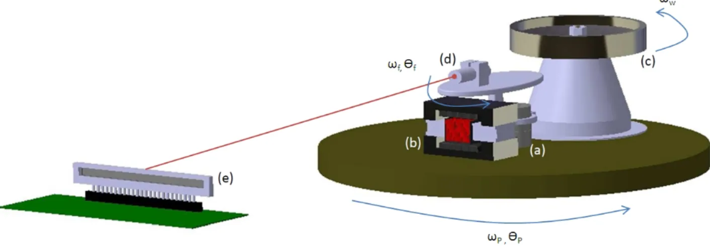
The experiment model is designed as a testbed to demonstrate multiple types of fine-pointing strategy for space applications (the model is shown in figure 1). In the first phase of this study, staging control will be demonstrated by using a reaction wheel as a coarse actuator and a VCM is used as a fine pointing actuator. Laser module is then fixed on the fine pointing actuator to represent the payload. Linear array sensor is used to detect the laser position to get the system feedback. Design consideration for each components are as followings;
Figure 1: Experimental model (a) Pivot bearing; (b) VCM; (c) Inertia wheel; (d) Laser module; (e) Linear array sensor
• Reaction wheel : The coarse pointing state is done by using the transfer of momentum from a reaction wheel. This wheel will be driven by 24V brushless DC motor.
• Pivot bearing : Preloaded pivot bearing is used in the system as an axis of the fine pointing state in order to overcome the friction force. When idle, the fine pointing actuator has to coun-teract the spring torsion load from this bearing. The size of the pivot bearing has to be chosen according to available actuator torque since too large counteracting torque will result in poor control response. In this model, the preloaded bearing has a torsional spring rate of 0.37 Nm. • Voice Coil Motor (VCM) : VCM is a kind of DC motor that consists of the coil (attached to the
movable load) that moves in magnetic field. VCM is chosen as a fine pointing actuator for this testbed because its high resolution of micro-radian scale (the resolution also depends mainly on quantization of the actuator input from the controller). VCM has an advantages of its ease of controlling as its torque is directly proportional to the current in the coil. In comparison with piezoelectric actuator or magnetic actuator, VCM also gives longer stroke. In this experiment,
the voice coil actuator must capable of generating sufficient torque to counteract the pivot bear-ing. The VCM that is selected has the peak torque at 1.85 Nm with 0.798 Nm continuous torque with no backlash and low hysteresis effect. Its travel angle is ± 3.75◦.
• Laser module : Laser diode is used to indicate the pointing direction. Red light laser with 700 nm wavelength was chosen for this experiment since it is the visible wavelength that is closest to the peak of photodiode spectral responsitivity.
• Linear Array Sensor : The optical sensor array is used to acquired the feedback of the fine pointing. The sensor array selected to use in this experiment is a 1280 x 1 pixel optical sensor array with 400 dpi resolution (63.5 m pixel center-to-center spacing). According to the output voltage of the sensor given in equation 1.
Vout = Vdrk+ (Re)(Ee)(tint) (1)
where Vdrk is an output voltage when there is no light on the sensor, Reis the device sensitivity
for a given light wavelength, Ee is the incident irradiance and tint is integration time for the
sensor to collect light on each pixel. According to this relation, with our current laser power and model setup which the position detection is done through an analogue threshold detection circuit, the sensor sampling time (function of tint) could be reduced to 0.2ms. With respect to
the pixel size, the angular resolution of the sensor can be calculated. The sensor is located at 5m from the model, the angular resolution that can be detected will be ≈ 3 arcseconds.
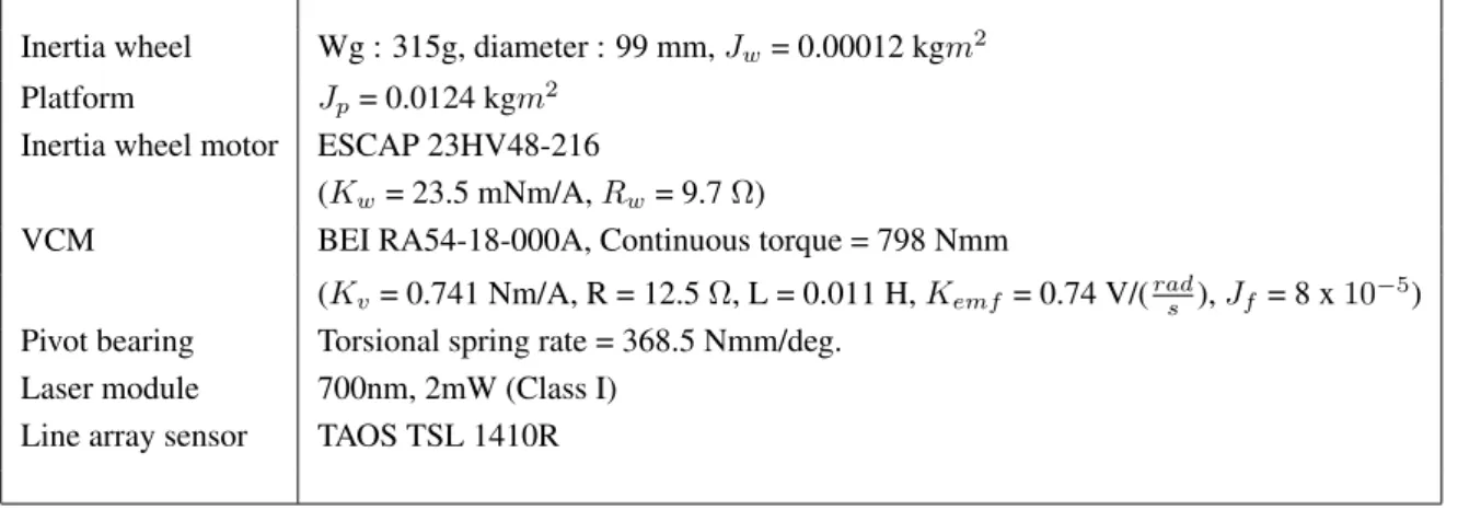
Inertia wheel Wg : 315g, diameter : 99 mm, Jw= 0.00012 kgm2
Platform Jp= 0.0124 kgm2
Inertia wheel motor ESCAP 23HV48-216
(Kw= 23.5 mNm/A, Rw= 9.7 Ω)
VCM BEI RA54-18-000A, Continuous torque = 798 Nmm
(Kv= 0.741 Nm/A, R = 12.5 Ω, L = 0.011 H, Kemf = 0.74 V/(rads ), Jf= 8 x 10⁻⁵)
Pivot bearing Torsional spring rate = 368.5 Nmm/deg. Laser module 700nm, 2mW (Class I)
Line array sensor TAOS TSL 1410R
Table 1: Components list
SYSTEM MODELING
The model is integrated according to the diagram in figure 1. A DC motor rotor is connected to the reaction wheel and spins it with an angular velocity ωw. An angular momentum Lw created by the
reaction wheel is then transfered to the platform and makes angular displacement θp with angular
velocity ωp. This platform angular displacement is measured by a potentiometer mounted on the axis.
Next, a voice coil motor with laser pointer on top is fixed on top of the platform. It moves the pointer module with an angular velocity ωf and an angular displacement θf. The laser pointer is
pointing toward the array sensor which measures angular displacement output of the system. The measurement by the array sensor is θ = θp + θf.
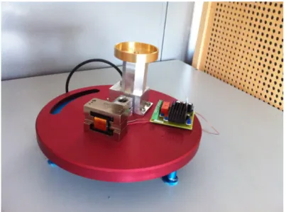
Figure 2: Model built in the laboratory
Hence, the system can be separated into two parts, the coarse pointing which is done through the movement of the platform due to the reaction wheel and the fine pointing by the VCM. The diagram of the coarse pointing can be shown as in 3. Rw, Lw, Kw are the motor parameters for resistance,
inductance and torque constant respectively. V is the motor voltage input, Jw is the inertia of rotor
axis with inertia wheel and Jp is the inertia of the platform.
Figure 3: Coarse pointing actuator
Fine pointing is done by VCM actuator. The dynamic equation for fine pointing can be expressed in equation 2.
Jfθ¨f = Tf − Tp (2)
where Jf is the inertia of the moving part of the VCM attached with laser pointing module; Tf is
the torque from VCM actuator and Tp is the counteract torque from preloaded pivot bearing. In this
case, as the model consist of preloaded bearing, the torque friction could be neglected. The electrical model of the VCM can be expressed in equation 3.
VV CM = RIf + LfI˙f + em (3)
where VV CM is the voltage input to the coil, If is the coil current, Lf is the coil inductance and
emis the back electromotive force which is proportional to the angular rate with constant. The torque
produced by VCM can be written as Tf = KfI.
Figure 4: Fine pointing actuator (VCM)
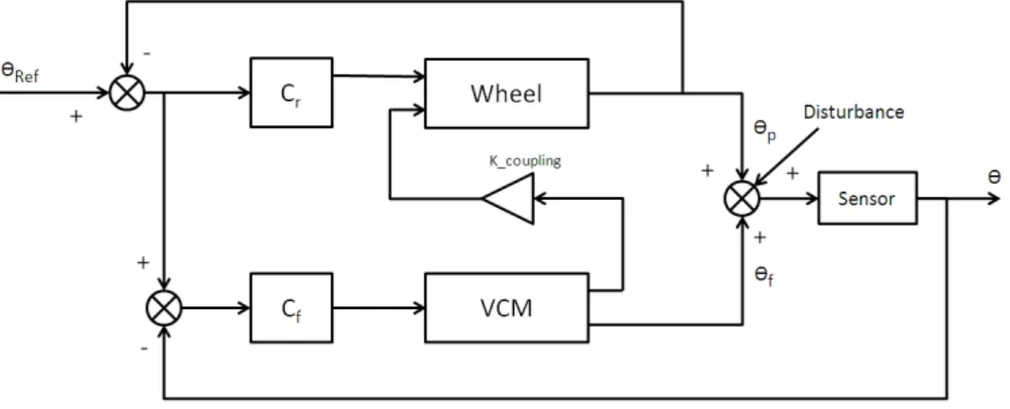
In this model, two measurements, θ and θp are available for the feedback. Therefore, feedback
loop can be provided on each actuator. Since the VCM is mounted on top of the platform, the move-ment introduced by VCM will have some coupling effect on the platform which is needed to be identified. The block diagram with controllers Cc, Cf can be shown as in figure 5.
Figure 5: Closed loop control with two feedbacks
CONTROL CONFIGURATION
The objective of this study is to implement staging control in order to minimize tracking error. The baseline strategy is to use coarse pointing state to primarily track the angular reference while the fine pointing helps to compensate the perturbation and error in the high resolution and high frequency bandwidth zone.
Researches on controlling of multi-stage actuators have been conducted continuously in this decade. Numbers of control strategies had been reported. [12], [8] had reviewed conventional ap-proaches to design cascade controllers based on on diverse configurations where each controller is defined based on the the shape of their frequency characteristics. Observer based LQR/LQG con-troller for dual-stage servo control had been introduced in [4]. Another approach which has been recently developed is the composite nonlinear feedback control which can be seen in [14].
For this paper, the H∞loop shaping controller design technique is chosen, since its ease to ensure
the close-loop robustness. An example of H∞ loop shaping for dual-stage actuator can be found in
[1]. In addition to classical H∞ approach, the newly developed fixed structure H∞ synthesis [2] is
used in this study with helps of the toolbox hinfstruct() in MATLAB. By this approach, the structure of the controller resulting from H∞synthesis can be defined which makes implementation
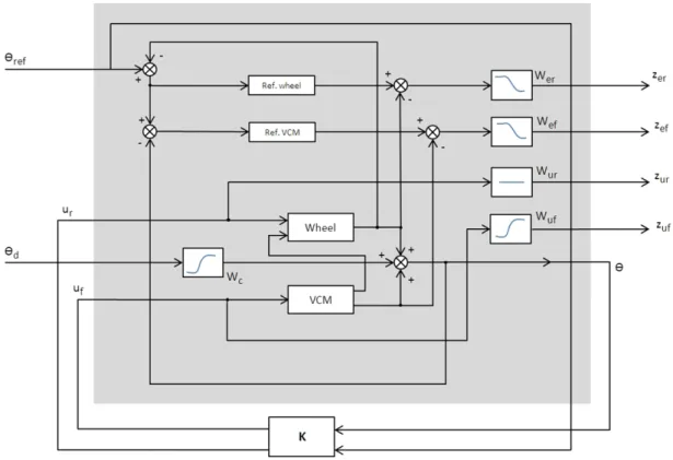
For the guideline of controller design, the model for H∞ analysis is shown in figure 6. Two
exogenous input θr and θc with four exogenous outputs zer, zef, zur and zuf are augmented into the
system. Reference models for coarse and fine actuators are used to help in angular position tracking for each actuator loop where zer, zef outputs are weighted in order to penalize the errors between the
reference and actual outputs.
Weighing filter Wcis shaped as a high pass filter and placed on the disturbance input to attenuate
the low frequency disturbances. zur, zuf outputs are used to weight the control input for the coarse
stage actuator (reaction wheel) and the fine stage actuator (VCM) respectively. Wur and Wuf are
placed to define frequency separation between each actuator. In this case, Wuf is a high pass filter
since the attenuation at low frequency should be set according to the objective that the VCM should response in the high frequency. For the coarse actuator, as its dynamic is already slow, the shape of Wuris set as a constant.
Figure 6: Augmented system with weighing functions for H∞analysis.
SIMULATION
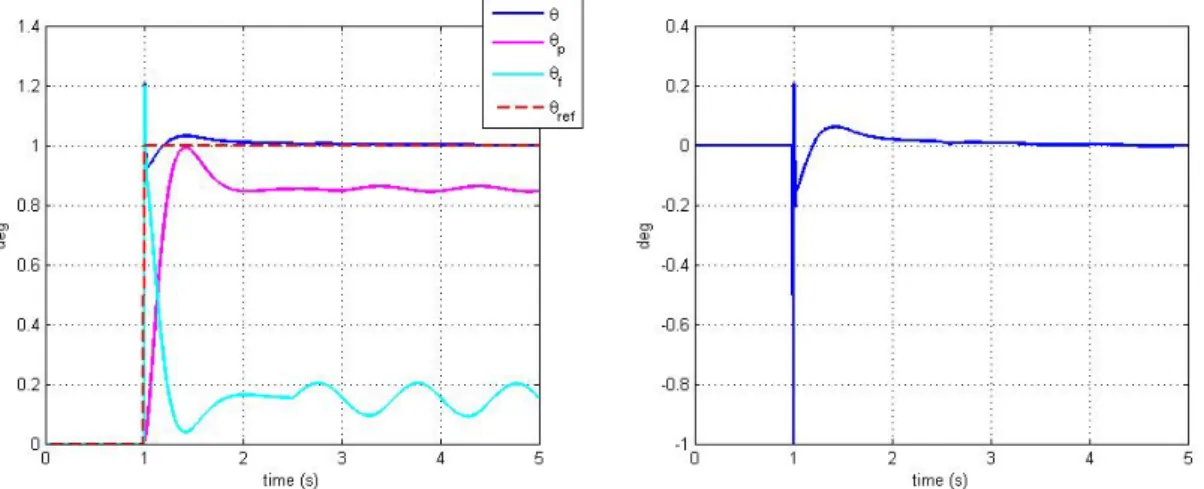
In this first stage, as the testbed is still not fully integrated, the reaction wheel and VCM model for simulation was set based on the available parameters (see table 1). The weighing filters were set as, Wc = 0.5s+10.3s+1, Wuf = 0.5s+125s+0.1 . Figure 7 shows the response of the system to step input. In term of
disturbance rejection, a sinusoidal disturbance signal sin(2πt) is fed into the system, started at t = 2.5. The response shows that the fast response of the fine actuator helps the system in reducing the rise time (as fast as the speed of VCM) and helps the system to reject disturbance. However, there still rest some effects of overshoot. From this simulation case, when effected by disturbance, the system could keep the bound of the error as low as 0.002 deg.
Figure 8 shows the response of the system with the mixed sinusoidal reference input of 2sin(t) + 0.2sin(10πt). It can be seen that the reaction wheel mainly tracks the low frequency reference where VCM follows the higher frequency.
Figure 7: Left: System and actuators response to step input (tr = 0.003 s), Right: Error from step
response
Figure 8: Response to sinusoidal input CONCLUSIONS AND FUTURE WORKS
This paper gives the details of the testbed for multi-stage control for space application. A guideline on controller synthesis based on H∞loop shaping is presented and simulation result is shown. Currently,
the testbed model is being built in the laboratory. After the testbed model is completed, the simulation will be validated by experiment result. This model will be used as a teaching tool in the laboratory. In the future, multiple testbeds with the same type platform will be developed in order to illustrate further control designs (ex. centralized, decentralized) problem.
Acknowledgment
The author would like to acknowledge Jean-Franc¸ois Dassieu and Eric Metral (DMIA team) for their support on the testbed parts fabrication.
REFERENCES
[1] U. Boettcher, R. A. de Callafon, and F. E. Talke. Data based modeling and control of a dual-stage actuator hard disk drive. Joint 48th IEEE Conference on Decision and Control, 2009.
[2] P. Gahinet and P. Apkarian. Structured H∞Synthesis in MATLAB. 18th IFAC World Congress,
2011.
[3] G. Guo, A. A. Mamun, and C. Bi. The Hard Disk Drive Mechatronics and Control. CRC Press, 2006.
[4] W. Guo, L. Yuan, L. Wang, G. Guo, T. Huang, B. M. Chen, and T. H. Lee. Linear Quadratic Optima Dual-stage Servo Control Systems for Hard Disk Drives. IEEE, 1998.
[5] S. Kwon, W. K. Chung, and Y. Youm. On the Coarse/Fine Dual-Stage Manipulators with Robust Perturbation Compensator. IEEE, 2001.
[6] C.-W. Lee and S.-W. Kim. An ultra precision stage for alignment of wafers in advanced mi-crolithography. Elsevier, Precision Engineering, 1999.
[7] K.-C. Liu and D. W. Miller. Stochastic performance analysis and staged controller designs for space interferometry systems. Proc. SPIE 4852, 556, 2003.
[8] A. A. Mamun, I. Mareels, T. Lee, and A. Tay. Dual Stage Actuator Control in Hard Disk Drive - A Review. IEEE, 2003.
[9] G. G. Ortiz, S. Lee, and J. W. Alexander. Sub-microradian Pointing for Deep Space Optical Telecommunications Network. In 19th AIAA International Communications Satellite Systems Conference, Toulouse, France, pages 1–16, 2001.
[10] C. M. Pong, S. Lim, M. W. Smith, D. W. Miller, J. S. Villasenor, and S. Seager. Achieving high precision pointing on ExoplanetSat: initial feasibility analysis. Proc. SPIE 7731, 77311V, 2010. [11] M. Rezac and Z. Hurak. Structured MIMO H∞ Design for Dual-Stage Inertial Stabilization :
Case Study for HIFOO. World Congress, Volume 18, Part 1, 2011.
[12] T. Semba, T. Hirano, J. Hong, and L.-S. Fan. Dual-stage servo controller for HDD using MEMS microactuator. Magnetics, IEEE Transactions, 1999.
[13] M. Stalder, Y. Michellod, P. Mullhaupt, and D. Gillet. Dedicated controller design for a dual-stage opto-mechatronic system. International Conference on Advanced Intelligent Mechatron-ics, IEEE/ASME, 2008.
[14] J. Zheng, A. Salton, and M. Fu. Design and control of a rotary dual-stage actuator positioning system. Mechatronics, 21(6):1003–1012, 2011.