To cite this version :
Chinaud, Maxime
and Rouchon, Jean-François
and Duhayon, Eric
and Scheller, Johannes
and Cazin, Sébastien
and Marchal, Moise
and Braza, Marianna
Trailing-edge dynamics and morphing of a
deformable flat plate at high Reynolds number by time-resolved PIV.
(2014) Journal of Fluids and Structures, vol. 47 pp. 41-54. ISSN 0889-9746
O
pen
A
rchive
T
OULOUSE
A
rchive
O
uverte (
OATAO
)
OATAO is an open access repository that collects the work of some Toulouse researchers
and makes it freely available over the web where possible.
This is an author’s version published in :
http://oatao.univ-toulouse.fr/11251
Official URL :
http://dx.doi.org/10.1016/j.jfluidstructs.2014.02.007
Any correspondence concerning this service should be sent to the repository administrator :
Trailing-edge dynamics and morphing of a deformable flat
plate at high Reynolds number by time-resolved PIV
M. Chinaud
a,b, J.F. Rouchon
b, E. Duhayon
b, J. Scheller
b,a,n, S. Cazin
a,
M. Marchal
a, M. Braza
aaInstitut de Mécanique des Fluides de Toulouse (IMFT), UMR CNRS-INPT-UPS No. 5502, Alleé du Prof. Camille Soula,
F-31400 Toulouse, France
bLaboratoire Plasma et Conversion d'Energie (LAPLACE), UMR CNRS-INPT-UPS No. 5213, 2 Rue Charles Camichel, F-31071 Toulouse, France
a r t i c l e
i n f o
Keywords: Morphing
Shape memory alloys Turbulence Aerodynamics Shear layer Von-Kármán instability Time-resolved PIV
a b s t r a c t
The present paper investigates the turbulent wake structure in the near-region past the trailing edge of a deformable inclined plate. The plate is actuated by shape memory alloys. Using these actuators a significant deformation (bending) can be achieved ( ! 10% of the chord) under the aerodynamic loads corresponding to a Reynolds number of 200 000. The shear-layer dynamics as well as the mean velocity and turbulent stresses have been quantified for a reference case (flat plate inclined at 101). The present study investigates the modification of the shear-layer and near-wake dynamics achieved by means of the dynamic deformation of the plate compared with static cases that include three intermediate positions of the deformed plate. The comparison of the static cases with the dynamic regime discusses the validity of the quasi-static hypothesis for the present low frequency actuation. It is found that the present actuation enhances the shearing mechanisms past the trailing-edge and modifies the von-Kármán mode as well as the structure of the shear-layer, Kelvin–Helmholtz eddies. Moreover, the increase of the bending enhances the appearance of the pairing mechanism between successive shear-layer eddies and the interaction between the von-Kármán and shear-shear-layer instability modes. Furthermore, it has been found that the increase of the plate's curvature leads to an attenuation of the shear-layer amplitude and of the overall spectral energy, concerning the most deformed position.
1. Introduction
Conventional fixed wing airfoil geometries are usually the result of a design compromise that aims at optimizing the shape only for selected parts of the mission profile. Control surfaces, while modifying the aerodynamic profile of the wing and thereby extending the mission profile, are usually characterized by poor aerodynamic performance and efficiency (Ursache et al., 2007). Adaptive, morphed structures hold the potential to solve this problem and for this reason morphing has appeared as a priority item in important strategies including the ‘FP7’ and ‘HORIZON 2020’ vision of the European
commission aeronautics research (Commission, 2012a,b. Therefore, studies on wing deformation receive considerable
http://dx.doi.org/10.1016/j.jfluidstructs.2014.02.007
n
Corresponding author at: Institut de Mécanique des Fluides de Toulouse (IMFT), UMR CNRS-INPT-UPS No. 5502, Alleé du Prof. Camille Soula, F-31400 Toulouse, France.
E-mail addresses:[email protected](M. Chinaud),[email protected](J.F. Rouchon),[email protected](E. Duhayon),
interest in the aerospace domain. Recent advances in the field of smart-materials have renewed this interest (Weisshaar, 2013;Valasek, 2012;McGowan et al., 1998).
A variety of smart-materials and actuators have been studied for morphing applications amongst which are piezoelectric materials (Hall and Prechtl, 1999;Straub et al., 2004), shape-memory alloys (SMAs) (Jänker et al., 2006;Thill et al., 2008;
Huang et al., 2010;Hartl and Lagoudas, 2007) and ferromagnetic shape-memory alloys (FSMAS) (Lagoudas, 2008;Sutou et al.,
2004) to name a few (Cadogan et al., 2003). The ‘Laboratoire Plasma et Conversion d'Energie’ (LAPLACE) developed for example
a piezoelectricPUSH–PUSHamplification mechanism based on piezoelectric stack actuators (Chinaud et al., 2013). This paper
will focus on actuation by SMAs. SMA materials are able to achieve large deformations at low actuation frequencies
(several Hz). For the last few decadesSMAtechnology was intensively studied and is now well understood from a structural
point of view. SMASs have many applications in the industry including medical and aerospace (Kakubari et al., 2003;Song and Ma, 2007). The characteristics of this actuator make it especially suitable to optimize the shape of the wing and to control the flight in order to increase aerodynamic performance. TheSMAactuators are activated in this study using the Joule
heating. This mechanism is well understood and was for example implemented by Barbarino and Manzo in order to modify the shape of an airfoil. Whereas Barbarino focussed on chordwise bending of an airfoil usingSMAwires (Barbarino et al.,
2009) and rods (Barbarino et al., 2010),Manzo (2006)appliedSMAactuators in a pulley mechanism in order to deform the
wing in the spanwise direction.Senthilkumar et al. (2013)usedSMAsprings in order to control the trim of an airfoil. The
developedSMAspring actuator achieved a displacement of 311 ( ! 16 mm) during wind-tunnel tests of the airfoil. Similarly
Brailovski et al. (2010)implementedSMAsprings under the skin of an airfoil in order to the change the camber.Strelec et al.
(2003)showed that by correct positioning of singleSMAwires a modification of the lift coefficient of the order of 0.03–0.05
can be achieved. Faria provided an accurate model of the behavior ofSMAactuated airfoils on the example of an airfoil made
out of individual segment linked by rotational joints. The developed model was capable topredict the deformation of the airfoil yet the hysteresis effect of theSMAs was an issue (Faria et al., 2012). This issue was addressed in a recent article by
Chinaud who demonstrated that the resistance of the wire is an accurate control parameter (Chinaud et al., 2012). Similar results were found by Lan who additionally investigated the pre-stress dependence on the accuracy of the control parameter. His results showed that by applying proper pre-stress the positioning error due to hysteresis can be reduced to 3%. The majority of these studies focus on the structural aspects of theSMAactuation. There exists little knowledge regarding
the fluid-mechanic and aerodynamic behavior ofSMAactuated structures.
The present paper aims at investigating the large deformation ability and the consequences in the aerodynamic behavior of the solid structure, especially the modification of trailing-edge instabilities and vortex dynamics. Although the SMA
technology itself is quite well known, it is the first time, to our knowledge, that the aeroelastic coupling is investigated by advanced experimental techniques (high-frequency time-resolved particle image velocimetry (TRPIV)), in order to analyze the
actuation effects on the fluid-dynamics flow structure under turbulence, in a realistic Reynolds number range (order of 200 000), corresponding to the low subsonic phases of the aircraft's manoeuvrability during take-off and landing. The present study especially focuses on the modification of the instability modes (von-Kármán and Kelvin–Helmholtz) during actuation. It is well known that the first instability mode is associated with lift and drag fluctuations, whereas the second is related to aerodynamic noise. This study is useful regarding the fact that control devices that aim at reducing noise are usually unsuccessful in reducing drag. In the present study, an analysis of the trailing-edge near-region past the electro-actively deformed plate will be performed. To this end the flow dynamics of the unactuated plate are discussed and subsequently compared to three static cases with different radii of curvature. Finally, the dynamic case where the plate's radius of curvature is progressively changed during the measurement interval, thanks toSMAactuation, will be presented
and compared to the static cases. This comparison aims at examining the validity of a widely used ‘quasi-static’ hypothesis in aeroelasticity of low-frequency wing deformation. A similar behavior between successive dynamic regimes compared to the static regimes is not systematically a fact in aeroelasticity: it depends on the deformation rate and frequency of actuation, even in the case of low frequency operation. Therefore, it is useful to discuss the validity of the quasi-static hypothesis concerning the trailing-edge dynamics in which this quasi-static hypothesis is valid.
The present work is developed as follows : inSection 2the experimental setup of theTRPIVmeasurements, carried out in
the wind tunnel S4 of ‘Institut de Mécanique des Fluides de Toulouse’ (IMFT), is described. InSection 3, the plate's actuation
and the fundamental structural properties of the SMAS used in this study are described. In addition, we present the instrumentation and control of the SMA actuators for this configuration, with forces solicitation corresponding to high Reynolds number regimes of order 106. InSection 4the results of the
TRPIVmeasurements are presented. The discussion of
the results includes the analysis of the vortex dynamics past the plate at the reference case (inclination: 101), followed by the results on intermediate static positions of the plate up to the maximum radius of curvature. Comparison of the intermediate static deformations is performed with the fully dynamic deformation by performing a phase-averaged analysis. Furthermore, the impact of the deformation on the turbulence spectrum and on the predominant frequency modes is analyzed for the different states. Finally, a discussion of the actuation effect on the vortex structures and on the instability modes is carried out.
2. Experimental set-up
The experiments have been performed in the closed-loop horizontal wind tunnel S4 ofIMFT. The dimensions of the
incidence. The upstream velocity was 10 m/s directed in a uniform stream along the x-axis (see Fig. 1a). The turbulence intensity of the inlet section was 0.1%. The chord length is 32 cm. The thickness of the plate is 1.5 cm. The spanwise length of the plate is 58.5 cm. These parameters correspond to a Reynolds number of 200 000. The distance between the upper and lower walls of the wind tunnel leads to a blockage ratio of 2.1%. In addition, an effective blockage ratio can be derived by considering the effective height of the plate h and the angle of incidence α, h ¼ cnsin ðαÞ (where c is chord length). This
effective blockage ratio is 12.87%. The aspect ratio corresponding to this length is 7.75. The measurements have been performed at ambient temperature (25 1C). TheTRPIVvelocity field measurements have been carried out by seeding smoke
particles in the air flow using a commercial smoke engine. The smoke particle diameter was ! 3:4 μm.
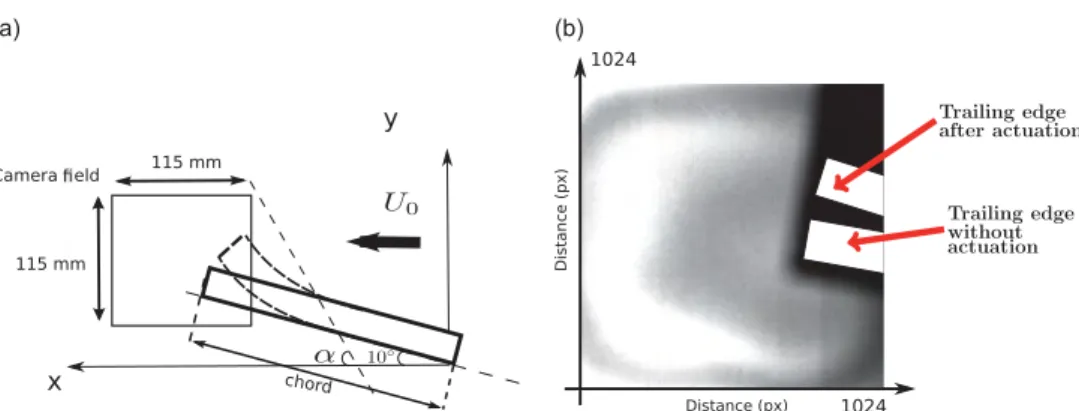
The size of the measurement plane was 115 " 115 mm2(seeFig. 2).Fig. 1a shows the experimental setup. A high-speed
camera (Photron-Fastcam RS3000) has been used to capture the particle displacements in the flow-field at the end of the trailing edge of the plate. The camera is equipped with a 105 mm Nikon lens. The depth of field was focussed on the laser light sheet which corresponds to the x–y plane. The laser pulsations were generated by a two-cavity ‘Nd:YLF’ (527 nm) laser (Quantronix, Darwin Duo).Fig. 1b shows the optical path of the laser beam. The laser sheet is created and focussed using two lenses: L1 is a semi-cylindrical lens which creates the laser sheet while L2 focuses the laser sheet on the investigation area and ensures a homogenous width of the laser sheet after it has been reflected by a 451 inclined mirror. The position of the inclined mirror is fixed so that the laser sheet impacts in the middle of the structure. An additional mirror is positioned on top of the wind-tunnel in order to amplify the light intensity in the x–y plane. The thickness of the laser sheet is Δx ! 2:5 mm.
It is assumed that the plate is uniformly deformed (bent) along the y-axis with no torsional deformation. The position of the plate's trailing edge is tracked by the impact of the laser sheet on the top and bottom of the trailing edge. An optical high-pass filter is positioned on the wind tunnel window in order to reduce the amplitude of the specular laser reflections by the structure. The size of the interrogation window is 16 " 16 px2(px being Pixel) which corresponds to 1.79 " 1.79 mm2.
The recording frequency of the camera is 2 kfps (kilo frames per second). The laser pulse frequency is fixed at 1 kHz while the delay between the two laser pulses is 83 μs. Therefore, the sampling rate is 1 kHz for theTRPIVmeasurements.
3. Plate actuation by shape memory alloys 3.1. Shape memory alloys
SMAs are defined by a thermo-mechanical coupling. Actuators based onSMAtechnologies generally modify the shape of a
structure by changing the temperature of the material (Lan and Fan, 2010). This kind of material is generally composed of a metallic alloy. In this paper the chosen material is Nickel and Titanium (NI–TI) which is an alloy ofNI–TI. This kind ofSMAis
well described in the literature (Ro and Baz, 1995;Baz et al., 2000).
The shape modification of SMAs is due to a change in the crystalline phase induced by a variation of the material's
temperature. One can distinguish between two different crystalline phases. The first one observed at low temperature is called the Martensitic phase (Duerig and Pelton, 1994). The second phase, called Austenite, is obtained after heating. The macroscopic deformations are due to the break of the high symmetry level in the initial crystalline phase. The phase change is defined as a reversible non-instantaneous process.SMAs are characterized by a variety of properties such as super-elasticity
during the phase change and the shape memory effect. However, one of the most important properties of SMAs is the
hysteresis effect between the Martensite–Austenite transformation.Fig. 3a shows the typical hysteresis curve observed for
SMAs for different current intensities. The displacement of a spring connected to aNI–TIwire (∅1 mm) is plotted against the
temperature of the wire.
Amongst all the mechanical properties ofSMAs this work focuses on the shape memory effect as a means for actuation
and deformation. By exploiting this material property the maximum deformation of aNI–TIwire is ! 10% at constant strain.
However for actuation purposes, the aforementioned hysteresis phenomenon has to be taken into account in order to precisely control the displacement. A suitable control parameter is yet to be identified (Brammajyosula et al., 2011).
Fig. 3b illustrates the maximum temperature increasing with the current intensity. Additionally, one can observe that the temporal dynamics are largely improved with increasing current intensity. Therefore, in order to quickly reach a certain displacement and maintain this position a combination of a high current pulse with a constant low intensity current is the most advisable way to proceed.
3.2. Actuated plate
The plate actuated usingSMAs is made of polyether ether ketone (PEEK) with the dimensions of 15 " 320 " 585 mm.
TheSMAwires are embedded in the surface of the plate as shown inFig. 4(Chinaud et al., 2012). In this configuration, the displacement of the SMAs allows a maximum bending displacement of the trailing edge of ! 36 mm. The maximum
displacement at 16.9 A is obtained in 1 s, which is an important parameter to take into account concerning the velocity measurement in the wind tunnel during the dynamic regime. The placement of theSMAwires on both sides of the plate allows a twisting and a bending movement both in the positive and in the negative direction of the y-axis. In the present study only the bending deformation has been considered.
This experimental work is divided into two parts: a static study for which the plate is deformed by injecting a constant current corresponding to a given radius of curvature and a dynamic study during which the deformation process is progressively performed up to the maximum bending.
The theoretically calculated shape of the prototype for different current intensities is shown inFig. 5a. The shapes were calculated under the assumption that the Euler–Bernoulli beam theory holds. Image analysis allowed the comparison of the different trailing edge positions obtained by the theoretical model with those obtained experimentally. This process gives us the position of trailing for different current intensities. The experiments confirmed the theoretically calculated deformation.
Fig. 2. (a) Sketch of the camera field at the trailing edge of the structure. (b) Recorded image with the trailing edge of the flat plate with and without actuation.
Fig. 3. (a) Temperature of aSMAwire (∅ ¼ 1 mm) vs. the displacement. (b) Surface temperature of aSMAwire for different electrical currents.
For a 36 mm deflection, which corresponds to ! 10% of the chord, the radius of curvature is decreasing from 1000 cm to 100 cm. The trailing edge position for different currents can be seen inTable 1.
The same method cannot be applied in the dynamic case because the theoretical modelling is much more complicated due to the crystalline transformation.Fig. 5b shows the evolution the trailing edge position for a current intensity of 16.9 A, obtained by image analysis. After an intensity decrease at t ! 1:7 s the trailing edge begins to descend.
4. Results
The results are organised as follows: first, the static case at 101 of incidence is analyzed using time-averaged velocities, Reynolds stresses and dynamics of the near-wake structure, especially in the separated shear layer. Second, the deformed static cases corresponding to the current intensities 2.75 A, 3.5 A and 4 A are discussed and compared with the dynamic case, whose results are phase-averaged at the same positions of the deformed plate as for those of the static case. These positions of the trailing edge are defined from the coordinates of the lower edge of the plate as indicated inFig. 5b and
Table 1.
4.1. Time-averaged velocity components and velocity magnitude for the static case
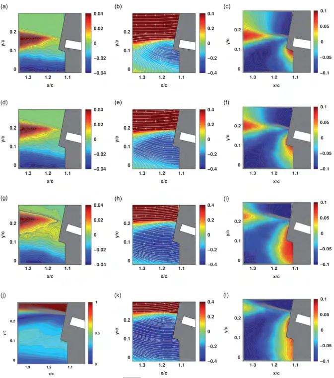
The time-averaged velocity field measurements can be seen inFig. 6for the flat plate at different radii of curvature corresponding to the current intensities of 0 A, 2.75 A, 3.5 A and 4.0 A. Three-thousand consecutive fields were averaged for each case, and the results have been normalized by the freestream velocity U1. The time-averaged fields are calculated by
having checked the stationarity of the statistical process with 1000, 2000 and 3000 snapshots.
The flow dynamics past the flat plate are mainly organized around two coherent processes as discussed in this section: the shear-layer development past the trailing edge and the von-Kármán vortices below it.Fig. 6shows the time-averaged iso-contours of the velocity magnitude and of the longitudinal (U) and vertical (V) velocity components normalized by the upstream velocity. The formation of a massive separation area below the flat plate can be seen in the first two columns of this figure. The averaged shear-layer region past the trailing edge is more clearly illustrated in the third column of this figure (time-averaged vertical velocity component).
By comparingFig. 6a and d it can easily be seen that even a slight increase in the radius of curvature (seeFig. 5a for the trailing-edge position) leads to a significant increase in the recirculation area below the plate. In the case of no actuation the time-averaged flow recovers fairly quickly after the separation area. Evidently this recovery takes longer, spatially speaking, as the radius of curvature of the plate rises with increasing current intensity (compareFig. 6a–j). A larger dimension of the measuring plane would be necessary for capturing the whole recirculation area as a function of increasing of the current's intensity. However, as will discussed in one of the next sections, the presentTRPIVmeasurements aim at the shear layer
dynamics modification as a function of the variation of the plate's position. Therefore, a compromise was needed, in order to
Fig. 5. (a) Theoretical neutral fibre in the quasi-static case given for different current intensities. (b) Dynamics of the trailing edge for 16.9 A. Positions ‘1’, ‘2’ and ‘3’ are indicated by dotted lines.
Table 1
Position of the trailing edge for the different studied points in the static case.
Location x/c y/c Current intensity (A)
Position 0 0.980 0.173 0.00 Position 1 0.983 0.199 2.75 Position 2 0.987 0.225 3.50 Position 3 0.993 0.251 4.00 Position 4 0.998 0.277 4.80
ensure a high image resolution within a reduced measurement plane, instead of enlarging the size of the measurement plane.
With respect to the normalized iso-longitudinal velocity component U =U1and to the vertical velocity component V =U1
it can be seen that the increase in the radius of curvature of the plate from 0.00 A to 4.00 A displaces the region of maximum shear farther downstream of the trailing-edge and provides a stronger curvature in the shear-layer region that develops in increasingly upper positions. When the actuation reaches 4 A, a maximum shearing structure is obtained behind the trailing edge.
Fig. 6c–l shows the V =V1velocity contours for the different deformation positions. A two-lobe structure is systematically
formed: the first downstream of the trailing-edge and the second directly below the trailing edge. Whereas the first lobe (g)
Fig. 6. Time-averaged velocity magnitude, M =U1¼ ð
ffiffiffiffiffiffiffiffiffiffiffiffiffiffiffiffiffi U2þ V2
q
Þ=U1 and velocity components, U =U1 and V =U1 for different static positions.
(a) M I ¼ 0 A. (b) U I ¼ 0 A. (c) V I ¼ 0 A. (d) MI ¼ 2:75 A. (e) U I ¼ 2:75 A. (f) V I ¼ 2:75 A. (g) MI ¼ 3:50 A. (h) U I ¼ 3:5 A. (i) V I ¼ 3:5 A. (j) M I ¼ 4:00 A. (k) U I ¼ 4:0 A. (l) V I ¼ 4:0 A.
downstream of the plate is shifted even farther downstream as a function of the curvature increases, the second lobe below the trailing edge of the plate grows in size.
4.2. Reynolds stresses for the static case
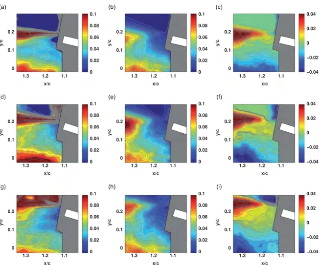
Fig. 7a, d, g and j shows the time-averaged normalized Reynolds stress fields. The maximum u2stress occurs in the shear
layer, as well as in the lower recirculation area. As the actuation increases towards the higher bending positions, it can be seen that the maximum u2 region has been widely spread downstream in the shear layer and simultaneously, the lower
recirculation area has increased. The Reynolds stress v2=U2
1 shows two maximum areas within the von-Kármán vortex
region at position ‘0’ (i.e. without actuation). The maximum v2stress occurs in the recirculation area below the shear layer.
The increase in current intensity and hence the decreasing radius of curvature of the plate sweeps the maximum v2region
Fig. 7. Comparison of normalized u2=U2 1, v2=U
2
1and uv=U 2
1for different static positions. (a) u2I ¼ 0 A. (b) v2I ¼ 0 A. (c) uvI ¼ 0 A. (d) u2I ¼ 2:75 A.
farther downstream as can be seen by comparingFig. 7e, h and k withFig. 7a. By comparing the space variations of the normal stress components (first two columns) of this figure, it can be seen that the maximum gradients between the longitudinal and the vertical Reynolds stress are located in different space positions. This indicates an anisotropic character of the turbulence process in the present formation region of the main instabilities governing the near-wake and the trailing edge dynamics.
The shear stress component uv=U2
1shown inFig. 7c, f, i and l displays high gradients similar to a two-lobe structure that
generally characterizes the turbulent wakes (Perrin et al., 2007). The maximum gradients are more concentrated around the shear layer, as the actuation intensity increases.
4.3. Time-averaged velocity magnitude, velocity components and Reynolds stresses for the dynamic case
Figs. 8and9show the normalized iso-contours of the longitudinal velocity component and of the Reynolds stresses, respectively, for the dynamic cases. The comparison of the static and dynamic cases are performed as follows: phase-averaged fields (designated by the symbol 〈 〉) have been provided for the dynamic positions corresponding to the static positions described in the previous section. The phase-averaged velocity fields and Reynolds stresses can be compared to their corresponding counterparts (i.e.Fig. 8compared withFig. 6andFig. 9compared withFig. 7).
It can be seen that these fields compare qualitatively quite well. However, the following differences are depicted concerning the dynamic case: the recirculation area is formed at a lower position than in the static case, as can be seen in the phase-averaged longitudinal velocity iso-contours. The 〈V 〉 velocity shearing regions are less pronounced in the dynamic case and the maximum velocity gradients in the mixing layers and in the lower area are less expanded. Moreover, the longitudinal phase-averaged normal stress displays a progressively different topology in the mixing layer for the higher positions than in the static case. The maximum gradients of the vertical phase-averaged Reynolds stress become progressively more pronounced for the higher positions than in the static case. The phase-averaged shear-stress maximum gradients in the mixing layer region are stronger in the dynamic case. In all cases, the lower region displays significant differences. This needs a new set of measurements in a future study, by using two measurement's planes of equal size,
Fig. 8. Comparison of time-averaged, normalized 〈M 〉=U1¼ ð
ffiffiffiffiffiffiffiffiffiffiffiffiffiffiffiffiffiffiffiffiffiffiffiffi 〈U2〉þ 〈V2〉
q
Þ=U1, 〈U 〉=U1and 〈V 〉=U1for the dynamic positions corresponding to positions
located downstream of the present one and below it, respectively, in order to better capture these differences between the static and dynamic cases. These differences can be attributed to the additional kinetic energy provided by the dynamic actuation and to the memory effects during the motion. Therefore, by means of the present analysis, it can be seen that the well-known ‘quasi-static’ hypothesis, widely used in aeroelasticity of low-frequency wing motion and often applied under ideal fluid-flow assumptions, has to be carefully considered in the design. Indeed, the viscous effects in the near-region, associated with the turbulence quantities presented, may create a deviation from the quasi-static hypothesis. This has to be taken into account in the present Reynolds number range corresponding to the low-subsonic speed phases of the motion, governed by strong flow detachments and instabilities, phenomena that are much more pronounced than in transonic (cruise) speeds. Especially, the modification of the shear-layer instability and of the von-Kármán mode under the actuation effect will be analysed in the next section.
4.4. Shear-layer dynamics past the trailing edge
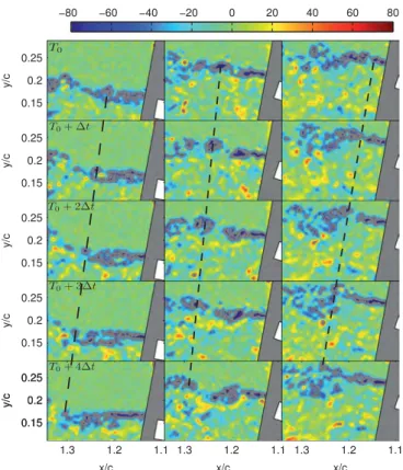
Fig. 10 shows the time-dependent evolution of the shear-layer downstream of the trailing edge, by means of the instantaneous vorticity fields. Three groups of figures are discussed, position ‘0’ without actuation, and positions ‘2’ and ‘3’ of the actuated plate. For all cases, a shear layer is clearly formed downstream of the trailing edge. A series of Kelvin– Helmholtz (K–H) vortices can be clearly identified. By performing a space–time tracking of these vortices, thanks to theTRPIV
measured iso-vorticity fields, the dimensionless wavelength λx=c of these vortices has been found to be of order 0.04. By
combining the space–time evolutions and fast Fourier transform (FFT) of the vertical velocity signals, the shedding frequency
of the shear-layer vortices has been assessed to be of the order of 300 Hz. It is well known that the K–H vortices and their frequency are responsible for acoustic noise downstream of a thin body (plate, aileron, etc.).
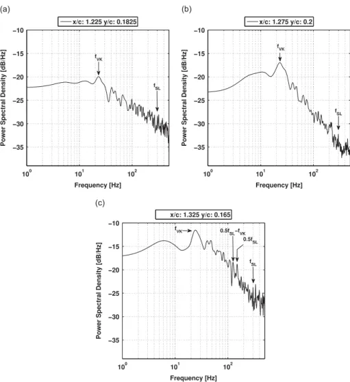
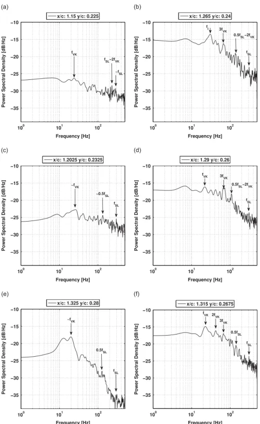
The area below the shear layer is mainly governed by the von-Kármán vortex dynamics, as can be seen in the power spectral densities in Figs. 12and 13. At the present high Reynolds number range, the von-Kármán vortices include a
Fig. 9. Comparison of 〈u2〉=U2 1, 〈v2〉=U
2
1and 〈uv〉=U 2
1for for the dynamic positions corresponding to phases 1, 2, 3 ofTable 1for the plate's motion.
multitude of small-scale vortices characterized by higher frequencies in the energy spectrum. The shear-layer is found to interact strongly with the von-Kármán area, in which it is entrained, as shown for position ‘3’, T0þ 2Δt to T0þ 4Δt. This
phenomenon occurs for all of the plate's positions investigated. The interaction with the von-Kármán area delays the shear-layer and creates vortex pairings, as for example in the case of position ‘0’, T0( T0þ 2Δt, and position‘2’ ,T0. This vortex
pairing makes appearance of the first subharmonic of the shear-layer frequency in the energy spectra, as shown inFig. 13. This phenomenon appears for all deformed plate positions and creates K–H vortices merging.
Fig. 12shows the spectral density of the vertical velocity component at different monitoring points. The location of each probe (monitoring point) with respect to the trailing edge of the plate can be seen inFig. 11.
The region below the shear layer is characterized by the von-Kármán vortex shedding, as can be seen in the power spectral density (PSD). The von-Kármán vortices are composed of smaller-scale structures because of the high Reynolds
number of the flow. The von-Kármán frequency is of 22 Hz. In the article byDeri et al. (this issue), performing Tomo PIV around the static flat plate configuration, the measurements domain is located farther downstream and captures the configuration of the von-Kármán vortices. In the present study, the choice of the measuring plane allows tracking the shear-layer and its interaction with the von-Kármán area.
Fig. 10shows the entrainment of the shear-layer vortices within the von-Kármán area. This interaction is characterized by the appearance of frequency peaks in the spectrum that are combinations of the von-Kármán frequency and of the shear-layer frequency. The formation of vortex pairings in the shear layer increases the subharmonic frequency fSL=2, as shown in the spectra. In the cases of higher incidence and plate deformations, the shear layer is displaced in an upper region and the von-Kármán area is characterised by a higher spectral intensity of the von-von-Kármán mode. Consequently, the interactions between this mode and the shear-layer mode are more pronounced than in position ‘0’, as shown in the spectra,Fig. 13(left) concerning the frequency peaks fIin the lower frequency range. It is known that the energy spectrum governed by two main
instability modes of two incommensurate frequencies creates non-linear interactions that produce predominant frequency peaks which are linear combinations of these two frequencies. This fact clearly appears in the present energy spectra, where a number of these interactions have been identified. The actuation corresponding to ‘position 3’ produces a lower spectral energy level (in absolute value) than the actuation of ‘position 4’.
5. Conclusion
The work carried out provided a detailed study of the near-wake turbulent structure modification of a deformed plate constructed of PEEK, according to actuation achieved bySMAofNI–TI. The deformation achieved has been of order 10% of the
Fig. 10. Time-dependent evolution of the shear layer vortices (Δt ¼ 0:001) corresponding to successiveTRPIVvorticity fields (evolution from top to bottom): position ‘0’ (left), position ‘2’ (middle) and position ‘3’ (right). For the positions refer toTable 1.
chord at a low operating frequency of the order of 1 Hz. The instrumentation of the plate of dimension (32 " 58.5 " 1.5) cm2
was successfully achieved usingSMAs in the wind tunnel, by supporting the aerodynamic loads in the Reynolds number
range of 200 000 corresponding to the low range of subsonic flight of a trailing-edge aileron.
The present study has shown the ability of the present SMA actuators to achieve bending of the trailing-edge of a
plate while supporting the loads from a fluid at the present Reynolds number. Therefore, an efficient demonstration of
Fig. 11. Location of the monitoring points generating thePSDs.
electroactive morphing has been achieved in a laboratory environment, allowing us to study the impact of the shape modification on the vortex structures and instabilities past the trailing-edge. In this paper, by efficiently controlling the temperature of theSMAs, control of the stiffness and control of the curvature of the plate have been achieved, in order to
modify the vortex structure of the shear-layer instability past the trailing edge.
The effects of the present electro-active morphing have been studied in detail by means ofTRPIVmeasurements in wind
tunnel experiments for the present Reynolds number range. As a first step, this study quantified in detail the vortex structure in the very near-region past the trailing-edge without actuation, at 101 incidence. This region is found to be governed by the von-Kármán instability, responsible for large separation, by the shear-layer instability, associated with the formation of Kelvin–Helmholtz vortices downstream of the trailing edge and by smaller-scale vortices corresponding to the random turbulence. The topology of the statistically averaged flow quantities (mean velocities and Reynolds stresses) has been quantified in this near-region. The mean velocities clearly illustrate the separation effect due to the von-Kármán mode. The normal Reynolds stresses display their maximum values in the shear layer and within the main recirculation areas and confirm the highly anisotropic character of the turbulent motion (non-equilibrium turbulence), by the fact that the maximum locations of the normal stresses do not occur at the same positions. The shear stress fields indicate maximum values in the mixing layer. Second, intermediate static cases have been studied and compared with the dynamic case of the plate's continuous deformation, by performing phase-averaging at the same intermediate static positions. It has been found that the increase of curvature by increasing the current intensity produces a larger recirculation area and an increase of the Reynolds stress gradients. The dynamic actuation produces an increase of shear in the mixing-layer area past the trailing-edge and a considerable change in the topology of the shear layer. The comparison between the dynamic case and selected intermediate static cases shows a qualitative similarity. Nevertheless, quantitative differences have been depicted in the high shear-layer regions, due to the viscous effect and the associated turbulence motion. Therefore, the ‘quasi-static’ hypothesis, often adopted especially in the case of higher Reynolds numbers corresponding to cruise speeds, has to be carefully reconsidered in the present Reynolds number range, corresponding to the low-subsonic aileron's flight phase. Furthermore, the present study provided the detailed structure of the shear-layer dynamics, of the wavelength and of the predominant frequency governing the K–H vortices. The study of the energy spectra for the different actuation positions shows that the increase of the incidence and decrease of the radius of curvature of the plate lead to a stronger interaction of the von-Kármán mode within the shear-layer frequency of the Kelvin–Helmholtz vortices by means of selected actuations, a reduction of the spectral energy and a reduction of the frequency peaks governing the mixing layer have been achieved. This has the potential to significantly reduce the trailing-edge aerodynamic noise during take-off and landing.
Acknowledgments
The present work has been sponsored by the French FoundationSTAEby the research program emmav in the context of
the Smartwing Morphing Center (SMC), www.smartwing.org. The authors are grateful to M. Christophe Korbuly for his
technical aid concerning theTRPIVexperiments in the S4 wind tunnel ofIMFT.
References
Barbarino, S., Dettmer, W.G., Friswell, M.I., 2010. Morphing trailing edges with shape memory alloy rods. In: Proceedings of the 21st International Conference on Adaptive Structures and Technologies (ICAST), vol. 4.
Barbarino, S., Pecora, R., Lecce, L., Concilio, A., Ameduri, S., Calvi, E., 2009. A novelSMA-based concept for airfoil structural morphing. Journal of Materials Engineering and Performance 18 (5), 696–705.
Baz, A., Chen, T., Ro, J., 2000. Shape control of NITINOL-reinforced composite beams. Composites Part B: Engineering 31 (8), 631–642.
Brailovski, V., Terriault, P., Georges, T., Coutu, D., 2010.SMAactuators for morphing wings. Physics Procedia 10, 197–203.
Brammajyosula, R., Buravalla, V., Khandelwal, A., 2011. Model for resistance evolution in shape memory alloys including R-phase. Smart Materials and Structures 20 (3), 035015.
Cadogan, D., Smith, T., Lee, R., Scarborough, S., Graziosi, D., April 2003. Inflatable and rigidizable wing components for unmanned aerial vehicles. In: The 44th AIAA/ASME/ASCE/AHS/ASC Structures, Structural Dynamics, and Materials Conference. Structures, Structural Dynamics, and Materials and Co-located Conferences. American Institute of Aeronautics and Astronautics. URL: 〈http://dx.doi.org/10.2514/6.2003-1801〉.
Chinaud, M., Boussaid, A., Rouchon, J., Duhayon, E., Deri, E., Harribey, D., Braza, M., 2012. Thermo-mechanical coupling in Nitinol. Application to an electro-morphing plate. In: 2012 XXth International Conference on Electrical Machines (ICEM). IEEE, pp. 2580–2584.
Chinaud, M., Scheller, J., Rouchon, J.F., Duhayon, E., Braza, M., 2013. Hybrid electroactive wings morphing for aeronautic applications. Solid State Phenomena 198, 200–205.
Commission, E., November 2012a. Fp7-Aeronautics and Air Transport (aat)-2013-rtd-1. URL: 〈http://ec.europa.eu/research/participants/portal/page/ call_FP7?callIdentifier=FP7-AAT-2013-RTD-1&specificProgram=COOPERATION#wlp_call_FP7〉.
Commission, E., November 2012b. Fp7-Aeronautics and Air Transport (aat)-2013-rtd-1. URL: 〈http://ec.europa.eu/transport/themes/research/horizo n2020_en.htm〉.
Deri, E., Braza, M., Cid, E., Cazin, S., Michaelis, D., Degouet, C., Investigation of the three-dimensional turbulent near-wake structure past a flat plate by tomographic {PIV} at high Reynolds number. Journal of Fluids and Structures, this issue. URL: 〈http://www.sciencedirect.com/science/article/ pii/S0889974612002095〉.
Duerig, T., Pelton, A., 1994. TiNi shape memory alloys. In: Boyer, R.F., Collings, E. (Eds.), Materials Properties Handbook: Titanium Alloys, ASM International, pp. 1035–1048.
Faria, C.T., De Marqui Jr. C., Inman, D.J., Lopes Jr., V., 2012. Nonlinear dynamic model and simulation of morphing wing profile actuated by shape memory alloys. In: Topics in Nonlinear Dynamics, vol. 3. Springer, pp. 21–28.
Hall, S.R., Prechtl, E.F., 1999. Preliminary testing of a Mach-scaled active rotor blade with a trailing-edge servo flap. In: 1999 Symposium on Smart Structures and Materials. International Society for Optics and Photonics, pp. 14–21.
Hartl, D., Lagoudas, D.C., 2007. Aerospace applications of shape memory alloys. Proceedings of the Institution of Mechanical Engineers Part G: Journal of Aerospace Engineering 221 (4), 535–552.
Huang, W., Ding, Z., Wang, C., Wei, J., Zhao, Y., Purnawali, H., 2010. Shape memory materials. Materials Today 13 (7–8), 54–61. URL: 〈http://www. sciencedirect.com/science/article/pii/S1369702110701280〉.
Jänker, P., Hermle, F., Friedl, S., Lentner, K., Enenkl, B., Müller, C., 2006. Advanced piezoelectric servo flap system for rotor active control. In: 32nd European Rotorcraft Forum, Maastricht, The Netherlands.
Kakubari, Y., Sato, F., Matsuki, H., Sato, T., Luo, Y., Takagi, T., Yambe, T., Nitta, S., 2003. Temperature control ofSMAartificial anal sphincter. In: Magnetics
Conference, 2003 (INTERMAG 2003). IEEE International. IEEE, pp. FR-05.
Lagoudas, D.C., 2008. Shape Memory Alloys: Modeling and Engineering Applications. Springer.
Lan, C.-C., Fan, C.-H., 2010. An accurate self-sensing method for the control of shape memory alloy actuated flexures. Sensors and Actuators A: Physical 163 (1), 323–332.
Manzo, J.E., 2006. Analysis and Design of a Hyper-Elliptical Cambered Span Morphing Aircraft Wing (Ph.D. thesis), Cornell University.
McGowan, A.-M.R., Wilkie, W.K., Moses, R.W., Lake, R.C., Florance, J.P., Wieseman, C.D., Reaves, M.C., Taleghani, B.K., Mirick, P.H., Wilbur, M.L., 1998. Aeroservoelastic and structural dynamics research on smart structures conducted at NASA Langley Research Center. In: The Fifth SPIE International Symposium on Smart Structures and Materials, San Diego, CA.
Perrin, R., Braza, M., Cid, E., Cazin, S., Barthet, A., Sevrain, A., Mockett, C., Thiele, F., 2007. Obtaining phase averaged turbulence properties in the near wake of a circular cylinder at high Reynolds number using POD. Experiments in Fluids 43 (2–3), 341–355.
Ro, J., Baz, A., 1995. Nitinol-reinforced plates: part I. Thermal characteristics. Composites Engineering 5 (1), 61–75.
Senthilkumar, P., Jayasankar, S., Sateesh, V., Kamaleshaiah, M., Dayananda, G., et al., 2013. Development and wind tunnel evaluation of a shape memory alloy based trim tab actuator for a civil aircraft. Smart Materials and Structures 22 (9), 095025.
Song, G., Ma, N., 2007. Robust control of a shape memory alloy wire actuated flap. Smart materials and Structures 16 (6), N51.
Straub, F.K., Kennedy, D.K., Stemple, A.D., Anand, V., Birchette, T.S., 2004. Development and Whirl Tower Test of the SMART Active Flap Rotor, San Diego, CA, USA, March.
Strelec, J.K., Lagoudas, D.C., Khan, M.A., Yen, J., 2003. Design and implementation of a shape memory alloy actuated reconfigurable airfoil. Journal of Intelligent Material Systems and Structures 14 (4–5), 257–273.
Sutou, Y., Imano, Y., Koeda, N., Omori, T., Kainuma, R., Ishida, K., Oikawa, K., 2004. Magnetic and martensitic transformations of NiMnX (X ¼ In, Sn, Sb) ferromagnetic shape memory alloys. Applied Physics Letters 85, 4358.
Thill, C., Etches, J., Bond, I., Potter, K., Weaver, P., 2008. Morphing skins. Aeronautical Journal 112 (1129), 117–139.
Ursache, N., Melin, T., Isikveren, A., Friswell, M., September 2007. Morphing winglets for aircraft multi-phase improvement. In: 7th AIAA ATIO Conference, 2nd CEIAT International Conference on Innovation and Integration in Aero Sciences, 17th LTA Systems Technology Conference; followed by 2nd TEOS Forum. Aviation Technology, Integration, and Operations (ATIO) Conferences. American Institute of Aeronautics and Astronautics. URL: 〈http://dx.doi. org/10.2514/6.2007-7813〉.
Valasek, J., 2012. Morphing Aerospace Vehicles and Structures, vol. 56. John Wiley & Sons.