Science Arts & Métiers (SAM)
is an open access repository that collects the work of Arts et Métiers Institute of
Technology researchers and makes it freely available over the web where possible.
This is an author-deposited version published in: https://sam.ensam.eu Handle ID: .http://hdl.handle.net/10985/7155
To cite this version :
Mehdi IRAQI-HOUSSAINI, Mathias KLEINER, Lionel ROUCOULES - Tools interoperability in engineering design using Model-Based Engineering - In: Engineering Systems Design and Analysis ESDA2012, France, 2012-07 - Proceedings of the 11th Biennial Conference on Engineering Systems Design and Analysis - 2012
Proceedings of the 11th Biennial Conference on Engineering Systems Design and Analysis ESDA2012 July 2 - 4, 2012, Nantes, FRANCE
ESDA2012-82290
TOOLS INTEROPERABILITY IN ENGINEERING DESIGN USING MODEL-BASED
ENGINEERING
IRAQI HOUSSAINI Mehdi Arts et métiers ParisTech,
CNRS, LSIS
2, cours des Arts et Métiers, 13617 Aix-en-Provence, France
Email : [email protected]
KLEINER Mathias Arts et métiers ParisTech,
CNRS, LSIS
2, cours des Arts et Métiers, 13617 Aix-en-Provence, France
Email :
ROUCOULES Lionel Arts et métiers ParisTech,
CNRS, LSIS
2, cours des Arts et Métiers, 13617 Aix-en-Provence, France
Email :
ABSTRACT
Computer-aided engineering is widely used in various areas including manufacturing, requirement planning and product design. These specific CAE tools, here called expert tools, manipulate large amounts of data. Some of those data also need to be processed by other expert tools to allow a flexible collaboration between various experts. This article proposes an approach to exchange data of various formats manipulated by different expert tools through model-based technologies. The presented approach is validated by its implementation on an academic use case involving commercial industrial tools.
INTRODUCTION
Computer-aided engineering (CAE) is the broad usage of computer software to aid in engineering tasks. These expert tools are increasingly specialized given the growing complexity of the various systems to design (system size, multi-domains, etc.) and have major interoperability issues. Thus, Industrial activities generate and manipulate large amounts of data of various formats that need to be stored and exchanged consistently so as to ease collaboration (i.e. interoperability [18]) between experts using different tools.
Model Driven Architecture (MDA) [2, 24] reflects the OMG’s approach to using models in software development to deploy, maintain and integrate applications with far less cost and time than traditional approaches. The primary goals of MDA are portability, interoperability, and reusability through
architectural separation of concerns [2]. More recently, there has been an effort to investigate the applicability of OMG MDA to the discipline of systems engineering specifically model-based systems engineering (MBE) [3, 23]. MDA could provide the types of productivity gains in systems engineering on par with the productivity gains that have been demonstrated in the software engineering community. By definition MBE includes MDA.
The presented work takes place in a federative approach to this interoperability problem using model-based engineering techniques: various expert tools, based on the design process, should be combined and linked in a dynamic and flexible way by modeling the semantic and syntactic relations between them in a tool independent environment [3].
This article tackles one of the major issues for the application of model-based engineering to the context of product design: the ability to exchange data manipulated by any expert tool with the MBE environment. We propose an approach to handle this operation depending on the formats in which the expert data is available.
This paper is organized as follows: The context and related work section introduces briefly the context of computer-aided engineering for product design and MBE main principles. Expert data projection section presents the proposed approach to exchange data manipulated by any expert tool using the MBE environment. Our work is backed by its implementation on an
academic use case explained in the usecase section. Conclusion and future work section concludes this article and proposes directions for future research.
CONTEXT AND RELATED WORK Introduction To CAE And Product Design
The current competitive market demands a quality product both in terms of reliability and durability. Product design aims at creating a product and following its development through its entire lifecycle. The design process main objective is to define (or develop) a product that satisfies a need.
However, product design is getting more and more complex. It has to ensure traceability all along the design process and answer different issues and needs through complex functions following several phases: requirement specification, conceptual design, manufacturing, exploitation, etc.
CAE is widely used to improve product design and to resolve engineering issues for a wide range of areas and disciplines. This includes functional analysis, CAD model, structural analysis, manufacturing simulation…. Authors refer to these tools as expert tools in this article. These expert tools offer benefits including reduced product development cost and time.
Interoperability [18] is the ability of two or more systems to communicate, cooperate and exchange data and services, despite of the differences in languages and implementations. Interoperability between expert tools can be defined following three distinct points of view [19]:
- Integration: all product models use the same standard or a shared representation as a hub to formalize these models. The representation is either non-standardized, or specific to a given business [25].
- Unification: one common data structure offers the possibility to establish semantic correspondences between different product models [17].
- Federation: several distinct product models are dynamically linked based on a correspondence map, based on several concepts which are related at the semantic level (relationships of similarity or equivalence) [3].
Some limits of the CAE expert tools that will be discussed in that paper have been identified:
- Authors assume that a unique software that cover every functions to assess all the product’s behaviors on its entire lifecycle do not exist
- Some solutions cover a large scope of those functions that easily supports the semantic interoperability (i.e. integrated approach) but therefore do not provided very accurate functions
- On the contrary, some solutions cover very specific functions but therefore less interoperable (i.e. federative approach)
- PLM solutions are mainly based on data (or files) management but do not really tackle the semantic interoperability.
Introduction To Model-Based Engineering
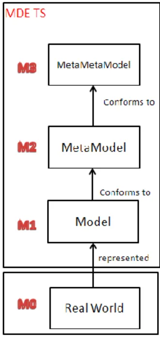
Model-based engineering (MBE) is a methodology that provides tools, concepts and languages to create and process models. The main principles of the MBE four-level architecture are represented in Figure 1.
A model is a view or a representation of a system that captures some characteristics of that system and provides knowledge about it. MBE offers a large variety of tools (and languages) that enables us to create, process and exchange knowledge between different models expressed in precise metamodels. The syntactic rules used to express a model are called a metamodel. The latter is expressed in a unique self-descriptive meta-metamodel.
FIGURE 1. REPRESENTATION OF THE FOUR-LEVEL ARCHITECTURE OF MBE
To understand the concept of conformity shown in Figure 1, a model is conformed to a metamodel if and only if all elements of this model are defined by the metamodel.
MBE offers a number of advantages such as cost reduction throughout the product (software) life cycle, reduced development time for new products and platform independence by modeling specifications independently of technologies.
The main idea of MBE is to define a declarative architecture to focus on the studied concepts and the links between them independently of the tools used to create these concepts. An implementation of MBE can be found in Eclipse Modeling Framework (EMF). EMF [4, 5] is a modeling framework for building tools and data-processing based on models.
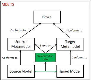
A model transformation [6, 7] is the generation of one or more target models from one or more source models according to a set of transformation rules. These rules describe how a model described in a source language can be transformed into a model described a target language. These models (target and source models) are described in one or more metamodels. The model transformation principles are represented in Figure 2.
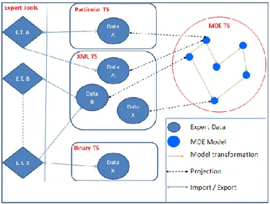
A technical space (TS) [1] is a set of techniques, principles, syntactic rules and tools associated to a particular format or domain (specific area). MBE provides an approach that integrates homogeneously various technical spaces through an operation to obtain models corresponding to these data and vice-versa. This operation is called data projection in latter sections. A general representation of the different levels of a particular TS (XML, ontologies, etc.) is represented in figure 3.
FIGURE 2. THE MODEL TRANSFORMATION PRINCIPLES
FIGURE 3. GENERAL REPRESENTATION OF A PARTICULAR TECHNICAL SPACE
Application Of MBE In Product Design
In this paper, authors have adopted a federative way to tackle interoperability issues as introduced in Context and related work section. The approach is based on the link between particular (i.e. expert tools) and MBE Technical space. The presented work takes place in a federative approach to this interoperability problem using model-based engineering (MBE) techniques.
MBE provides a solution to represent knowledge carried by different expert languages as models. Authors therefore consider that data created by an expert in particular TS and useful to other experts in another particular TS can be modeled and linked in an MBE environment (i.e. MBE TS).
Product design may then benefit from many advantages that an MBE approach can provide, such as:
- A management of relations between models that is independent of expert tools. This management is indeed achieved in the MBE TS and supports more easily the substitution from an expert tool to another and the flexibility related to modeling languages that will enrich the transformation among semantic models - The possibility to dynamically create the IT system
with respect to a specific design process.
A major challenge of this approach (treated in this paper) is to project data manipulated by an expert tool from its technical space to the MBE technical space and vice versa. This article aims to demonstrate the feasibility of these operations applied in the field of product design.
EXPERT DATA PROJECTION
Introduction
According to expert tools, it is possible to export and import data in several formats using proprietary textual or binary formats or standards (such as STEP [8, 9]). Subsequently, authors will consider separately two options:
- XML [10] (eXtensible Markup Language) a standard format for data exchanges.
- Other specific textual formats that conforms to a standard or a proprietary format.
In other cases (binary format) a solution to access expert data encoded in a binary format will be manually implemented and fall into one of the two options. A general representation of the architecture to project expert data to/from different technical spaces is explained in figure 4.
Authors propose in the following section a general approach to address these two options.
FIGURE 4. A GENERAL REPRESENTATION OF THE PROPOSED ARCHITECTURE TO PROJECT EXPERT DATA
XML Format
XML is a generic and extensible markup language. It allows to describe, organize, store and exchange data.
FIGURE 5. A GENERAL MECHANISM FOR PROJECTING AN XML FILE
The main features of XML are reflected in its name: - eXtensible: XML is extensible and can create specific
tags based on the processed data. - Markup: XML is a markup language.
- Language : XML is a meta-language (a language for writing other languages)
Figure 5 represents the proposed methodology to perform the operation of data projection from/to an XML file. A well-formed XML file is called valid when it conforms to an XSD file. An XSD (XML Schema Document) or (W3C XML Schema) is a standard used to describe in a structured way the content type, syntax and semantics of an XML document. One can also note that the XSD files are in fact XML documents.
The projection operation is based on a mapping between the XML schema and a corresponding metamodel. The later metamodel is automatically generated using the EMF framework from the XML schema.
Other Specific Textual Formats
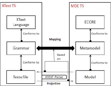
In this case, the manipulated expert data are accessible via a specific language or standard. It is usually possible to capture this syntax in a grammar. A grammar is a set of syntactic rules expressed in a particular formalism. Our proposed approach is based on grammar description language called XText [11, 12]. This approach is generalizable to other formalisms than XText.
FIGURE 6. USING XTEXT TO PERFORM DATA PROJECTION FROM/TO MBE TS
Figure 6 represents the proposed methodology to perform the operations of data projection using a specific grammar. XText is not used only to describe the grammar of a specific language, but can also generate the corresponding meta-model to a specific grammar, a parser and a text editor. In addition, you can declaratively define constraints on the grammar that will be checked into the editor.
USECASE
Introduction
In this section a case study is presented to apply both techniques to project expert data from industrial expert tools and the process of model transformation done to optimize and connect the metamodels.
This case study is supported by a design process that describes the different metamodels and expert tools involved in this case study as shown in figure 7. Relationships between these different metamodels are achieved through mapping operations [3]. These mappings are developed using the transformation language ATL [16, 7].
Authors illustrate the use of this case study on a simplified design scenario called delvion [13]. This scenario deals with the design of a system: the mechanical coupling between a plane propeller and a diesel engine. The design process aims at obtaining a description of an assembly of products from its functional analysis [3].
FIGURE 7. THE CONDUCTED CASE STUDY
We have chosen the Eclipse EMF platform as the implementation framework, mainly for its maturity and tools support. ECORE is used as the metametamodel language and ATL for model transformations.
The case study files, models and model transformations are open source and can be freely downloaded from a single package [22].
XML - TDC Software
TDC system [14] offers a large catalog of tools and collaborative platforms for system engineering and project management. TDC tools can export expert data in XML format. We are specifically interested in the functional analysis software TDC structure.
The TDC suite includes TDC Need, Structure, and FMEA, software which allows, respectively, External and Internal Functional Analysis, and running the FMECA (Failure Modes, Effects and Criticality Analysis) method. These three points of view complement each other and aim to improve design. During early stages of design, one must check that the product meets customer needs: these are translated into requirements by the designer, using TDC Need. The next step is searching for technical solutions and choosing the best one, using TDC Structure. Finally, the designer must verify the adequacy of the product to initial requirements, through TDC FMEA.
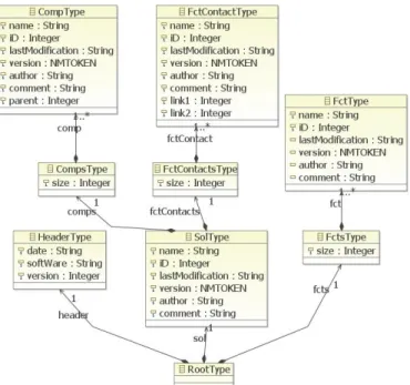
The first task was to define the XML schema corresponding to the TDC files exported using TDC structure because it was not directly available. Figure 8 shows an extract of the TDC metamodel corresponding to the TDC XSD. The later was generated using the EMF framework.
From the perspective of modeling XML schema is not as expressive as ECORE: XML schema may not specify the type of a reference target nor define bidirectional references [15].
FIGURE 8. EXTRACT FROM TDC METAMODEL It can be noted in figure 8 that the metamodel contains unnecessary intermediate concepts (for example –CompsType-). To obtain an optimized TDC metamodel (Figure 10) an ATL transformation is defined that runs as a result of the data projection as shown in figure 9.
ATL is a hybrid transformation language: it contains a mixture of declarative and imperative constructs. We encourage a declarative style of specifying transformations: It is usually based on specifying relations between a source and a target models and thus tends to be closer to the way the developers perceive a transformation [7]. We provide an extract of a transformation rule and a helper of the TDC metamodel to the optimized TDC metamodel ATL transformation in extract 1 [22].
FIGURE 9. THE GENERAL MECHANISM FOR PROJECTING TDC DATA
helper def: ensCompType: Sequence
(TDC!CompType)=TDC!CompType.allInstances() ; rule SolType{ from s5: TDC!SolType to st: TDCG!SolType( (…) name<-s5.name, iD<- s5.iD.toString(), comment<-s5.comment, author<-s5.author, comp<-Set{Sequence{ thisModule.ensCompType->collect(e| thisModule.resolveTemp(e,'ct'))}},
fctContact<-Set{Sequence{
thisModule.ensFctContactType->collect(e|thisModule.resolveTemp(e,'fct') )}},
tabCompFctType<-Set{Sequence{ thisModule.ensTabCompFctType->collect(e|thisModule.resolveTemp(e,'tcft' ))}}, (…) ) } rule CompType{ from s6: TDC!CompType to ct: TDCG!CompType( name<-s6.name, iD<-s6.iD.toString(), author<-s6.author, comment<-s6.comment, parent<-s6.parent.toString() (…) ) }
EXTRACT 1. EXTRACT OF THE TDC METAMODEL TO THE OPTIMIZED TDC METAMODEL ATL TRANSFORMATION
This style stresses on encoding these relations and hides the details related to selection of source elements, rule triggering and ordering, dealing with traceability, etc. Therefore, it can hide complex transformation algorithms behind a simple declarative syntax [7].
FIGURE 10. EXTRACT FROM THE OPTIMIZED TDC METAMODEL
STEP – CATIA Software
The STEP standard [8, 9] defines textual files which conform to a STEP schema (Application Protocol here AP-203), which in turn is defined using a relational language called EXPRESS [21]. The OMG had already considered the interoperability between STEP files and MBE models in the original XMI proposal.
Two alternatives were envisioned:
- A metametamodel mapping between EXPRESS and MOF, if any is possible due to the semantic gap. - A metamodel mapping between a specific STEP
schema and its counterpart metamodel.
We also underline an existing research activity that deals with STEP and EMF technical spaces [20]: A workbench which provides for the integration of the STEP and EMF technical spaces. This approach conforms to the first alternative envisioned by the OMG. To the best of our knowledge, the first alternative has been explored by various projects but is not yet mature. We chose the second alternative.
STEP provides a neutral medium to describe information about a product in most stages of its life cycle. STEP aims to enable communication between multiple expert tools. It covers many expert fields and is organized into a series of parts. Some of these parts are called Application Protocols (APs) that are used to describe expert data concerning a product for an application or a set of applications. In this case study the AP203 (design and configuration control) used in geometric modeling is particularly studied. The STEP format consists of two parts:
- The Header section contains, among other information, the reference to the data schema containing the description of the model in EXPRESS.
- The data section is presented as a series of instances of the classes described in the schema referenced in the header section.
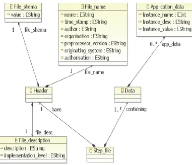
The proposed approach therefore established a STEP grammar using XText which contains all the rules for defining a STEP file. From this grammar the transformation automatically generates a STEP metamodel shown in figure 11. We provide an extract of the XText STEP grammar in extract 2 [22].
Step_file: "ISO-10303-21;" have=Header (containing+=Data(containing+=Data)* )? "END-ISO-10303-21;" ; Data : {Data} "DATA;" (app_data+=Application_data ( app_data+=Application_data)* )? "ENDSEC;" ; File_description : {File_description} "FILE_DESCRIPTION" "(("(description=EString)")," (implementation_level=EString)");" ;
EXTRACT 2. EXTRACT OF THE XTEXT STEP GRAMMAR Using this grammar defined via XText it is possible to project data found in the MBE TS into the STEP TS. However, since data is grouped into a single class called - Application_Data - (as shown in figure 11) it is difficult to manipulate the STEP models. Therefore authors created another metamodel to manipulate accurately data representing the description of a product, its arborescence and other information contained in the AP203. Figure 12 shows an excerpt of the AP203 metamodel.
FIGURE 11. METAMODEL OF STEP NEUTRAL FORMAT The solution that consists in using two metamodels was chosen to eventually manipulate data which conforms to other Aps than the AP203: All Aps meet the same structure of the neutral STEP format shown in figure 11.
Figure 13 represents the chain of transformation used for data acquisition (STEP-AP203) following an ATL transformation and a data projection to a STEP file.
FIGURE 12. EXTRACT FROM AP203 METAMODEL
FIGURE 13. THE GENERAL MECHANISM FOR PROJECTING STEP DATA
CONCLUSION AND FUTURE WORK
Authors defined a set of ATL model transformations to link the optimized TDC metamodel and the AP203 metamodel (open source and can be freely downloaded from a single package [22]). We thus can link the TDC to CATIA and obtain a description of a product assembly in CATIA from its functional and energetic analysis defined in TDC.
In this paper, authors proposed a general approach for acquiring and modeling expert data handled by different expert tools, using either language grammars or XML schemas. The presented work is validated by its implementation on an academic use case involving commercial industrial tools. Ongoing work is to extend the EXPRESS projection to other STEP schemas.
This work naturally follows previous work on adapting model techniques to the context of collaborative product design [3], by providing interoperability between different technical spaces. Future investigations will focus on one of the most promising parts of this federative approach: the ability to dynamically create and automate the (software) information system according to the product design process.
ACKNOWLEDGMENTS
This work has been partially funded by the French project ADN. The authors would also like to thank the TDC Team, for their help in understanding the concepts of the TDC suite in general and the TDC XML schema in particular.
REFERENCES
1. J. BEZIVIN, « Model Driven Engineering : An Emerging Technical Space », Lecture Notes in Computer Science, Volume 4143/2006, 2006 2. J.M. FAVRE, J. ESTUBLIER, M. BLAY,
« L'ingénierie dirigée par les modèles au-delà du MDA », Lavoisier, 2006
3. M. IRAQI-HOUSSAINI, M. KLEINER, L.
ROUCOULES, « Model-based (Mechanical) Product Design », Wellington, New Zealand, MODELS, 2011 4. EMF, Eclipse Modeling Framework,
http://www.eclipse.org/emf/
5. F. BUDINSKY, D. STEINBERG, E. MERKS, M. PATERNOSTRO, « Eclipse modeling framework: a developer’s guide », Series Editors: Erich Gamma - Lee Nackman – John Wiegand, 2008
6. K. CZARNECKI, S. HELSEN, « Feature-based survey of model transformation approaches » IBM Syst. J., 45:621, July 2006
7. F. JOUAULT, I. KURTEV, « Transforming Models with ATL », Proceedings of the Model Transformations in Practice Workshop at MODELS, Jamaica, 2005 8. ISO 10303:1994, Industrial automation systems and
integration – Product data representation and exchange is the formal name for the international standard familiarly known as STEP
9. ISO 10303-21:1994, Industrial automation systems and integration – Product data representation and exchange – Part 21: Implementation methods: Clear text encoding of the exchange structure
10. XML, http://www.omg.org/spec/XML/1.1/PDF 11. XText - a programming language framework,
http://www.eclipse.org/Xtext
12. S EFFTINGE, « oAW xText: A framework for textual DSLs », Eclipse Summit 2006, 22 Septembre 2006 13. Klein Meyer J.S. Modélisation multi-physique des
systèmes complexes dans un contexte de DFX. Application à la conception de micro-mécanismes. PhD thesis, Université de Technologie de Troyes, 2008 14. TDC system - http://www.tdc.fr/en , 2011
15. Generating an EMF 1.1 Model using XML Schema, http://www.eclipse.org/modeling/emf/docs/1.x/tutorials /xlibmod/xlibmod_emf1.1.html
16. J. BEZIVIN, G. DUPE, F. JOUAULT, G. PITETTE, J. ROUGUI, « First experiments with the ATL model transformation language: Transforming XSLT into XQuery », 2nd OOPSLA Workshop on Generative Techniques in the context of Model Driven Architecture, 2003
17. Tim Weilkiens. Systems Engineering with SysML/UML. Morgan Kaufmann Publishers Inc, 2008.
18. P. WEGNER, « Interoperability », ACM Computing Survey, pages 258_287, 1996
19. T. PAVIOT, « Méthodologie de resolution des problèmes d’interopérabilité dans le domaine du Product Lifecycle Management », PhD thesis, École Centrale Paris ,2010
20. J. STEEL, K. DUDDY, R. DROGEMILLER, « A Transformation Workbench for Building Information Models», Zurich, Switzerland, ICTM 2011, 2011 21. ISO 10303-11, Industrial automation systems and
integration - Product data representation and exchange - Part 11: The EXPRESS language reference, 1994. 22. Delvion usecase (2011),
http://www.lsis.org/kleinerm/MPD/Delvion_usecase.ht ml
23. Estefan, Jeff A., “Survey of Model-Based Systems Engineering (MBSE) Methodologies,” Rev. B, INCOSE Technical Publication, Document No.: INCOSE-TD-2007-003-01, International Council on Systems Engineering, San Diego, CA, June 10, 2008. 24. Object Management Group, MDA Guide Version
1.0.1, OMG document omg/2003-06-01, Needham, MA, Jun. 12, 2003.
25. CATIA (Dassault systems) (2011),