HAL Id: tel-02863910
https://pastel.archives-ouvertes.fr/tel-02863910
Submitted on 10 Jun 2020HAL is a multi-disciplinary open access archive for the deposit and dissemination of sci-entific research documents, whether they are pub-lished or not. The documents may come from teaching and research institutions in France or abroad, or from public or private research centers.
L’archive ouverte pluridisciplinaire HAL, est destinée au dépôt et à la diffusion de documents scientifiques de niveau recherche, publiés ou non, émanant des établissements d’enseignement et de recherche français ou étrangers, des laboratoires publics ou privés.
Simulation moléculaire multi-échelles de l’adsorption de
fluides dans les matériaux nanoporeux flexibles
Guillaume Fraux
To cite this version:
Guillaume Fraux. Simulation moléculaire multi-échelles de l’adsorption de fluides dans les matéri-aux nanoporeux flexibles. Autre. Université Paris sciences et lettres, 2019. Français. �NNT : 2019PSLEC004�. �tel-02863910�
Préparée à Chimie ParisTech
Simulation moleculaire multi-échelles de l’adsorption de
fluides dans les matériaux nanoporeux flexibles
Molecular simulation of fluid adsorption in flexible nanoporous
materials at multiple scales
Soutenue par
Guillaume F
RAUX
Le 25 juin 2019 École doctorale no388Chimie Physique et
Chimie Analytique de
Paris Centre
SpécialitéChimie Physique
Composition du jury :Caroline MELLOT-DRAZNIEKS
Directrice de Recherche, Collège de France Présidente
Sofía CALERO
Professeure, Universidad Pablo de Olavide Rapportrice
Paul FLEURAT-LESSARD
Professeur, Université de Bourgogne Rapporteur
Renaud DENOYEL
Directeur de Recherche, Aix-Marseille Université Examinateur
Alain FUCHS
Professeur, PSL Université Examinateur
François-Xavier COUDERT
R E M E R C I E M E N T S
En premier lieu, je voudrais adresser ici mes plus vifs remerciements à Sofia Calero et Paul Fleurat-Lessart pour avoir accepté d’être les rapporteurs de ce manuscrit, et pour l’intérêt qu’ils ont porté à ce travail. Je remercie aussi Caroline Mellot-Draznieks, Renaud Denoyel, et Alain Fuchs qui m’ont fait l’honneur de faire partie de mon jury de thèse.
J’ai eu la chance d’effectuer ma thèse sous la direction de François-Xavier Coudert, qui m’a beaucoup apporté tant sur le plan scientifique qu’humain. Je souhaite lui exprimer ma gratitude pour tout ce que j’ai pu apprendre à son contact, et pour son immense disponibilité. Il m’a non seulement aidé à acquérir des compétences scientifique variée, allant de la physique statistique à la chimie en passant par la simulation moléculaire et la
programmation ; mais aussi une compréhension du monde de la recherche et du travail de chercheur. Je veux aussi remercier Anne Boutin et Alain Fuchs pour le temps qu’ils ont consacré à mon travail, leurs conseils et nos discussions. Je leur dois un intérêt fort pour la thermodynamique et les méthodes Monte Carlo.
Je remercie aussi tous ceux avec qui j’ai eu l’occasion de travailler à Chimie ParisTech, qui ont fait du labo un lieu de travail agréable et chaleureux. Merci à Adrian, Clarisse, Emmanuel, Fabien, Félix, Miguel, Siwar, Srinidhi, Thibaud et Wenke pour toutes nos discussions, toujours enrichissantes. Merci en particulier à Jack et Jean-Mathieu pour leur bonne humeur ; Romain pour son ouverture sur l’industrie qui m’a beaucoup apporté ; Daniela pour ses conseils et ses qualités humaines, au labo comme en conférences ; Johannes et Laura pour nos collaborations et discussions scientifiques.
La thèse ça n’avance pas toujours comme on le voudrait, et il est important d’avoir un lieux où se vider la thèse pour mieux y revenir. Le groupe SGDF de Montreuil m’a permis de passer du temps au vert avec des jeunes formidables. Je voudrais remerciés particulièrement Patricia, Florence, les deux Laurent et Anne-Cécile pour leur soutien et leurs
encouragements. Merci aussi à Nathanaël, Julia, Ophélie, Antonin et Elsa : vous avez été de super co-chefs ! De même, de grands mercis au club de musique Folk de l’ENS, et en particulier à Martin, Chloé, Jeremy, Héloïse et Olivier.
Je souhaite aussi remercier ma famille : mes frères et sœurs Béatrice, Paul, David et Matthieu ; ma grand-mère qui m’a apporté une éthique de vie et des racines ; et surtout mes parents. Sans leur soutien et leurs encouragements constants, je ne serais pas là
aujourd’hui.
Enfin, je dois énormément à Margot, qui m’a soutenue pendant cette thèse, et a su supporter mon humour douteux et mes couchers tardifs. Merci d’apporter dans ma vie joie et bonne humeur, discussions insensée et profondes, expériences culinaires et voyages au bout du monde !
T A B L E O F C O N T E N T S
General introduction 1
1 Adsorption and intrusion in nanoporous materials 5
1.1 Nanoporous materials . . . 5
1.1.1 Zeolites . . . 6
1.1.2 Metal–Organic Frameworks. . . 8
1.1.3 Zeolitic Imidazolate Frameworks . . . 10
1.1.4 Structural flexibility. . . 12
1.1.5 Industrial applications . . . 13
1.2 Adsorption and intrusion . . . 16
1.2.1 Adsorption of gases . . . 16
1.2.2 Intrusion of liquids . . . 17
1.2.3 Coupling adsorption and deformations. . . 21
2 Macroscopic studies 23 2.1 Classical thermodynamics . . . 24
2.1.1 First law of thermodynamics . . . 24
2.1.2 Second law of thermodynamics . . . 25
2.1.3 Thermodynamic ensembles . . . 25
2.1.4 Ensembles for adsorption processes . . . 26
2.2 Macroscopic calculations for gas separation in flexible materials 28 2.2.1 Ideal Adsorbed Solution Theory . . . 29
2.2.2 IAST and flexible frameworks . . . 30
2.2.3 Osmotic Framework Adsorbed Solution Theory . . . 32
2.2.4 Comparing IAST and OFAST . . . 34
Conclusions . . . 41
3 Molecular simulations 43 3.1 Statistical thermodynamics . . . 44
3.1.1 Maxwell-Boltzmann statistics . . . 44
3.1.2 Thermodynamic ensembles . . . 47
3.2 Computing energy of a molecular system. . . 48
3.2.1 Quantum calculations . . . 48
3.2.2 Classical force fields . . . 48
3.2.3 System size and periodic boundary conditions . . . . 51
3.3 Metropolis Monte Carlo . . . 53
3.3.1 The basic algorithm. . . 53
3.3.2 Monte Carlo moves . . . 55
3.4 Molecular dynamics . . . 58
3.4.1 Integration schemes . . . 59
3.4.2 Sampling other ensembles . . . 60
3.4.3 Molecular dynamics caveats. . . 64
3.5 Free energy methods . . . 65
3.5.1 Umbrella sampling . . . 66
4 First Principles simulations 69 4.1 From Schrödinger to Density Functional Theory . . . 70
4.1.1 The Schrödinger equation . . . 70
4.1.2 Density Functional Theory . . . 71
4.1.3 Exchange, correlation, and dispersion . . . 73
4.1.4 Ab initio molecular dynamics . . . 74
4.2 Adsorption of N2in ZIF-8 and its derivatives . . . 75
4.2.1 ZIF-8 and its cousins . . . 75
4.2.2 Deformation under adsorption . . . 78
4.2.3 Changes in the adsorbed phase . . . 80
4.2.4 Mechanism of nitrogen adsorption in ZIF-8 . . . 82
4.3 Classical force fields from ab initio data . . . 83
4.3.1 Fitting a force field . . . 83
4.3.2 Systematic parametrization of force fields. . . 84
4.3.3 Validating the generated force-fields . . . 85
Conclusions . . . 88
5 Classical simulations 91 5.1 Intrusion of electrolytes in ZIF-8 . . . 92
5.1.1 Structuration of the liquid . . . 94
5.1.2 Dynamics under confinement . . . 98
5.1.3 Deformations of the framework . . . 101
5.1.4 Elastic properties. . . 102
5.1.5 Thermodynamics of the intrusion . . . 104
5.1.6 Thermodynamics of ion entry into the nanopores. . . 105
Conclusion . . . 108
5.2 Adsorption of water in imogolites . . . 109
5.2.1 Simulation methods. . . 110
5.2.2 Water adsorption. . . 112
5.2.3 Structure of confined water . . . 112
5.2.4 Hydrogen bonding patterns . . . 116
5.2.5 Water dynamics . . . 118
Conclusions . . . 121
6 Implementation of molecular simulation software 123 6.1 Domino: extensible molecular simulations library . . . 124
6.1.1 Goals and architecture. . . 124
6.2 Hybrid Monte Carlo . . . 131
6.2.1 Mixing molecular dynamics and Monte Carlo . . . . 132
6.2.2 Hybrid simulations in osmotic ensemble . . . 135
6.3 Computation of electrostatic energy in classical simulations . . 137
6.3.1 The problem . . . 137
6.3.2 Ewald summation . . . 137
6.3.3 Wolf summation . . . 141
6.3.4 Comparing Ewald and Wolf summations . . . 142
General conclusions 145 Appendix A Chemfiles: a library for chemistry input/output 151 A.1 The computational chemistry formats zoo . . . 152
A.2 An overview of chemfiles . . . 153
A.2.1 Goals and non-goals . . . 153
A.2.2 Existing alternatives . . . 153
A.2.3 Some code statistics. . . 154
A.3 Architecture and functionalities . . . 155
A.3.1 Public classes . . . 155
A.3.2 Files and formats . . . 156
A.3.3 Storing additional data: properties . . . 157
A.3.4 Atomic selection language . . . 158
Conclusions . . . 160
List of Publications 163 Publications related to this work . . . 163
Publications linked to previous work . . . 164
Bibliography 167 Résumé en français 189 Introduction . . . 189
4 Séparation de gaz dans des matériaux flexibles . . . 192
5 Adsorption de N2dans la ZIF-8 . . . 194
6 Champs de force à partir de données ab initio . . . 197
7 Intrusion d’électrolytes dans la ZIF-8 . . . 198
8 Adsorption d’eau dans les imogolites . . . 201
9 Simulations hybride dans l’ensemble osmotique . . . 203
G E N E R A L I N T R O D U C T I O N
Nanoporous materials are material presenting nanometric cavities in their structure. These cavities (called pores) and the associated high specific surface area are the foundation for crucial industrial applications, in particular in the domains of fluid separation and storage, water purification, and heterogeneous catalysis. Two classes of crystalline nanoporous materials that particularly stand out today are zeolites and metal–organic frameworks. Zeolites are natural and artificial porous aluminosilicate known since 1756 and artificially synthesized since the 1940s. They are currently highly used at the industrial level, in diverse applications including as catalysts in the oil industry and water softeners in laundry detergents. Since the 2000s, a new family of hybrid organic–inorganic crystalline nanoporous materials called metal–organic frameworks have emerged and sparked interest in the scientific community. These new materials are based on metallic clusters, linked together by organic linkers. This composition offers them immense structural and chemical diversity makes them tuneable: it is possible to engineer new materials with specific pore sizes, shapes, and chemistry by using different combinations of linkers and metals. The relatively weak coordination bonds between the metals cations and organic linkers create intrinsic structural flexibility in metal–organic frameworks, which can be either local or extended to the whole material. Some of these metal–organic frameworks — grouped together under the name “soft porous crystal” — exhibit large scale structural transformations under external stimuli such as temperature, pressure, adsorption or even exposure to light.
Most if not all applications of nanoporous materials are related to the entry of other chemical species (from the liquid or gas phase) inside the material’s pores. When the external fluid is in the gaseous state, the process is called adsorption, while for liquids it is called intrusion. Both adsorption and intrusion have an effect on the physical and chemical properties of the fluid confined in the nanopores. Confined fluids are usually organized more regularly, taking some aspect of a solid phase while remaining mobile. The opposite is also true: the presence of the fluid inside the pores can modify the properties and behavior of the surrounding material. Flexible materials are especially impacted and can undergo adsorption-induced phase transitions, resulting in macroscopic phenomena like gate opening, breathing or negative gas adsorption. The coupling between adsorption or intrusion and changes in the structure of flexible nanoporous materials is difficult to study, because it involves the equilibrium between confined and bulk fluids, as well as equilibrium between different phases of the material.
general introduction
Ihave been interested during my PhD in the molecular simulation of fluid adsorption and intrusion in flexible nanoporous materials. Molecular simulation tools can speed up the development of new materials tailored to specific applications by predicting the properties of materials before they are synthesized, lowering the cost of screening thousands of materials. Which property can be studied, and the reliability of the corresponding prediction depend on the techniques used to model the systems of interest. Over the course of my PhD, I used multiple techniques at different time and length scales to look at adsorption and intrusion in flexible porous materials, and the effects on both the confined fluid and the materials. I used macroscopic models based on classical thermodynamics for the study of co-adsorption of gases, umbrella sampling simulations to extract free energy profiles during water intrusion, classical molecular dynamics and Monte Carlo for the intrusion of water and aqueous solutions in both rigid and flexible materials, and ab initio molecular dynamics simulations to investigate the molecular organization of gases inside pores.
Unfortunately, current molecular simulations methods only allow looking at the coupling between adsorption and deformations from a single point of view. Molecular dynamics simulations can be used to describe deformations of a supramolecular framework, but are unable to simulate open systems, in particular the adsorption of particles in chemical equilibrium with a reservoir. Monte Carlo simulation, on the other hand, can describe such open systems and thus the adsorption phenomenon, but are very inefficient for the study of collective deformations. I have thus taken interest in (and worked on) the Hybrid Monte Carlo simulation method, which can give us the best of both Monte Carlo and molecular dynamics simulations. I also approached molecular simulation in general and Hybrid Monte Carlo in particular from the point of view of their implementation in molecular simulation software, studying various simulations techniques, their links to statistical thermodynamics and efficient implementation strategy.
This thesis presents my work on the molecular simulation of adsorption and intrusion in flexible nanoporous materials, and is divided into six chapters. I start by presenting nanoporous materials, in particular zeolites, metal–organic frameworks and zeolitic imidazolate frameworks. I introduce the main characteristics at the origin of their huge structural diversity. I also describe the phenomena of adsorption and intrusion, how they relate to one another, and what effects they can have both on nanoporous solids and on confined fluids. In a second chapter, I review the classical thermodynamic models of adsorption and co-adsorption, and then demonstrate how to use classical thermodynamics with the OFAST theory to study co-adsorption in flexible nanoporous materials. My third chapter establishes statistical thermodynamics and the molecular simulations methods we can use to study chemical systems: molecular dynamics and Metropolis Monte Carlo. I also briefly discuss different techniques used to model the interactions between molecules, such as ab initio methods and classical force-fields. In chapter four, I present the basis for density functional theory calculations, which I have used to study the adsorption of nitrogen in ZIF-8, showing that the confined fluid undergoes a reorganization linked to framework changes as the pressure increases. The fifth chapter contains classical molecular dynamics studies of the adsorption and intrusion of water in nanoporous solids. I studied intrusion of electrolyte aqueous solutions in ZIF-8, and its impact on
general introduction
the fluid structure, dynamics, and thermodynamics. I also looked at the confinement of water in aluminosilicate nanotubes, and the corresponding impacts on structure and dynamics. The last chapter describes my work on the implementation of molecular simulation software, and in particular the Hybrid Monte Carlo simulation method, which is particularly suited to the study of adsorption in flexible nanoporous materials. Finally, I present some conclusion from my PhD project, and identify some perspectives and challenges for future work.
1
A D S O R P T I O N A N D I N T R U S I O N I N
N A N O P O R O U S M A T E R I A L S
1.1 Nanoporous materials . . . 5 1.1.1 Zeolites . . . 6 1.1.2 Metal–Organic Frameworks. . . 81.1.3 Zeolitic Imidazolate Frameworks . . . 10
1.1.4 Structural flexibility. . . 12
1.1.5 Industrial applications . . . 13
1.2 Adsorption and intrusion . . . 16
1.2.1 Adsorption of gases . . . 16
1.2.2 Intrusion of liquids . . . 17
1.2.3 Coupling adsorption and deformations. . . 21
1.1
Nanoporous materials
Porous materials are materials which present a structural porosity, such that their tri-dimensional structure shows cavities called pores. This network of pores can vary in homogeneity and regularity, creating a wide variety of porous materials. They all have in common a high specific surface area, which is the accessible internal surface by grams of the material — up to thousands of square meters by gram of material[1] in the most extreme cases. This very high specific surface area of porous materials is exploited in a number of important industrial applications, especially in the domains of adsorption and catalysis. For example, porous materials are used to separate gases in mixtures as molecular sieves; to filter and remove heavy metals from water; or in heterogeneous catalysis in oil refineries by the cracking process.
The International Union for Pure and Applied Chemistry (IUPAC) recommends to classify porous materials in three groups, depending on the size of the pores[2]. First are the microporous solids, where the pores are less than 2 nm in diameter. Then we find the mesoporous solids with pore diameter between 2 and50 nm. Porous solids with pores larger than 50 nm are called macroporous solids. Microporous and mesoporous solids are often grouped together as nanoporous solids, where the size of pores does not exceed 50 nm.
adsorption and intrusion in nanoporous materials
Figure 1.1 – Three examples of porous materials. The left image is a representation of a vycor glass (disordered) (Reprinted with permission from reference [3], copyright (2003) Elsevier); the middle is a scanning electron microscope image of activated carbon (ordered but non crystalline)[4]; and right is the crystalline structure of the zeolite faujasite.
Porous materials are also classified depending on their structural regularity, from highly regular crystalline materials such as zeolites and Metal–Organic Frameworks (MOFs) showing a periodic organization of their atoms; to regular porous materials such as clays and carbon nanotubes, where the porosity is well defined but does not present long-distance ordering. Finally, there also exist amorphous porous materials, which have a wide distribution of pore sizes and shapes, and no periodicity. Examples in this latter class are vycor glasses, silica glasses, or aerogels. Three examples of porous solids with different pore size and regularity are presented in figure1.1.
A final distinction we can make among porous materials is that of their chemical na-ture. They are usually classified as either organic or inorganic materials. The former contain materials built around carbon atoms, such as carbon nanotubes, microporous carbons, or porous organic polymers. The latter class has historically been the widest one, containing materials such as porous oxides, alumino-silicates, sulfur compounds or alumino-phosphates. In the last few decades, we have seen blooming a new class of materials, with a hybrid inorganic-organic composition. This new family contains materials such as organo-silicic crystals, and metal–organic frameworks, which have been the main subject of study in my PhD.
During my PhD, I studied hybrid inorganic-organic crystalline nanoporous materials, and in particular flexible ones. In the next sections, I will describe zeolites as the conventional example of crystalline porous materials, and MOFs as the relatively new class of hybrid inorganic-organic porous materials. I will also present the Zeolitic Imidazolate Framework (ZIF) family of MOFs, which are MOFs with a zeolitic topology.
1.1.1 Zeolites
Zeolites were named by the Swedish mineralogist Axel Fredrik Cronsted in 1756[5] from the Greek ζέω (zé¯o), meaning “to boil” and λίϑος (líthos), meaning “stone”. He observed that when heating a fragment of stilbite mineral to 150°C, the stone started to cover itself with small bubbles, as if the stone was starting to boil — we now understand it as the desorption of water from inside the zeolite’s pores. In the following decades, around twenty additional natural zeolites were discovered. In 1862, French chemist Henri Sainte-Claire Deville, created the first artificial analog to zeolites, but it was only in 1930
1.1 nanoporous materials
that Linus Pauling resolved the structure of zeolites using X-ray diffraction. Today, 234 unique zeolite frameworks have been identified, and we know over 65 naturally occurring zeolite frameworks according to the International Zeolite Association[6].
Structure and composition
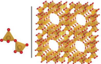
Zeolites are porous crystalline alumino-silicates, with a structure built around a regular arrangement of SiO4or AlO4tetrahedra linked together by their vertices as represented in figure1.2. The porous network created by these tetrahedra is very different from one zeolite to another, resulting in a wide variety of materials and properties. For examples, the pores can be linear, spherical or in a zigzag disposition; connected together through windows or independents. The International Zeolite Association[6] gives a three letter code such as LTA, FAU or SOD to each experimental crystalline structure. It is however mathematically possible to generate an infinite number of crystalline structures using tetrahedra as a building block, and there are databases of hypothetical zeolites with more than 2 million different frameworks[7].
Figure 1.2 – Two SiO4tetrahedra on the right, and the structure of zeolite LTA on the left. Si atoms are in yellow and oxygen atoms in red.
While pure-silica zeolites (SiO2polymorphs) are neutral, each aluminum atom in the structure introduces a negative charge as silicon is usually in the +IV oxidation state while aluminum is in the +III state. These charges are compensated in the material by a counter ion such as sodium Na+, potassium K+, calcium Ca2+or barium Ba2+. Each zeolite topology thus defines a family of materials with varying chemical composition. The general chemical formula for a zeolite is Mx/mAlxSi1–xO2, possibly with several different metal cation M. The Si/Al ratio can vary from 1 for structures with the most aluminum atoms to infinity for pure silica zeolites, also called zeosil. Each new aluminum atom replacing a silicon atom is accompanied by a cation to ensure the overall charge neutrality. The presence of these cations contributes to the remarkable adsorption and catalysis properties of zeolites. Zeolites are used in industrial processes for ions ex-change through their extra cations; catalysis through their high specific surface area and acido-basic properties; molecular sieves through the multiples pores sizes and tunable properties.
adsorption and intrusion in nanoporous materials
1.1.2 Metal–Organic Frameworks
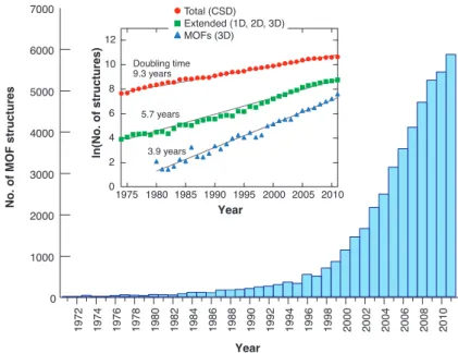
Metal–organic frameworks are a more recent class of crystalline nanoporous materials. The first works on these materials were made in the 90s by Richard Robson and collab-orators[8,9], but the systematic study of these materials only started in the 2000s. In 1999, the group of Omar Yaghi created MOF-5[10], a MOF with large permanent porosity (15 Å in diameter for the largest cavity) and chemical tunability, sparking interest in the international research community for these materials. Since then, the field of MOF has been developing exponentially, both in terms of the number of publications and in terms of number of structures reported in the literature. Figures1.3shows the growth of the number of structures in the Cambridge Structural Database, with a doubling time of 3.9 years for three-dimensional MOFs.
ln (N o. of st ru ct ur es ) Year Doubling time 9.3 years 5.7 years 3.9 years 2010 2005 2000 1995 1990 1985 1980 1975 12 10 8 6 4 2 0 No .o fM O F st ru ct ur es 7000 6000 5000 4000 3000 2000 1000 0 Year 20 10 20 08 20 06 20 04 20 02 20 00 19 98 19 96 19 94 19 92 19 90 19 88 19 86 19 84 19 82 19 80 19 78 19 76 19 74 19 72 Total (CSD) Extended (1D, 2D, 3D) MOFs (3D)
Figure 1.3 – Number of MOF structures in the Cambridge Structural Database showing an exponential growth. Reprinted with permission from AAAS, reference [11].
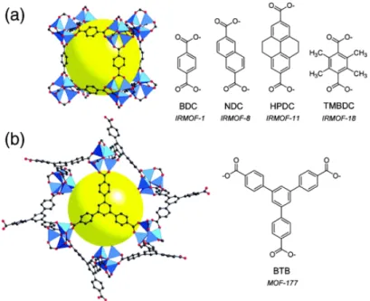
Materials in the MOF family are built around metallic centers, connected by organic link-ers, assembled into nano- or mesoporous crystalline structures (see figure1.4). Compared to zeolites, they can be synthesized in a solvent at lower temperatures (from ambient temperature to 200°C), by mixing metallic salts and organic linkers. Due to the presence of these organic linkers, MOFs have smaller thermal stability (up to 400°C) compared to the inorganic zeolites that can withstand up to 1000°C. Nevertheless, this reduced stability is made up for by the incredible adaptability of the MOFs. By combining the variety of linker-metal coordination chemistry with the adaptability of organic chemistry, they offer a huge number of different structures, and can be tuned for specific applications by changing linkers and/or metal centers. Figure1.5presents an example of how the shape and size of the pores can be adapted by changing the linker used. Furthermore, compared to zeolites which present a rigid crystalline structure, some MOFs grouped together under the name Soft Porous Crystals[12] have extraordinary structural flexibility in response to external stimuli[13–15].
1.1 nanoporous materials B A Zn4O(CO2)6 M3O3(CO2)3 (M = Zn, Mg, Co, Ni, Mn, Fe, and Cu) Ni4(C3H3N2)8 In(C5HO4N2)4 Zr6O4(OH)4 -(CO2)12 Zr6O8(CO2)8 M3O(CO2)6 (M = Zn, Cr, In, and Ga)
M2(CO2)4 (M = Cu, Zn, Fe, Mo, Cr, Co, and Ru) Zn(C3H3N2)4 Na(OH)2(SO3)3 Cu2(CNS)4 H2BDC H2BDC-X H4DOT (X = Br, OH, NO2, and NH2) H2BDC-(X)2 (X = Me, Cl, COOH, OC3H5, and OC7H7) H4ADB Fumaric acid Oxalic acid
H4ATC H3THBTS H3ImDC DTOA
ADP H3BTP TIPA Gly-Ala H4DH9PhDC H4DH11PhDC H3BTC Ir(H2DPBPyDC)(PPy)2+ H6BTETCA DCDPBN BPP34C10DA H3BTB (X = CH) H3TATB (X = N) H3BTE (X = C≡C) H3BBC (X = C6H4) H6TPBTM (X = CONH) H6BTEI (X = C≡C) H6BTPI (X = C6H4) H6BHEI (X = C≡C−C≡C) H6BTTI (X = (C6H4)2) H6PTEI (X = C6H4−C≡C) H6TTEI (X = C≡C-C6H4-C≡C) H6BNETPI (X = C≡C−C6H4−C≡C−C≡C) H6BHEHPI (X = (C6H4−C≡C)2) COOH COOH COOH COOH COOH COOH OH HO COOH COOH X COOH COOH X X COOH HOOC COOH HOOC O HO OOH N COOH HOOC N HOOC COOH N NH HOOC COOH NNH N HN HN N SO3H SO3H HO3S OH HO OH H2N NH2 S S N N N N N N N HOOC COOH COOH H N H N2 O COOH OH COOH HO COOH OH HO COOH COOH HOOC COOH X X X COOH HOOC COOH N N OH OH Cl Cl COOH HOOC COOH COOH COOH HOOC O O O O O COOH COOH O O O O O N N COOH COOH Ir N N + COOH HOOC COOH X X X COOH COOH HOOC COOH HOOC COOH X X X Al(OH)(CO2)2 VO(CO2)2
Figure 1.4 – Examples of inorganic clusters (A) and organic linkers (B) used in MOF synthesis. Reprinted with permission from AAAS, reference [11].
adsorption and intrusion in nanoporous materials
High diversity of structures
One of the main advantage of MOFs over other porous materials such as zeolites or activated carbons is the diversity of structures that can be built from the different available inorganic clusters and organic linkers (see figure1.4). With all the versatility provided by the coordination and organic chemistry, one is only limited by the thermodynamic and chemical stability of the structures obtained, and by the existence of a synthetic route to generate the porous polymorphs of interest, when another phase might be more stable. This diversity of structure gave rise to a design to applications approach, where one aims at producing the best structure for a given functionality. For example, researchers have reported MOFs with the highest methane[16] or hydrogen[17] uptakes until now.
Figure 1.5 – Examples of two MOFs built with a zinc oxide cluster with the same coordination geometry. (a) Structure of MOF-5, made with a linear linker. (b) Structure of MOF-177, made with a trigonal linker. Reprinted with permission from reference [18], copyright (2004) American Chemical Society.
They are two different approaches used to create new MOF structures. The first one is to use linkers and metallic centers with different connectivity, such as the ones shown in figure1.5. Most of the linkers used in MOF present either carboxylate or nitrogen organic functions that bind the metals. Using a linker with a different number of these functions or a metal center with different oxidation degree will create a new structure. The second way to create a new structure is by changing the chemical structure of the linker, while keeping the number and positions of binding functions intact. The resulting structures are said to be isoreticular, i.e. they share the same topology or net.
1.1.3 Zeolitic Imidazolate Frameworks
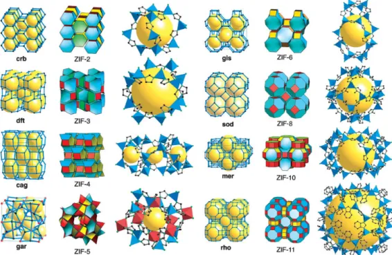
Zeolitic Imidazolate Framework or ZIFs are a family of MOFs built around tetravalent M2+ metal centers such as Fe, Co, Zn, Cd or Cu; linked together by imidazolate or function-alized imidazolate linkers. They present the same possible topologies as zeolites, with metal(imidazolate)2building blocks taking the role of SiO2 — as illustrated in figure1.6. The first ZIFs (ZIF-1 to ZIF-12) were synthesized in 2006[19], and found to be more
1.1 nanoporous materials O Si 145° Zn N N Si Zn
[ ]
im=imidazole C C H HFigure 1.6 – Illustration of the analogy between ZIFs and zeolite coordination. resistant to water and heat that typical MOFs, which made them interesting for commer-cial applications. This higher stability is due to the relatively strong metal–imidazolate coordination bond.
ZIF-8 is the member of the ZIF family which I worked on specifically during my PhD. It uses 2-methylimidazolate (mim) as a linker, and Zn2+as its metallic centers. ZIF-8 has formula Zn(mim)2 and adopts the sodalite (sod) topology. In this topology, large quasi-spherical pores corresponding to the sodalite cages are connected by windows formed by 6 and 4 zinc atoms. In ZIF-8, the 4 members windows are too small for any molecules to go through, and all of the connectivity of the pore space happens through the 6 members windows. I also studied materials derived from ZIF-8, where the methyl group of the linker is replaced by halogens such as chlorine or bromide. The corresponding studies are presented in sections4.2and5.1.
Figure 1.7 – Examples of ZIF structures. From left to right are the crystalline structure of a zeolite with the same topology, the crystalline structure of the ZIF and the biggest sphere inside the cages. Reprinted from reference [19], copyright (2006) The National Academy of Sciences of the USA.
adsorption and intrusion in nanoporous materials
1.1.4 Structural flexibility
In 1998, Susumu Kitagawa proposed a classification of MOFs in three categories[12] depending on their behavior with respect to molecule adsorption and desorption. The first category of materials has a non-permanent porosity, in the sense that if we remove the solvent molecules from the structure after the synthesis, the material collapses. The second category regroups materials that have a strong enough crystalline structure and keep the same porosity during adsorption and desorption. They are essentially rigid, and generally present a very good mechanical and thermal stability. The last category contains materials that retain porosity when the synthesis solvent is removed, but may deform and change shape during adsorption. Materials in this last category are called Soft Porous Crystal, and have a flexible, dynamic structure that can change under external stimuli such as mechanical pressure, adsorption, temperature, or even exposure to light[13,15].
intraframework
dynamics negative thermal expansion
swelling gate opening T➚ V ➘ ZIF-8 IRMOF-1 MIL-88 solvent +guest: V➚ Cu(4,4′-bipy)(dhbc)2 MIL-53 breathing
Figure 1.8 – Illustration of the main flexibility modes of MOFs: linkers rotation, thermal expansion, swelling, gate opening and breathing. Reprinted with permission from reference [20], copyright (2011) Wiley.
This flexibility is inherent to the hybrid organic-inorganic nature of MOFs. Indeed, their structure is based on both strong covalent bonds inside the organic linkers, and weaker bonds such as coordination bonds, π-stacking of linkers, hydrogen bonds, etc. These weaker bonds can vary locally in length or orientation, inducing large scale deformations of the materials. Possible deformation modes for MOFs are represented in figure1.8. All MOFs are flexible to some extent through local deformations, such as linkers rotation, this type of flexibility happening without any global framework deformations. The other types of flexibility only occur in specific materials. For example, we observe in some materials a volume contraction as they heat up, i.e. a called negative thermal expansion[21]. In soft porous crystal, we additionally observe large scale deformations of the structure. For some materials, the whole structure will swell in presence of a solvent. For example, the volume of MOFs of the MIL-88 family can grow by more than 200% of the initial
1.1 nanoporous materials
volume in presence of lutidine[22]. Other MOFs present multiple stable phases, and can switch from one phase to another under external stimuli. The gate opening phenomenon is one of such transitions, between an initially non-porous structure to a more open and more porous structure through the movement of linkers or the displacement of a sub-network. Materials from the MIL-53 family present two transitions, from an open to a close-pore phase, and then back to an open-pore phase[23] under continuous gas loading increase, creating a breathing-like behavior.
1.1.5 Industrial applications
Zeolites enjoy a wide range of applications, from air separation using pressure swing adsorption[24], catalysis in oil refining[25], wastewater cleaning and heavy metal removal [26], capture of radioactive particles[27], molecular sieve[28], and even laundry detergent [29]. Each year, almost 3 million tonnes of zeolites are produced or extracted for these applications. MOFs are still relatively new, and don’t enjoy as many commercial and industrial applications as zeolites yet. One of the obstacles to wider usage of MOFs is their price, as they can be a hundred times more expensive than zeolites. In the following, I will give examples of potential applications of MOFs in various fields.
Gas separation, purification, and storage
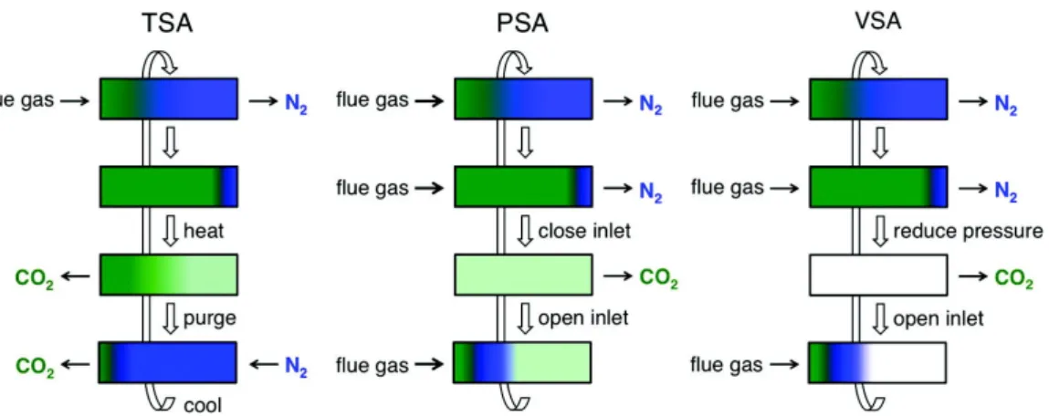
Gas separation and purification processes are at the root of the chemical industry, either generating small carbon chain molecules from oil and natural gas, separating oxygen from nitrogen in the air, or CO2from H2 during ammonia production. Current best estimates indicate that gas separation accounts for 10-15% of the energy consumed globally[30]. Furthermore, when faced with climate change resulting from continually-increasing anthropogenic CO2 emissions, optimization of storage and separation processes is in-creasingly critical. There are nowadays multiple techniques used for gas separation using cryogenic separation, liquid phase adsorption or gas phase adsorption. Few techniques based on gas phase adsorption are illustrated in figure1.9.
Figure 1.9 – Schematic diagrams of temperature swing adsorption (TSA), pressure swing adsorption (PSA), and vacuum swing adsorption (VSA) processes for regenerating solid adsorbent in a fixed-bed column. Reprinted with permission from reference [31], copyright (2011) American Chemical Society.
As porous materials with huge specific surface area, MOFs look like ideal candidates for any application involving gas adsorption. Separating gases by adsorption requires different interactions between the porous material and the different adsorbates. These
adsorption and intrusion in nanoporous materials
interactions can be tuned in MOFs by changing the linkers and modifying the pores size, shape and chemical properties. During gas purification, one chemical species is present in majority (the gas to purify) and we try to remove the remaining impurities. For example, HKUST-1 (a MOF with formula Cu3(btc)2) turned out to be very efficient to remove sulfur compounds such as tetrahydrothiphene and thiophene from natural gas, thanks to the formation of a Cu – S bond[32]. It was able to adsorb 70 g of tetrahydrothiphene by liter of material, which is noticeably better than the standard materials used in the industry (less than 10 g/L for activated carbons).
Considering gas storage, an emerging application is the storage of hydrogen gas for energy generation and automobile transportation. Historically, hydrogen has been stored through liquefaction or compression in bottles and tanks, but these approaches have security and cost issues. MOFs are interesting as safer media for gas storage because they are able to pack the hydrogen molecules densely at a lower pressure. For example, Ni2(m – dobdc) is one of the current best candidate for H2storage, able to adsorb 11 g/L of H2 at ambient temperature, and up to 23 g/L via a temperature swing from -75°C to 25°C[33].
Heterogeneous catalysis
Figure 1.10 – Post-synthetic modifications of ZIF-8 to synthesize SALEM-2 and obtain catalytic activity. Reprinted with permission from reference [34], copyright (2012) American Chemical Society.
Heterogeneous catalysis is used in numerous industrial processes. The selectivity of these catalytic processes is often based on the shape and size of the reacting species, hence the interest in using catalysts with a regular and uniform porosity. Porous crystalline materials are especially interesting in this regard. Moreover, since catalysts can be re-used, and only small quantities of them are needed, the advantages of MOFs can offset their cost. The possibilities to create chiral MOFs using enantiomerically pure linkers, or conformational chirality[35] also opens the way to asymmetric catalysis.
A first strategy for using MOFs as catalysts involves the metallic centers, which can have a catalytic activity of their own. For example, MIL-100(Fe) and MIL-100(Cr) have an interesting activity for the Friedel–Craft benzylation reaction, used for the production of linear alkyl-benzene; surpassing the activity of the HBEA and HY zeolites traditionally used[36]. HKUST-1 MOF can be activated after the synthesis by removing an apical water
1.1 nanoporous materials
molecule, creating a very reactive Lewis acid site which can be used for cyanosilylation reactions[37].
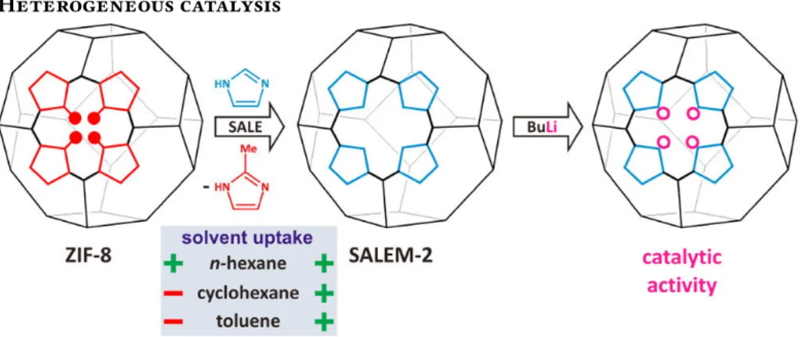
Another approach for adding catalytic activity to MOFs entails adding functional groups to the linkers with the desired activity. For example, SALEM-2 can be activated with n-butyllithium and exhibits a strong Brønsted base catalytic activity[34] (see figure1.10). Around the same idea, the amino functions of IRMOF-3 and amino-MIL-53 make them suitable as basic catalysts for the Knoevenagel condensation of ethyl-cyanoacetate and ethyl-acetoacetate with benzaldehyde[38].
Chemical sensors Excitation Excitation Strong Emission uenched Emission Explosive
Figure 1.11 – Schematic representation of optical properties modifications of Zn2(bpdc)2(bpee) MOF. Image adapted with permission from reference [39], copyright (2009) Wiley.
Some MOFs have luminescent properties, linked either to the presence of aromatic or functionalized linkers or a metal cation from the lanthanide group. These luminescent properties, combined with the adsorption capabilities of MOFs open the possibility of using MOFs as chemical sensors. The structural and/or electronic transition of a MOF upon adsorption will modify the light emission properties of the material, allowing to detect specific gaseous compounds. This is have been developped in particular to detect explosive materials at low concentrations. For example, the Zn2(bpdc)2(bpee) MOF is able to detect multiple nitro-substituted molecules found in explosives such as 2,4-dinitrotoluene or 2,3-dimethyl-2,3-dinitrobutane in around 10 s[39] (see figure1.11). Another example is the [Zn2(oba)2(bpy)]3MOF, also able to detect explosive and aromatic molecules through a fluorescence quenching phenomenon[40].
adsorption and intrusion in nanoporous materials
1.2
Adsorption and intrusion
Adsorption is an interface phenomenon, where molecules or atoms are depositing and creating a thin film at the surface of a material. Because they have a high specific surface area, the adsorption in porous materials is several orders of magnitude higher than on the external surface of bulk materials. Adsorption is used as a characterization technique for porous media, and is also the basis of their most prevalent applications.
1.2.1 Adsorption of gases
It is possible to study adsorption both with experimental and theoretical approaches. The central tool for the study of adsorption is the single component adsorption isotherm. Considering a pure gas adsorbing in a porous matrix, the adsorption isotherm records the amount of adsorbed gas (also called loading) at a fixed temperature as a function of the pressure P, or the more commonly, the pressure relative to the vapor pressure of the gas P/P0. Experimentally, these adsorption isotherms are obtained with gravimetric, volumetric or chromatographic methods[41,42].
Figure 1.12 – IUPAC classification of isotherms.
The IUPAC classifies adsorption isotherms depending on their shape, as represented in figure1.12[43]. Only the isotherms of type I, IV and V can occur in nanoporous solids. Type I isotherms are concave, reversible and the adsorbed quantity of matter goes to a finite value as the pressure increases. It is the most common isotherm type, and express the prevalence of gas–solid interactions over gas–gas interactions in a material containing a single kind of equivalent adsorption sites.
Type IV isotherms also present a maximal loading, and one or two steps with sometimes a hysteresis loop between the adsorption and desorption branches. These steps are usually attributed to a modification in the structure of the adsorbing solid[29]. Type V isotherm shows an inflection point: at low pressure the adsorption is very low, mainly due to small gas–solid interactions. For higher pressures the adsorption becomes stronger thanks to interactions between the gas molecule themselves. In flexible porous materials, type IV isotherms would be associated with breathing materials, and type V isotherms with gate
1.2 adsorption and intrusion
opening. Finally, isotherms types II, III and VI do not present a maximal loading, and are usually observed in solids with multiple pore sizes and a continuous transition from mono-layer adsorption to multi-layers adsorption and capillary condensation.
It is possible to study and predict adsorption isotherms using theoretical methods such as thermodynamic models and molecular simulations methods such as Grand Canonical Monte Carlo. I will present with more details the methods I used during my PhD to study adsorption in the corresponding chapters: chapter2for macroscopic thermodynamics modeling; and chapter3for molecular simulations.
1.2.2 Intrusion of liquids
The intrusion of liquids, and in particular mercury, has been used for a long time to characterize porous materials having pore widths in the macropore range of 50 nm to 500 µm[44]. Intrusion can be seen as adsorption of fluids above the vapor pressure (P > P0), i.e. when the fluid is in its liquid state. A sketch of an intrusion–extrusion porosimeter is given in figure1.13. In this device, a non-wetting fluid is pressurized and will enter the porous network at a pressure linked to the pore width h by the Washburn equation[45]:
P = 2γ cos θ
h , (1.1)
where γ is the surface tension of the liquid/gas interface, and θ the angle of contact along the triple line solid/liquid/gas.
∆V
P
pressure transmitting fluid non-wetting liquid porous solidFigure 1.13 – Sketch of an intrusion–extrusion porosimeter. A sample of porous solid powder is placed in a non-wetting liquid (in blue) and pumps control the pressure of a pressure-transmitting fluid (in yellow). A manometer records the pressure P during the experiment, and a transducer records changes in volume of the system.
adsorption and intrusion in nanoporous materials
In the 2000s, water was used as non-wetting fluid in an adapted porosimetry device to characterize hydrophobic nanoporous materials such as silica gels[46] and siliceous zeo-lites[47,48] or micelle-templated silica[49]. More recently, forced wetting of electrolyte solutions was studied, disclosing very interesting giant osmotic pressure effects[50,51]. Water can only be used as a non-wetting fluid in hydrophobic solid, where the potential energy interaction between the water molecules and the confining solid wall is much weaker than the water molecules’ mutual interaction. This use of water as a non-wetting fluids opened a new field of applications for the intrusion in nanoporous solids based on mechanical energy storage and dissipation[45,47]. Interested readers can consult the review I helped to write on the subject, published in Chemical Society Reviews (2017)[45], for more details.
The general idea of storing energy by forced intrusion of a non-wetting fluids in porous media was first explored by Fadeev et al. some years ago[46]. In 2001, Eroshenko et al.[47] reported a stepwise intrusion-extrusion isotherm of water in two different hydrophobic zeolites, namely zeolite β and silicalite-1 at pressures around 60 and 80 MPa respectively, i.e. notably above the water saturation pressure of 3500 Pa at room temperature.
Figure 1.14 – Pressure-volume intrusion isotherms of water in (1) zeoliteβ; (2) silicalite-1
(OH–); (3) silicalite-1 (F–) and (4) Na-ZSM-5. Reprinted with permission from reference [47], copyright (2001) American Chemical Society.
The reported intrusion isotherms are reproduced in figure1.14. From these results, the authors proposed that it was possible to use these heterogeneous systems to “accumulate, restore and dissipate mechanical energy”, thus opening new routes in the field of energet-ics. In terms of energy storage devices, a system displaying an intrusion-extrusion cycle without hysteresis can simply be termed as a spring. A system with hysteresis is a shock absorber and an incomplete cycle in which water is retained in the porous framework upon pressure release can be called a bumper (see also the figure5.1for an illustration of these behaviors).
Patarin and coworkers[53,54] were the first to show that the intrusion pressure in silicalite-1 was increased by a factor of 3 when using a concentrated solution of lithium
1.2 adsorption and intrusion
Figure 1.15 – Intrusion and extrusion pressures for NaCl solutions of various concentrations in ZIF-8 at 323 K. The inset displays intrusion–extrusion curves, plotted not in absolute pressure P but as a function of P – 2cRT, showing that the effect of concentration is well explained by the van ’t Hoff osmotic pressure. Reprinted with permission from reference [51], copyright (2015) American Physical Society.
Figure 1.16 – Intrusion-extrusion process in β zeosil. With pure water, it behaves like a
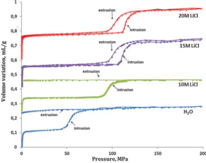
bumper. As the LiCl concentration increases, the intrusion pressure is enhanced and a change in behavior from bumper to shock-absorber is observed from 10 M to 15 M of LiCl. Reproduced from reference [52], with permission from the PCCP Owner Societies.
adsorption and intrusion in nanoporous materials
chloride, instead of pure water. Consequently, the stored energy was also increased by the same factor, which seems very promising in view of potential energy storage applications. This has lead to a number of such aqueous solutions intrusion-extrusion studies in various zeosils as well as hydrophobic ZIF materials. In addition to the effect of increasing the intrusion pressure, the use of electrolyte solutions can lead to a drastic change in the intrusion-extrusion behavior. Ryzhikov et al.[52] showed that β-zeosil changed its behavior from bumper to shock-absorber, as the LiCl concentration increased from 10 mol/L to 15 mol/L. This is shown in figure1.16.
Intrusion of electrolyte solutions in ZIF-8 was recorded using several concentrations and different electrolytes[51,55]. In all cases, the intrusion pressure increased as the electrolyte concentration increased and the intrusion-extrusion cycles were shifted repli-cas of the pure water cycles. Based on the findings of a molecular dynamics study[56], Michelin-Jamois suggested that only pure water was intruded in the material’s pore. According to this hypothesis, the shift in intrusion pressure is due to the osmotic pressure, i.e. the difference in pressure between the pure water pressure inside the pore and the aqueous solution pressure outside the porous framework. A simple application of the van’t Hoff osmotic equation (Π = icRT) confirmed this model in most of the studied cases, as illustrated in figure1.15.
Even more recently, Arletti et al.[57] coupled intrusion-extrusion experiments of MgCl2 aqueous solution to in situ high-pressure synchrotron X-ray diffraction analysis. This study clearly demonstrated the presence of both ions and water molecules in the high pressure intruded liquid. During my PhD, I approached the question of when and why ions in the aqueous solution enter the microporous frameworks using classical molecular simulations, the corresponding work is presented in chapter5.
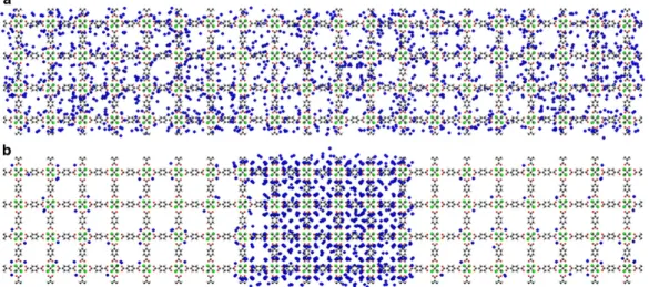
Figure 1.17 – Snapshots of molecular dynamics simulations of benzene in MOF-5 at (a) 125 K and (b) 50 K. At 50 K, vapor–liquid coexistence takes place, the vapor and liquid phases extending over many unit cells. Adapted with permission from reference [58], copyright (2015) Wiley.
1.2 adsorption and intrusion
1.2.3 Coupling adsorption and deformations
Adsorption and intrusion in flexible nanoporous materials can present very interesting behaviors. First, some materials deforms during adsorption, creating the aforementioned effects of breathing, gate opening or even negative gas adsorption[59]. At the same time, because they are constrained by the surrounding porous solid, fluids inside the pores adopt different static organization and dynamic behavior than fluids in the bulk state. These effects of the porous solids on the fluids are grouped together under the category of confinement effects.
Confinement effects introduce another way to look at adsorption and intrusion: two different phases of the same chemical species are at equilibrium, and transfers from one phase to the other occurs as the fluid enters or leave the porous structure. In some cases, there can even be multiple different fluid phases inside the porous volume. Recently, Braun et al.[58] demonstrated, using NMR relaxometry and molecular dynamics, that a true liquid–vapor coexistence existed in fluid benzene confined in MOF-5. The liquid and vapor phases were shown to extend over many unit cells thanks to the open 3D framework, as shown in figure1.17.
While confinement effects also occurs in rigid nanoporous material, when working with flexible nanoporous materials we need to consider multiple phases equilibrium occurring at the same time. The fluid phase equilibrium between the bulk state and the confined state can have an influence on phase equilibrium between the porous material phases and reciprocally.
During my PhD work, I explored confinement effects mainly in ZIF-8, with different fluids: gaseous nitrogen at 77 K in chapter4, and aqueous solutions at ambient temperature in chapter5. I also looked at more rigid systems — namely aluminosilicate nanotubes — in chapter5.2. I have been particularly interested in the simulation methods one can use to study the coupling between adsorption and deformations in flexible nanoporous materials.
2
M A C R O S C O P I C S T U D I E S
2.1 Classical thermodynamics . . . 24 2.1.1 First law of thermodynamics . . . 24 2.1.2 Second law of thermodynamics . . . 25 2.1.3 Thermodynamic ensembles . . . 25 2.1.4 Ensembles for adsorption processes . . . 26 2.2 Macroscopic calculations for gas separation in flexible materials 28 2.2.1 Ideal Adsorbed Solution Theory . . . 29 2.2.2 IAST and flexible frameworks . . . 30 2.2.3 Osmotic Framework Adsorbed Solution Theory . . . 32 2.2.4 Comparing IAST and OFAST . . . 34 Conclusions . . . 41
A first way to approach the problem of coupled deformation and adsorption in porous materials is through the use of macroscopic or thermodynamic modeling methods. Such methods are based on classical thermodynamic principles and allow us to gain high-level understanding of the processes at play. In this chapter, I will introduce the concept of thermodynamic potential and thermodynamic ensemble, that can be used together to predict the evolution of a system. In a second part, I will show how these thermodynamic potentials can be used to make predictions on the co-adsorption of multiple gases in the same porous framework, but that one needs to be careful to use the thermodynamic ensemble adapted to the problem at hand.
macroscopic studies
2.1
Classical thermodynamics
2.1.1 First law of thermodynamics
The starting point for the macroscopic methods I will describe here are the laws of thermodynamics. The first law of thermodynamics is a generalization of the conservation of energy during physical processes. It can be stated as follows:
For a closed system, the change in energy between two states of internal thermodynamic equilibrium is the sum of the work of external forces and the heat received by the system.
If we divide the total energy Etotof a system into its kinetic energy Ekin, potential energy Epotand internal energyU, and letting W be the work received by a system during a transformation and Q the heat transfer during the same transformation, the first law of thermodynamics can be written as
∆Etot= ∆Ekin+ ∆Epot+ ∆U = W + Q. (2.1) If now we consider a system at rest in a constant external potential field, Ekinand Epotare constant, and we find the usual formulation of the first law of thermodynamics:
∆U = W + Q. (2.2)
It is often interesting to use a differential formulation of this relation, considering in-finitesimal changes inU, W, and Q:
dU = δQ + δW. (2.3)
If the system composition is not constant, i.e. if it is undergoing chemical reactions or if the system is open and exchanges particles with an external reservoir, we need to add another term depending on the quantity of matter {ni} for each chemical species in the system:
dU = δQ + δW +
∑
i
µidni. (2.4)
In this formulation, the µiare called the chemical potentials; they represent the relative stability of the different chemical species in the system.
An interesting special case is that of an external pressure acting on the system. In this case,
δWpressure= –pextdV ; (2.5)
where pextis the external pressure. If pextis constant during the transformation, this can be written as δWpressure = –d(PV), using P as the constant value of the pressure. We can then define the enthalpy H as H =U+ PV ; which allow us to rewrite equation (2.4) as
dH = δQ + δWother+
∑
iµidni. (2.6)
Here, δWotheris the work coming from all forces excluding pressure forces.
2.1 classical thermodynamics
2.1.2 Second law of thermodynamics
The second law of thermodynamics allows us to make predictions on the “natural” evolution of a system.
There exist a function of state called entropy, which is an increasing func-tion of time for any transformafunc-tion of an isolated system.
The variation of entropy, noted S, during a transformation of a closed but non isolated system can be linked to the heat transfer between the system and its surroundings by the Clausius relation:
∆S = Q
T+ Screated. (2.7)
The Q/T term is homogeneous to entropy and called the exchanged entropy, and is the entropy given to the system by its surroundings. Screatedis the entropy created during the transformation, and is a positive quantity by the second law of thermodynamics. When Screatedis null, the transformation is said to be reversible.
Using the relations (2.4) and (2.7); and considering that only the pressure forces act on the system, we can extract an evolution principle for any transformation:
TdS = δQ + TδScreated (2.8) TdS = (dU– δW –
∑
i µidni) + TδScreated (2.9) dU+ PdV –∑
i µidni– TdS = –TδScreated. (2.10) If there is a function Φ such as dΦ = dU+ PdV – ∑iµini– TdS, then for any transfor-mation of a closed system, dΦ = –TδScreated ≤ 0. This means that Φ is a decreasing function of time, and it will be minimal in the equilibrium state. In this case, Φ is called a thermodynamic potential.2.1.3 Thermodynamic ensembles
A thermodynamic ensemble is defined by a set of thermodynamic state variable that obey some constraints. For example, the ensemble where the composition of the system is fixed, together with the volume and total energy is called the NVE or microcanonical ensemble. Other well-known ensembles present a fixed pressure or temperature: the NVT or canonical ensemble, and the NPT or isobaric-isothermal ensemble.
Each of these ensembles has an associated thermodynamic potential. For the microcanon-ical ensemble, we start with equation (2.10):
dΦ = dU+ PdV –
∑
iµidni– TdS. (2.11)
dUand dV will be zero as the energy and volume is constant. Moreover as the system composition is fixed, dni = 0. This gives
dΦ = –TdS≤0. (2.12)
macroscopic studies
The thermodynamic potential for the NVE ensemble is the negentropyN ≡–TS, which will be minimal (and the entropy will be maximal) at equilibrium.
If we now allow the energy to change but fix the kinetic energy and thus the temperature by the mean of an external thermostat, equation (2.10) becomes
dΦ = dU+ PdV –
∑
i µidni– TdS – (SdT – SdT) (2.13) dΦ = dU+ PdV –∑
i µidni– d(TS) + SdT. (2.14) As the temperature, volume and composition are fixed, dT = dV = dni= 0, which means thatdΦ = d(U– TS). (2.15)
We can introduce the Helmholtz free energy F≡ U– TS (sometimes simply called free energy), which is the thermodynamic potential in the NVT ensemble.
If now we allow the volume to change in the system, while fixing the pressure with a barostat and keeping the temperature fixed, equation (2.10) becomes
dΦ = dU+ PdV + (VdP – VdP) – TdS – (SdT – SdT) –
∑
i µidni (2.16) dΦ = dU+ d(PV) – d(TS) – VdP + SdT –∑
i µidni (2.17) Again, as the pressure, temperature and composition are fixed, this reduces todΦ = dU+ d(PV) – d(TS). (2.18)
We define the Gibbs free energy G as G≡ U+ PV – TS≡F + PV≡H – TS, which is the thermodynamic potential in the NPT ensemble.
2.1.4 Ensembles for adsorption processes
Getting back to the topic of adsorption in porous material, we need to describe the thermodynamic ensemble in which the adsorption process takes place. The temperature is always fixed, as well as the composition of the adsorbing host. If the host is rigid, and does not deform under adsorption, then we can consider that the volume of the system is constant. The main difference with the previously defined ensembles is that the composition of the gas phase is not fixed: the number of gas molecules adsorbed in the system is allowed to change during adsorption. In this case, equation (2.10) becomes
dΦ = dU– d(TS) + PdV + SdT –
∑
iµidni (2.19)
Removing the null terms dV and dT, we find the definition of the grand-canonical ther-modynamic potential Ψ, associated with the µVT ensemble:
Ψ≡ U– TS –
∑
iµini≡F –
∑
i
µini. (2.20)
The Gibbs-Duhen relation (VdP – SdT = ∑inidµi) also gives us:
Ψ= –PV (2.21)
2.1 classical thermodynamics
If we now consider adsorption in a flexible host, the volume is no longer fixed. Instead, in most experimental setups, external pressure is fixed and set equal to the pressure of the adsorbed gases outside of the host. The thermodynamic ensemble suited for the study of adsorption in flexible materials is called the osmotic ensemble, first introduced in 1994[60] for the study of fluid mixtures, and adapted to multi-components phase equilibrium in 1998[61]. In this ensemble, the pressure, temperature, number of atoms of the host phase Nhostare fixed, as well as the chemical potential of the adsorbed species. Again, starting from equation (2.10)
dΦ = dU– d(PV) – d(TS) – VdP + SdT –
∑
iµidni. (2.22) As usual, dT and dP are null as the corresponding variable is fixed. In the sum over the
µiniterms, only the adsorbed species quantities of matter are allowed to change. The osmotic potential is thus defined by
Ω≡ U– TS + PV –
∑
i µini≡F + PV –∑
i µini≡G –∑
i µini (2.23) This potential will be the basis we use to predict co-adsorption in flexible porous me-dia in the next section. The table 2.1presents a summary of all the thermodynamic ensembles discussed so far, as well as the associated fixed quantities and thermodynamic potentials.Ensemble Fixed quantities Thermodynamic potential
microcanonical N, V, E N ≡ –TS
Canonical N, V, T F ≡ U– TS
Isobaric-Isothermal N, P, T G ≡ H – TS Grand-Canonical µi, V, T Ψ ≡ F – ∑iµini Osmotic Nhost, µi, P, T Ω ≡ G – ∑iµini
Table 2.1 – Thermodynamic ensembles and associated thermodynamic potentials
macroscopic studies
2.2
Macroscopic calculations for gas separation in
flexible materials
Gas separation is an important step in multiple industrial processes, from separation of hydrocarbons in oil chemistry, to CO2 separation and storage or oxygen extraction in the air. The two main methods used for gas separation are cryogenic distillation, mainly used for air separation, and differential adsorption. Adsorption-based processes for gas separation, which rely on microporous materials in the form of an adsorber bed, are very versatile because of the large choice of materials available — and the possibility to tune them for a specific gas system. To choose an adsorber and the size of a production plant for the separation of a gas mixture, good knowledge on the co-adsorption of these gases in the candidate porous adsorbent is required.
Experimental characterization of this co-adsorption is typically done through multi-component gas adsorption studies. This problem is inherently high-dimensional, e.g., for a ternary mixture there are four variables to vary (temperature, total pressure, and two independent variables for the mixture composition). Because such experimental studies of co-adsorption equilibrium thermodynamics are typically long and expensive, there has been a great expense of literature devoted to theoretical models for the prediction of mixture co-adsorption based on single-component adsorption data. The most commonly used method in the field is the Ideal Adsorbed Solution Theory (IAST)[62], which is relatively simple to implement and robust, and allows the prediction of multi-component adsorption behavior from individual single-component isotherms. Other theories are used when the ideality of the system can no longer be assumed: non-ideal adsorbed solution models[42,63], the vacancy solution theory (VST)[64], the Real Adsorbed Solution Theory [65] (RAST), etc.
Materials which undergo large-scale reversible structural transitions impacting their total volume or internal pore volume appear to be particularly common among metal-organic frameworks based on relatively weaker bonds (coordination bonds, π–π stacking, hydrogen bonds, or some covalent bonds) compared to inorganic dense nanoporous materials (such as zeolites). In particular, some of these materials show transitions between an open phase with large pore volume, and a condensed or narrow pore phase with smaller pore volume — or, in some cases, no microporosity at all. Such transitions, known as gate-opening[66–68] or breathing[23] depending on the order in which the phases occur upon adsorption, can lead to stepped adsorption isotherms for pure components. In recent literature, many authors have relied on IAST predictions to predict that several such flexible MOFs would present very good selectivity for gas separation. In some cases, the authors explicitly used IAST to derive such predictions on flexible materials[69–72]. In other cases, IAST was not used explicitly, but the assumptions made for the behavior of mixtures stem from the classical understanding of selectivity rules in rigid materials, and would not necessarily be valid in flexible materials[73–78].
IAST is one of the available methods for direct macroscopic calculations and predictions, taking macroscopic data in the form of pure component adsorption isotherms and pre-dicting macroscopic co-adsorption isotherms. In practice, using IAST is akin to working in the Grand-Canonical ensemble, but we showed in the previous section that when the
2.2 macroscopic calculations for gas separation in flexible materials
adsorption host is flexible, one should use the Osmotic ensemble. Instead, an alternative method called the Osmotic Framework Adsorbed Solution Theory (OFAST)[79], based on the Osmotic ensemble, should be used when structural transitions occur during ad-sorption. This theory has been developed in the group[80,81], and takes into account the coupling between adsorption and deformations in flexible porous materials.
In this section, I will compare the results of IAST and OFAST on two sets of adsorption data from the published literature on gate-opening materials, and show that the IAST method gives unrealistic results: it does not reproduce the gate-opening behavior upon mixture adsorption, and overestimates the selectivity by up to two orders of magnitude. All of this work is published in Adsorption (2018)[82].
2.2.1 Ideal Adsorbed Solution Theory
The Ideal Adsorbed Solution Theory (IAST) starts by assuming that for a given adsorbent and at fixed temperature T, the pure-component isotherms ni(P) for each gas i of interest is known. Then, given a mixture of ideal gases adsorbing at total pressure P in a host framework and the composition of the gas phase yi — such that the partial pressures follow the ideal mixing law Pi = yiP — the goal of the method is to predict the total adsorbed quantity ntotand the molar fractions xiin the adsorbed phase.
In order to do so, Myers et al.[62] introduced for each mixture component a quantity homogeneous to a pressure, P∗i. The IAST method links this pressure to the compositions of the gas and adsorbed phases by defining a link between P∗i and the known variables:
Pyi = P∗ixi; (2.24)
and by imposing the equality of chemical potentials at thermodynamic equilibrium:
∀i, j Z P∗i 0 ni(p) p dp = Z P∗j 0 nj(p) p dp. (2.25)
In the simpler case of two-component gas mixture containing gases B and C, these two equations and the conservation of matter can be rewritten as a set of four equations:
PyB= P∗BxB xB= PC∗– P P∗C– P∗B 1 ntot = xB nB(P∗B) + 1 – xB nC(P∗C) Z P∗B 0 nB(p) p dp = Z P∗C 0 nC(p) p dp (2.26)
Solving these equations for P∗Band P∗Cwill give all the information on the system compo-sition. It can be done with either numerical integration of the isotherms, or by fitting the isotherms to a model, and then integrating the model analytically.
macroscopic studies
2.2.2 IAST and flexible frameworks
The original derivation of the IAST equations[62] by Myers et al. highlights three hy-potheses on the co-adsorption process on which the model is built:
(H1) The adsorbing framework is inert from a thermodynamic point of view;
(H2) The adsorbing framework specific area is constant with respect to temperature and the same for all adsorbed species;
(H3) The Gibbs definition of adsorption applies.
While the meaning of the last assumption (H3) has been diversely interpreted by different authors, Myers originally meant[62] and later confirmed[83] it to qualify the method by which the adsorption isotherms are measured. There is consensus on the fact that absolute adsorption should be used in IAST calculations — as opposed to excess or net adsorption[84]. This assumption thus applies equally to both rigid and flexible adsorbents. However, the first two hypotheses are not valid for flexible nanoporous materials. (H2) is clearly invalid, as modifications in both the host’s volume and internal structure lead to variations of pore size and specific area upon structural transitions. We note here, in passing, that (H2) should already be ruled out for systems of pore size close to the adsorbate diameter, as well as gas mixtures of widely different size or shape. It should, for example, not apply to molecular sieves systems, yet those can often be described reasonably well by IAST in practice. Finally, (H1) is violated by all the systems that feature adsorption-induced deformation, and in particular by systems presenting gate-opening or breathing behavior. As a conclusion, IAST has no theoretical foundation for those systems and should not be used for co-adsorption prediction in flexible nanoporous frameworks. uptake pressure closed open closed open ∆n
Figure 2.1 – Typical single-component isotherms for adsorption of two gases (red and blue) in a material with gate-opening. The gate-opening pressure is not the same for the two adsorbates, creating a pressure range with a high difference in the adsorption capacity for single-component isotherms (gray zone in the figure). Contrary to intuition, selectivity will not necessarily be high in this pressure range, but will depend on the difference in saturation uptake ∆n.
Aside from the mathematical treatment and thermodynamic hypotheses, we can show in a qualitative way why it is not possible, in flexible host frameworks, to use the single-component isotherm directly to predict multi-single-components adsorption. We address here