A
G
E
NG
EurAgEng
BUDAPEST2002
Paper Number:
Title:
Authors:
Summary:
02-PM-019
Development of a Multibody Model of a Sprayer
Ooms D., Lebeau F., Maton N., Destain M .-F.
Unité de Mécanique et Construction, Gembloux Agricultural University, 2 Passage des Déportés, 5030 Gembloux (Belgium), tel 32 (0)81 62 21 64, email :
A multibody model of a sprayer boom including the suspension was developed by using ADAMS 11.0 (Mechanical Dynamics).
The model was designed with the aim to describe the dynamic behaviour of different types of booms and suspensions (double trapezium, trapezium, pendulum, …). This was obtained by creating a general model in which geometrical (dimensions) and mechanical parameters (mass and inertia, friction coefficients, stiffness and damping coefficients of the hinges, …) of the system were easily modified. A graphical interface especially designed authorised this easy modification.
The validation of the model was obtained by measuring in real conditions the frame movements as solicitations and the boom movements as responses. The method was applied on a trailed sprayer equipped with a boom of 24 m and a trapezoidal suspension. Good accordance was found between measured and simulated vertical displacements.
The model may decrease the development costs of suspension and boom designs. The manufacturers who develop their sprayers with a 3D-CAD software should take more advantage of such a model.
1. Purpose
The accuracy of pesticides distribution is influenced to a large extent by boom movements. Vertical movements of the boom affect the deposit density both along and across the vehicle’s track, due to the changing spread of the spray with changing height. Variations in the horizontal component of the velocity of the boom cause fluctuations in the deposit density along the track.
The purpose of this research is to develop a multibody boom model (MBM) including the suspension. The model must predict the movements of the boom under any form of real movement imposed to the sprayer’s frame. Indeed, the combination of a MBM and a spray pattern simulation model (like that proposed by Lebeau et al., 2002) offers the possibility to evaluate the spray coverage inhomogeneity resulting from the boom movements. With this methodology, accurate criteria will be available to improve the boom design.
2. Method of Approach 2.1. Building general model
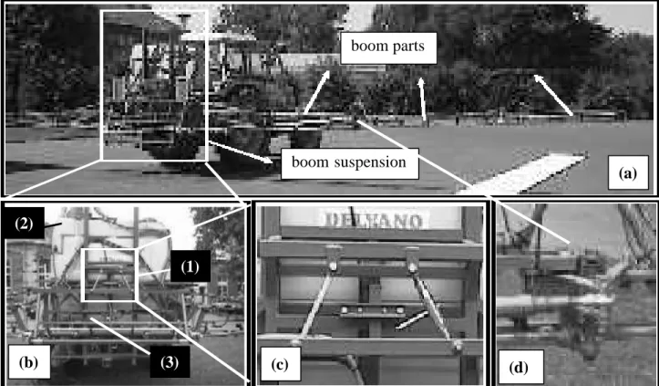
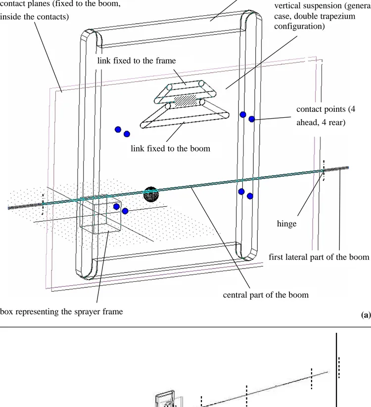
In the following text, the general model is called GMM (general multibody model) to make the difference with a particular model adapted to a specific sprayer. A GMM of a sprayer boom and its suspension was developed with ADAMS 11.0 (Mechanical Dynamics). By introduction of appropriate parameters, it gives the opportunity to model most existing sprayers. It can predict the displacement, speed or acceleration, linear or angular, of any part of the boom, while the sprayer frame is moving (any kind of movement can be imposed to this latter). Fig.1. shows a mounted sprayer and its main components, while Fig. 2. Indicates the structure of the GMM. It contains a symbolic transcription of the real parts : the suspension, the contact points, the boom parts and their hinges.
1. General suspension
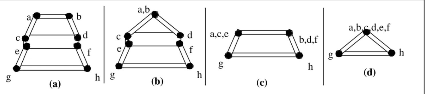
Fig. 3 presents the configuration of the most common suspensions. The links are designed to suspend the boom to the sprayer frame, allowing it to rotate about a longitudinal axis (rolling) and/or translate in a vertical plane (from left to right, trapezoidal suspensions only). So the boom is isolated from the rolling motion of the frame. The links are connected by horizontal hinges, but practically they act as spherical joints, allowing angular movements in all directions. Nevertheless, other movements than rolling are limited in amplitude (Fig. 4). To take into account the wide variability in links geometry, the suspension model of the GMM comprises eight links and corresponds to a double trapezium. To represent other suspensions, some of these links can be reduced. For example, links are merged (or their length is reduced to 0) to model the pendulum configuration.
2. Contact points
The contact points tend to prevent the boom from pitching (rotate about an horizontal axis parallel to the boom) and yawing (rotate about a vertical axis) relatively to the frame of the sprayer. Another effect of such contacts is to damp the rolling motion by friction. If the machine to be modelled includes less than 8 contact points, their position can be merged. 3. Boom parts
The model comprised 9 boom rigid parts, connected by 8 vertical hinges. In real situations, some hinges are not vertical, but present a behaviour very similar to that of vertical hinges.
Horizontal hinges are working during the folding and unfolding of the boom (in a vertical plane), but stays blocked during the spraying work. On the other hand, their stiffness about a vertical axis is not sufficient to maintain it blocked in an horizontal plane, so they act as vertical hinges during the spraying work.
4. Frame
The frame is considered to be a rigid body.
All parameters of the model can be modified with the aim to describe easily several types of machines. The adjustable parameters are :
- the dimension of the boom parts - the geometry of the boom suspension - the mass and inertia of the boom parts - the disposition of the friction supports
- the coefficient(s) of friction of the friction support - the possible damping and stiffness of the suspension
- the stiffness and damping coefficients of the vertical hinges of the boom.
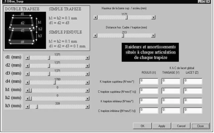
The parameters modification is performed thanks to a convivial interface including 4 dialog boxes. Fig. 5 gives as an example the dialog box aimed to modify the suspension parameters. The three other boxes concern the central part and the lateral parts of the boom and the contact points. The parameters can be manually modified and visualised.
Fig. 1. Example of a mounted sprayer with a trapezoïdal suspension : (a) General view
(b) Suspension (1), tank (2) and central boom part (3) (c) Boom suspension (d) vertical boom hinge
boom parts boom suspension (a) (d) (c) (b) (1) (2) (3)
Fig. 2. General multibody model (a) Suspension (b) whole model
8 VERTICAL HINGES BETWEEN 9 BOOM PARTS horizontal suspension (under construction)
vertical suspension (general case, double trapezium configuration)
contact planes (fixed to the boom, inside the contacts)
contact points (4 ahead, 4 rear) link fixed to the frame
box representing the sprayer frame
central part of the boom link fixed to the boom
first lateral part of the boom hinge
(a)
2.2. Modelling real machines
A trailed sprayer, with a 24 m boom length and a trapezoidal suspension, was modelled. It was equipped with an horizontal suspension (flexible blocks inserted at various locations between the boom and its suspension or frame).
1. Model adaptation
It is important to examine the machine to be modelled in detail and to identify all devices that should affect the dynamic behaviour of the boom. Sometimes a specific device is found that is not included in the model. In such a case, we
- do not take it into account and use the GMM, knowing that an error may affect the results; - try to simulate its effect by modifying another parameter in the GMM;
- modify the model to include the specific device.
In the present case, the modelled machine included three specific devices that greatly affected its horizontal behaviour. They are actually being included in the model.
2. Determination of the model parameters and construction of the specific model
(a) (b)
Fig. 4. Suspension hinges. (a) Main rotation axes (rolling) (b) Main (1) and secundary (2,3) rotation axes (with limited allowed movement).
(1) (2) (3) a b e c d f g h a,b e c d f g h a,c,e b,d,f g h a,b,c,d,e,f g h (a) (b) (d) (c)
Fig. 3. Most common boom suspensions. (a) double trapezium (undulating fields) (b) pendulum + trapezium (flat fields) (c) single trapezium (undulating fields) (d) single pendulum (flat fields)
Once the GMM is chosen (modified or not), the behaviour of a sprayer is entirely defined by its parameters. Once they are introduced in the GMM, the model becomes specific to that sprayer.
Direct measurements
All dimensions were easily obtained on the real machine. The masses and inertia of the boom parts were calculated using their dimensions and material properties (if available, a CAD model is very useful). The stiffness of the vertical hinges were measured comparing the angular displacement with the applied torque (Fig. 6). That was made using a dynamometer and a laser distance sensor (DME2000, Sick Optic Electronics). At the suspension level, the parameters could not easily be measured. The coefficients of friction were evaluated by testing the materials in the laboratory (Fig. 7). The acceleration of the sleigh gave an estimation of the cinematic coefficient of friction between the greased metal plate and the plastic runners. These were made of the same materials as the real contacts. To estimate the static coefficient, the mass (8) was gradually increased until the sleigh moves.
Adjustment - Undirect assessment
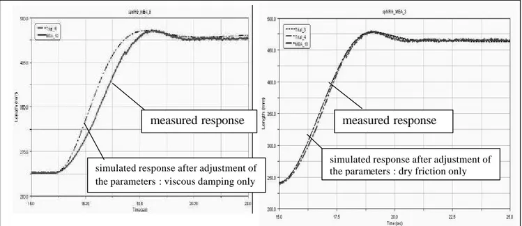
Some parameters could not be easily measured. However, by introducing their correct value in the model, the latter should reproduce the real behaviour of the sprayer. The boom behaviour was then measured in controlled conditions : in a laboratory, while the sprayer was motionless, release tests were made on the boom. The response of the boom (vertical movement after releasing) was measured using distance sensors. Then the same test was simulated using the modelling software. The effect of each parameter (stiffness, viscous damping coefficient, fr iction coefficient) on the response was identified. These parameters were then modified until the simulated response corresponded to the real response (Fig. 8). The friction coefficients were already measured (Fig. 7).
3. Validation of the specific model
The validation consisted in measuring the frame solicitations and the boom response simultaneously, preferably in real conditions. The frame movements were measured using a dynamic measurement unit (Crossbow Technology). This sensor measured the accelerations along three perpendicular axes and the rotation speeds about these axes. The responses were the horizontal or vertical movements of the boom or both. For the measurement of the horizontal movements, a measurement chain composed of 13 sensors was used. The signal treatment was based on sensor fusion and was fully described by Ooms et al. (2002). The horizontal speed of five points located along the boom was measured. The vertical movements of the boom were measured using 4 sensors and was also based on sensor fusion. The response measured in the field was compared to that of the specific model. If the difference is negligible, then the specific model is « ready to use ». If not, the difference should be judged depending on the further application.
3. Results
For validation of the model, the trailed sprayer machine was tested on a real meadow. The validation was successful for vertical movements (example is given in Fig. 9). That indicated that the model was suitable to predict efficiently the vertical movements of the boom as a response to the frame movements (pitch, yaw, roll, longitudinal, lateral and vertical motions).
Fig. 5. Example of dialog box : Geometry of the suspension and viscous damping
this part held fixed (3) distance sensor (1) applied force load cell or dynamometer (2)
TOP VIEW
(4) target of the distance sensor (5) hinge (3) (4) (7) to computer (5) Infrared distance sensor (4) Target for theinfrared sensor (3) Pulley (1)
Painted metal plate (6) Plastic runners (7)
sleigh (2)
Mass (8)
Displacement direction
Film of grease
Fig. 7. Devices used to evaluate the coefficients of friction at the contact points.
(8)
hinges.$-4. Conclusion
A general multibody model of a sprayer boom and its suspension was proposed. The model can be adapted to the specifications of most existing machines. The model and the associated methodology offer the potentiality to decrease the development costs of suspension and boom designs. The manufacturers who develop their sprayers with a 3D-CAD software should take more advantage of such a model.
5. References
Ooms, D., Lebeau F., Ruter R., Destain M.-F., 2002. Measurements of the horizontal sprayer boom movements by sensor data fusion. Computers and Electronics in Agriculture 33, 139-162.
Lebeau F., Bouchat X., Ruter R., Destain M.-F., 2002. Spray pattern simulation model for standardisation of boom behaviour tests. Aspects of Applied Biology 66, 427-434.
Fig. 9. Comparison of the vertical boom movements (at 8.5 m / centre) measured in the field and simulated using the multibody model. Trial at 6 km/h with a trailed sprayer.
measured response measured response
simulated response after adjustment of the parameters : viscous damping only
simulated response after adjustment of the parameters : dry friction only
Fig. 8. Adjustment of the parameters of the suspension for the second sprayer : the dry friction did better match than the viscous damping (X axis : time, Y axis : boom height at 1/4 length)