HAL Id: hal-00668760
https://hal.archives-ouvertes.fr/hal-00668760
Submitted on 10 Feb 2012
HAL is a multi-disciplinary open access
archive for the deposit and dissemination of
sci-entific research documents, whether they are
pub-lished or not. The documents may come from
teaching and research institutions in France or
abroad, or from public or private research centers.
L’archive ouverte pluridisciplinaire HAL, est
destinée au dépôt et à la diffusion de documents
scientifiques de niveau recherche, publiés ou non,
émanant des établissements d’enseignement et de
recherche français ou étrangers, des laboratoires
publics ou privés.
ARMS SWING EFFECTS ON A WALKING PLANAR
BIPED
Bassel Kaddar, Yannick Aoustin, Christine Chevallereau
To cite this version:
Bassel Kaddar, Yannick Aoustin, Christine Chevallereau. ARMS SWING EFFECTS ON A
WALK-ING PLANAR BIPED. ASME 2012 11th Biennial Conference on Engineering Systems Design and
Analysis - ESDA2012, Jul 2012, Nantes, France. �hal-00668760�
Proceedings of The ASME 2012 11th Biennial Conference On Engineering Systems Design And Analysis (ESDA2012) ASME /ESDA 2012 July 2-4, 2012, Ecole Centrale of Nantes, Nantes, France
ESDA2012-82561
DRAFT: ARMS SWING EFFECTS ON A WALKING PLANAR BIPED
Bassel KADDAR, Yannick AOUSTIN, Christine CHEVALLEREAU Institut de Recherche en Communications et Cyberntique de Nantes (IRCCyN)
(UMR CNRS 6597) Nantes, France 44300
Email: [email protected], [email protected] [email protected]
ABSTRACT
A walking gait is designed for a planar biped with two iden-tical three-link legs, a trunk and two one-link arms. This nine-link biped is controlled via eight torques to obtain a cyclic gait. The scope of this paper is to investigate the effects of arms swing on the reduction of energy consumption during walking of a fully actuated planar biped robot. Kinematics and dynamics of a biped, HYDROID, are used for this study. Desired gaits are con-sidered to be cyclic having single support phases separated by flat foot impacts. Different evolutions of arms: arms held, arms bound and arms swing will be compared. For each case, we use a parametric optimization method with constraints to produce ref-erence cyclic trajectories according to an energy criterion. The numerical results show that this criterion is lower in the case where arms swing.
1 INTRODUCTION
Several studies were done on the definition of walking gaits [1, 2]. Many researchers have attempted to achieve trajectories of walking using optimization. Roussel et al. have proposed a method, which considers the torques samples for a step as op-timization variables to generate trajectories by minimizing an energetic function [3]. Chevallereau et al. have used polyno-mials of fourth degree in order to set the movement in the joint space, and parametric optimization was achieved by minimizing a torques or an energy criterion by a sequential quadratic pro-gramming [4]. An optimal control has been implemented in [5]
using Pontryagin Maximum Principle (PMP) for the generation of a walking gait of planar biped.
Bipedal robots gaits have been widely studied, but the effects of arms on their walking gaits are not completely understood. Few studies and results are available to describe the effects of arms on walking gaits of a biped especially on the energy con-sumption. Aoustin and Formal’skii studied the optimal swing-ing of the biped’s arms of a ballistic walkswing-ing gait for a planar biped [6]. They showed that for a given period of the walking gait step and a length of the step, there is an optimal swinging amplitude of arms. For this optimal motion of the arms, the cost functional is minimum. However, the role of arms has been con-sidered to smooth walking and to increase its robustness as in [7]. The results show that the robot’s walking would be more stable and faster than walking without considering the role of arms [7]. Several approaches of upper body motion generation have been used to compensate the yaw moment during the motion, aiming at improving the motion stability of the robot [8]. The effects of angular momentum on the whole body motion have been stud-ied, namely a method of Resolve Momentum Control has been proposed for the planning of a walking humanoid robot [9].
Many experimental measurements on humans show that nor-mal arm swinging requires a mininor-mal shoulder torque, while holding the arms requires more torque in the shoulder and greater metabolic energy [10, 11]. For others, the main function of the arms while walking is to reduce fluctuations in the angular mo-mentum of the biped around the vertical axis. Arm swing reduces the metabolic cost of gait in both young and elderly adults in
con-x q2 0 q y (x , y ) h h
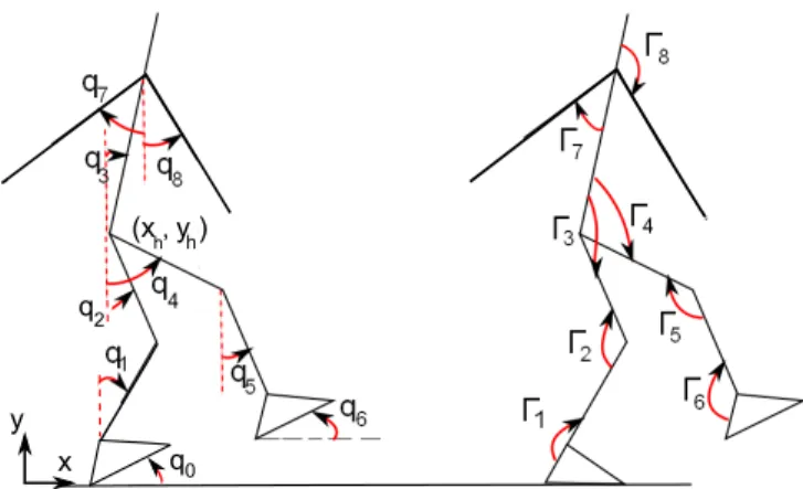
FIGURE 1. Planar biped generalized coordinates representation and
applied torques.
tributing probably to the stability [12]. Other researchers have interested in the coordination patterns of the elevation angles of the lower and upper limbs segments during locomotion [13].
Our goal is to compare different types of arms motion by means of a criterion related to the energy for a fully actuated biped robot where trajectories will not be ballistic.
We test three modes of evolution of the arms, as those used in the works [10, 11]: Arms bound where a single rigid body is used to model the trunk and arms, arms held mode in which the arms are almost held at their sides, and normal arms swing where arms swing freely in amplitude about the trunk. Therefore, we use two different models of our robot: a seven-link biped and a nine-link biped. Only the cyclic phases of walking are addressed in this study, the start-up and shutdown are not considered.
The paper is structured as follows: The studied robot is pre-sented in section 2. The dynamic model of the robot is illus-trated in section 3. In section 4, trajectories of cyclic motion are defined. The optimization strategy is explained in section 5. The results of gait trajectory optimization in the different cases of arms motion are shown and arms swing effects is discussed in section 6. Section 7 presents our conclusion and perspectives.
2 PRESENTATION OF THE ROBOT
Our nine-link bipedal robot presented in figure 1, is a pla-nar biped composed of two identical legs, two identical one-link arms and a torso. Each leg consists of a femur, a tibia and a rigid foot. Our model is derived from humanoid robot HY-DROiD [14], which is based on HANAVAN model of human body. Table 1 gathers the physical parameters of the biped, which is depicted in figure 1.
It is considered that all joints actuators are revolute, mass-less and frictionmass-less and can only move in the sagittal plane, and that torque discontinuities are allowed.
We focus on the generation of a planar biped walking cyclic
TABLE 1. PHYSICAL PARAMETERS OF THE ROBOT.
Description Mass Length Gravity Center Inertia Kg (m) (m) Kg.m2 Foot 0.678 Lp=0.2070 spx= 0.0135 0.00175 hp=0.06425 spy= 0.0321 tibia 2.188 0.392 0.1685 0.0276 Femur 5.025 0.392 0.1685 0.0664 Trunk 24.97 0.5428 0.2013 0.6848 Arm 2.15 0.586 0.2418 0.0578
gait. The walking step starts with a single support phase and ends with an instantaneous impact of the swing foot on the ground where the feet exchange their role, i.e. the stance foot becomes the swing foot and vice versa. In the next section, we will see the different models corresponding to different phases of walking.
3 MODEL OF THE ROBOT BIPED
Our dynamic modeling is based on the assumption of flat foot contact with ground, i.e. the support foot doesn’t rotate dur-ing the swdur-ing phase and the swdur-ing foot touches the ground with a flat contact.
3.1 DYNAMIC MODEL IN SINGLE SUPPORT
The generalized coordinates of the biped in single sup-port phase are described by the vector of absolute angles q = [q1q2...qn]t. This representation is shown in figure 1. Γ = [Γ1Γ2....Γn]t is the joint torque vector and Rj= [RxRy]t con-tains the horizontal and vertical components of the ground reac-tions on foot j. Where n depends on the biped model; n = 6 for the seven-link biped et n = 8 for the nine-link biped.
In simple support phase, the dynamic model is:
A(q) ¨q + C(q, ˙q) ˙q + G(q) = BΓ (1) where A(q) ∈ Rn×n is a positive definitive inertia matrix, C(q, ˙q) ∈ Rn×n contains the Coriolis and centrifugal forces, G(q) ∈ Rn×1is the vector of gravity forces and B ∈ Rn×nis the actuation matrix.
The dynamic model, presented in equation (1), is valid only if the stance foot remains fixed on the ground, i.e. there is no take-off, no sliding and no rotation during the single support phase. As a result, the stance foot is considered the biped’s base during this phase. The ground reaction forces acting on the stance foot R1during the single support phase can be calculated
· R1x R1y ¸ = m · ¨xg ¨yg ¸ + m · 0 g ¸ (2)
where m is the robot’s mass, xgand yg are the horizontal and vertical components of the biped’s center of mass, R1x and R1y
are the horizontal and vertical components of the ground reaction force on the stance foot.
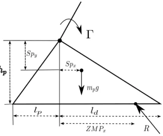
FIGURE 2. Balance of the stance foot.
According to figure 2, the Zero Moment Point (ZMP) can be calculated from the following equation:
ZMPx=Γ1+ SpxmRpg − hpR1x
1y (3)
The foot remains in contact with a flat foot only if the ZMP point remains strictly within the convex hull in the support area of the foot [15].
3.2 DYNAMIC MODEL IN INSTANTANEOUS DOUBLE SUPPORT
We denote Xh= [xh, yh] the position of the hip and q0 the
angle between the support foot and the ground. The position and configurations of the biped will be defined by the vector X = [q0; q; xh; yh].
The dynamic model in double support phase can be written to take into account the reaction forces applied by ground on the robot. The dynamic model in double support is expressed as:
Ae(X) ¨X + Ce(X, ˙X) ˙X + Ge(X) = BeΓ + Jet1Re1+ Jet2Re2 (4)
where Ae(X) is the positive definitive inertia matrix,
Ce(X, ˙X) represents the vector of coriolis and centrifugal forces,
Ge(X) contains the gravity forces, Je1and Je2 are the jacobian
matrices of feet and Re1∈ R3×1and Re1∈ R3×1are the vectors
of ground reaction forces and moment on the two feet.
Generally speaking, two results are possible after the impact, if we assume that there is no slipping of the leg tips. The stance leg lifts off the ground or both legs remain on the ground. In the first case, the vertical component of the velocity of the taking-off leg tip and the ground reaction in the stance leg just after the impact have to be directed upwards [6]. The ground reaction in the taking-off leg tip must be null. In the following, we have considered only the first case because that for the second case trajectories require more energy.
The support foot will immediately leave the ground after having impact on swing foot. Therefore, Re1= 0. The impact
model is deduced from the dynamic model in double support (4) by assuming that the reaction force in the new support foot is are Dirac delta-functions. The impact model is:
Ae(X)( ˙X+− ˙X−) = Jet2I2 (5)
Where ˙X−and ˙X+are the vector of links velocities just
be-fore and just after impact respectively. The vector I2∈ R3×1
rep-resents here the ground reaction forces and moment on the sup-port foot at the time of impact. The velocities of the new supsup-port foot tips after impact are zeros and this constraint is expressed as:
Je2X˙+= 0 (6)
The equations (5) and (6) are simultaneously solved to find the velocities vector ˙X+just after impact and the impact impul-sive forces and moment vector I2∈ R3×1.
· Ae −Jet2 Je2 03×3 ¸ · ˙ X+ I2 ¸ = · AeX˙− 03×1 ¸ (7) The above system of equations is based on the following hypoth-esis:
2. The swing leg hits the ground with flat foot and the support leg immediately leaves the ground.
3. The robot configuration is constant during the impact. 4. The velocities, accelerations and torques are discontinuous
at impact.
4 DIFINITION OF MOTION OF WALKING GAIT
We are interested in cyclic walking motion which means that all walking steps are symmetrical. Each step is associated with a swing of one of the two feet. The walking motion consists of alternating phases of single support and impacts. The swing leg after the impact becomes the stance leg for the next step.
In order to generate a reference trajectory for one walking step, polynomial functions in time of four order qi(t) are used to define the evolution of generalized variables q. These polyno-mial functions ensure that the jerk of the joint’s motion is contin-uous. To determine the coefficients of equation (8), five boundary conditions are needed which are the initial joint configurations qini, velocities ˙qiniat time zero, the intermediate configurations qintat time T /2, the final joint configurations q−, and velocities ˙q−at time T . The reference polynomial function is represented below:
qi(t) = a0+ a1t + a2t2+ a3t3+ a4t4 for i=1 to n (8)
Once we calculate the coefficients of the polynomial func-tion, we can calculate the generalized coordinates q and veloci-ties ˙q and acceleration ¨q of joints at any moment. Then, joints torques can be calculated from equation (1) and the ground reac-tion can be determined from equareac-tion (2).
By taking into account the exchange of the role of legs be-tween the final time (t = T) for one step and the initial time (t = 0) of the next step such that the stance leg after the contact with ground becomes a swing leg, initial joint configurations and velocities qini, ˙qinirespectively are deduced from joint configura-tions and velocities just after the impact q+, ˙q+respectively.
qini= Eq+, ˙qini= E ˙q+ (9) where E ∈ Rn×nis the permutation matrix.
5 TRAJECTORY OPTIMIZATION
In the parametric optimization problem, reference trajectory for a walking step of biped is generated and then optimized to minimize a criterion under constraints. Matlab fmincon function is used to optimize the reference trajectory. This Matlab function allows us to optimize an objective function under nonlinear and linear constraints.
5.1 THE OPTIMIZATION CRITERION
The minimized criterion Cqis a criterion related to the enrgy. This criterion is used to optimize the trajectory over the distance d for a motion on a duration of one step T .
Cq=1 d
Z T 0 Γ
tΓdt (10)
The robot parameters to optimize are presented in the fol-lowing section.
5.2 THE OPTIMIZATION VARIABLES
From the fact that the walking gait is cyclic and composed of single support phases and impacts the number of optimization variables can be reduced as follows. The optimization variables for the nine-link biped are:
- 1 parameter of step length d. During optimization proce-dure, we impose that the walking speed V is fixed. then, the step duration T is calculated from T = d/V .
- 5 parameters of final configurations just before the impact (hip configurations xh, yhand trunk angle q3and 2
parame-ters of arms configurations). From the position of hip, The final generalized vector q−is calculated using the Inverse Geometric Model (IGM). Since we are considering cyclic step and the exchange of the role of legs, the initial configu-rations qinican be deduced from final configurations q−. - 8 parameters of final velocities just before impact. Initial velocities ˙qini can also be determined from final velocities
˙q−.
- 8 parameters of intermediate configurations qint of the robot.
For our parametric optimization problem, we have 3n − 2 = 22 parameters to optimize for the nine-link biped robot which allow to calculate all the coefficients of polynomial functions and thus to generate the biped trajectories for one walking step. We also have 3 × 6 − 2 = 16 optimization parameters for the seven-link biped.
The constraints are defined in the following section. 5.3 THE OPTIMIZATION CONSTRAINTS
To ensure that the biped will successfully walk and that the trajectory is possible, a number of constraints must be satisfied. Two types of constraints are used to ensure walking on level ground.
1. Basic Constraints during the single support phase and the impact:
The condition of no-take-off must be satisfied in single sup-port phase, i.e. the vertical component of reaction force on
stance foot must always be positive so that the biped foot stay on the ground.
R1y> 0, I2y> 0 (11)
The condition of no slipping must be satisfied. In supposing the suitable value of the coefficient of friction µ, the con-straint is mathematically written as:
µR1y≥ |R1x|, µI2y≥ |I2x| (12)
The Zero Moment Point (ZMP) of the biped’s stance foot must be within the interior of the support polygon, Fig. 2.
−lp< ZMPx< ld (13) Supplementary constraints at the impact: The heel and toe velocities of the foot leaving the ground just after impact must be positive to ensure the take-off.
½
Vheel≥ 0
Vtoe≥ 0 (14)
The swing foot must not touch the ground during the single support phase i.e. the distance of swing foot heel and toe must be positive.
½
yheel> 0
ytoe> 0 (15)
where yheel and ytoe are the vertical distances of swing foot heel and toe respectively during the swinging phase. 2. Technological Constraints: These constraints consist of
physical limitations of the biped’s actuators and articula-tions. The constraints on joints position, velocity and torque are:
Each actuator can produce limited maximum torque such that
|Γi| − Γi,max≤ 0, for i = 1, ..., n (16) Where Γi,maxdenotes the maximum value of torque for each actuator.
Each actuator can produce limited maximum velocity such that
| ˙qi| − ˙qi,max≤ 0, for i = 1, ..., 6 (17) where ˙qi,max represents the maximum value of velocity for each actuator.
The upper and lower bounds of joints for the configurations during the motion are:
qi,min≤ qi≤ qi,max, for i = 1, ..., 6 (18) where qi,minand qi,maxare the minimum and maximum joint configuration limits respectively. We chose in the first time not to constrain the arms joints.
6 RESULTS
The robot trajectories are optimized and the optimization criterion of walking is calculated for the following cases:
A. Normal Arms Swing, which is obtained by optimization of the nine-link biped.
B. Arms Held, where the arms are almost held to the trunk during the motion. The goal is to move the actuated arms such that they can be considered as connected to the torso. Joint velocities and the joint variables of arms can not be imposed continuously equal to those of trunk during a step due to the discontinuity in the impact. Therefore, relative joint velocities and joint variables (arms, trunk) are zeroed only just before impact. This can be expressed as follows:
qj−− q3−= 0 , ˙qj−− ˙q3−= 0; j = 7, 8 (19)
The angular velocities of the arms joints just after impact will still remarkably different from those of the trunk joint just after impact. Consequently, we will not obtain the same evolution of the arms angles as the trunk angle during the sigle support phase. Therefore, we constrained the research of optimal solutions in order to find trajectories in such way that arms velocities will not be very different from trunk velocities just after the impact. We used the following con-straints:
˙
qj+− ˙q3+≥ε (20)
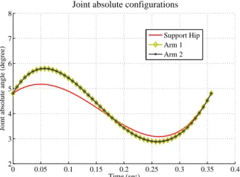
0 0.05 0.1 0.15 0.2 0.25 0.3 0.35 0.4 2 3 4 5 6 7 8 Time (sec)
Joint absolute angle (degree)
Joint absolute configurations
Support Hip Arm 1 Arm 2
FIGURE 3. Orientations of the held arms q7, q8and the trunk q3
ver-sus time at walking speed V = 0.8 m/s.
By applying these constraints, arms velocities just after im-pact differ very slightly from those of the trunk. Conse-quently, the evolution of the arms will be more closer to this of the trunk than the case where these contraintes are not applied, figure 3.
C. Arms Bound where the arms are bound to the sides of the body. Here, the biped has six joints and the mass and inertia of the arms are integrated into the trunk.
By looking for the optimal solutions at several walking speeds and for different modes of evolution of the arms, we found different walking gaits.
NORMAL ARMS SWING MODE
For the obtained optimal gaits, arms swing with very big am-plitudes. To obtain gaits where arms swing normally, like that of human gait, we have to restrict the movement of the arms. Dif-ferent ways can be used to constrain the movement of arms, by putting constraints on the maximum velocities of the arms actua-tors, or by limiting the relative angles (arms, trunk) for example. We have defined the arms constraints as:
q7− q3≤θmax, q8− q3≤θmax (21)
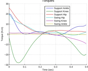
A walking gait of this type of motion is shown in figure 4 where the maximum values of relative angles (arms, trunk) are set to 60 degrees. The evolution of torques versus time for the previous trajectory is illustrated in figure 5.
−0.5 −0.4 −0.3 −0.2 −0.1 0 0.1 0.2 0.3 0.4 0.5 0 0.5 1 1.5 m m
FIGURE 4. Optimal trajectory at walking speed V = 0.8 m/s,θmax=
60o. 0 0.05 0.1 0.15 0.2 0.25 0.3 0.35 0.4 −15 −10 −5 0 5 10 15 20 Time (sec) Torques (N.m) Arms Swing Support Ankle Support Knee Support Hip Swing Hip Swing Knee Arm 1 Arm 2 Swing Ankle
FIGURE 5. Evolution of torques versus walking speed V =
0.8 m/s,θmax= 60o.
ARMS HELD MODE
The arms swing in small amplitudes with the trunk. Figure 6 shows the optimal walking gait obtained at a walking speed of 0.8 m/s. The evolution of torques versus time is illustrated in figure 7.
−0.5 −0.4 −0.3 −0.2 −0.1 0 0.1 0.2 0.3 0.4 0.5 0 0.5 1 1.5 m m
FIGURE 6. Trajectory with arms held at walking speed of V =
0.8 m/s. 0 0.05 0.1 0.15 0.2 0.25 0.3 0.35 0.4 −20 −15 −10 −5 0 5 10 15 20 Time (sec) Torques (N.m) Arms Held Support Ankle Support Knee Support Hip Swing Hip Swing Knee Arm 1 Arm 2 Swing Ankle
FIGURE 7. Evolution of torques versus walking speed V = 0.8 m/s.
ARMS BOUND MODE
Figure 8 shows the optimal walking gait obtained at a walk-ing speed of 0.8 m/s. The evolution of torques versus time is illustrated in figure 9.
DISCUSION OF RESULTS
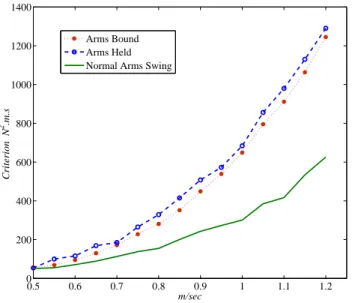
Once the optimal solutions for different types of arms mo-tion at several walking speeds are obtained and the values of the energy criterion are calculated, we plot the values of en-ergy criterion in function of walking speed, figure 10. The solid
−0.4 −0.2 0 0.2 0.4 0.6 −0.2 0 0.2 0.4 0.6 0.8 1 1.2 1.4 Step Length (m) Robot Height (m)
FIGURE 8. Trajectory with arms bound at walking speed of V =
0.8 m/s. 0 0.1 0.2 0.3 0.4 0.5 −30 −20 −10 0 10 20 30 Time (sec) Torque (N.m) Torques Support Ankle Support Knee Support Hip Swing Hip Swing Knee Swing Ankle
FIGURE 9. Evolution of torques versus walking speed V = 0.8 m/s.
curve represents the criterion as function of time for the nine-link biped with θmax = 60o. For higher walking speeds more than V = 0.5 m/s, optimal trajectories with the arms swing seems to be more interesting in terms of the optimization criterion than optimal ones for the seven-link biped (arms bound model). For the nine-link biped, it is always more interesting to swing the arms, while the trajectories are more expensive if the arms are held. These results seem very similar to those of experiences on humain presented in the study of [10] .
0.5 0.6 0.7 0.8 0.9 1 1.1 1.2 0 200 400 600 800 1000 1200 1400 m/sec Criterion N 2 .m.s Arms Bound Arms Held Normal Arms Swing
FIGURE 10. Evolution of the criterion related to the energy versus
walking speed. 0.5 0.6 0.7 0.8 0.9 1 1.1 1.2 1.3 0 500 1000 1500
Criterion of the whole biped
Criterion m/s 0.5 0.6 0.7 0.8 0.9 1 1.1 1.2 1.3 0 5 10 15 20 25 Walking speed
Criterion repartition in the arms
N
2.m.sec
Normal Arms Swing Arms Held
Normal Arms Swing Arms Held
FIGURE 11. Criterion repartition in the arms versus walking speed.
For the two cases: normal arms swing and arms held mode, we recalculated the same criterion, but by considering only the torques applied to the arms (in the shoulders). Figure 11 shows that arms swinging is not a passive movement for the obtained optimal walking gaits composed of single support phases and impacts. Therefore, it is necessary to actuate the joints of the shoulders to get the optimal movement with arms swing. For
higher walking speeds, the maximum torques in the shoulders are higher when the arms swing, figure 11. The lower cost functional in the case of arms swing can be explained by that more torques applied to the arms joints leads to less important torques in the other joints of the biped especially in the support leg (figure 5 and figure 7). For the arms held mode, the criterion repartition in arms seems to be almost constant versus walking speed. This repartition is used to keep arms held to the trunk and that is why such trajectories require higher criterion than bound arms model.
7 CONCLUSION AND PERSPECTIVES
Optimal walking gaits with arms swing were found. To ob-tain a good look arms swing, arms motion should be limited. For high walking speeds and when the arms swing, the selected en-ergy criterion of the biped is lower the cases where there is no arms or arms are held. We found that the optimal movement of arms swing is not a passive one and that the actuation of the arms reduces the torques needed in the actuators of on the biped other joints and therefore less value of energy criterion will be re-quired. This work will be extended to 3D bipedal robots. Other types of walking gaits will also be explored.
ACKNOWLEDGMENT
Thanks go to Tishreen University and to the Ministry of High Education in Syria for their support.
REFERENCES
[1] Mu, X., and Wu, Q., 2006. “A complete dynamic model of five-link bipedal walking”. American Control Conference, 2003. Proceedings of the 2003, 6, pp. 4926–4931. [2] Tlalolini, D., Aoustin, Y., and Chevallereau, C., 2010.
“De-sign of a walking cyclic gait with single support phases and impacts for the locomotor system of a thirteen-link 3d biped using the parametric optimization”. Multibody System Dy-namics, 23, pp. 33–56.
[3] Roussel, L., Canudas-De-Wit, C., and Goswami, A., 1998. “Generation of energy optimal complete gait cycles for biped robots”. International Conference on Robotics and Automation, 3, pp. 2036–2041.
[4] Chevallereau, C., and Aoustin, Y., 2001. “Optimal refer-ence trajectories for walking and running of a biped robot”. Robotica, 19, pp. 557–569.
[5] Bessonnet, G., Chessé, S., and Sardain, P., 2004. “Optimal gait synthesis of a seven-link planar biped”. The Int. J. of Robotics Research, 33, pp. 1059–1073.
[6] Aoustin, Y., and Formal’skii, A., 2008. “On optimal swing-ing of the biped arms”. International Conference on Intel-ligent Robots, IROS 2008., 3, pp. 2922–2927.
[7] Shafii, N., Khorsandian, A., Abdolmaleki, A., and Jozi, B., 2009. “An optimized gait generator based on fourier series towards fast and robust biped locomotion involving arms swing”. International Conference on Automation and Lo-gistics, ICAL2009, pp. 2018–2023.
[8] Xing, D., and Su, J., 2010. “Arm/trunk motion generation for humanoid robot”. SCIENCE CHINA Information Sci-ences, 53, pp. 1603–1612.
[9] Kajita, S., Kanehiro, F., Kaneko, K., Fujiwara, K., Harada, K., Yokoi, K., and Hirukawa, H., 2003. “Resolved momen-tum control: humanoid motion planning based on the lin-ear and angular momentum”. International Conference on Intelligent Robots and Systems, IROS 2003, 2, pp. 1644– 1650.
[10] Collins, S., Adamczyk, P. G., and Kuo, A., 2009. “Dynamic arm swinging in human walking”. Proceedings of the Royal Society B: Biological Sciences, 276, pp. 3679–3688. [11] Collins, S., 2008. “Dynamic walking principles applied to
human gait”. PhD thesis, University of Michigan.
[12] Ortega, J. D., Fehlman, L. A., and Farley, C., 2008. “Effects of aging and arm swing on the metabolic cost of stability in human walking”. Journal of Biomechanics, 41, pp. 3303– 3308.
[13] Barliya, A., Omlor, L., Giese, M., and Flash, T., 2009. “An analytical formulation of the law of intersegmental coor-dination during human locomotion”. Experimental Brain Research, 193, pp. 371–385.
[14] Alfayad, S., 2009. “Robot humanoïde hydroïd : Action-nement, structure cinématique et stratégie de contrôle”. PhD thesis, University Versailles Saint Quentin, Paris. [15] Kajita, S., Hirukawa, H., Harada, K., and Yokoi, K.,
2009. Introduction à la commande des robots humanoïdes. Springer.