HAL Id: hal-00354364
https://hal.archives-ouvertes.fr/hal-00354364
Submitted on 3 Jul 2017
HAL is a multi-disciplinary open access
archive for the deposit and dissemination of
sci-entific research documents, whether they are
pub-lished or not. The documents may come from
teaching and research institutions in France or
abroad, or from public or private research centers.
L’archive ouverte pluridisciplinaire HAL, est
destinée au dépôt et à la diffusion de documents
scientifiques de niveau recherche, publiés ou non,
émanant des établissements d’enseignement et de
recherche français ou étrangers, des laboratoires
publics ou privés.
Public Domain
Experimental characterization of the self-healing of
cracks in an ultra high performance cementitious
material
Sébastien Granger, Ahmed Loukili, Gilles Pijaudier-Cabot, Gilles Chanvillard
To cite this version:
Sébastien Granger, Ahmed Loukili, Gilles Pijaudier-Cabot, Gilles Chanvillard. Experimental
charac-terization of the self-healing of cracks in an ultra high performance cementitious material: Mechanical
tests and acoustic emission analysis. Cement and Concrete Research, Elsevier, 2007, 37 (4),
pp.519-527. �10.1016/j.cemconres.2006.12.005�. �hal-00354364�
Experimental characterization of the self-healing of cracks in an ultra high
performance cementitious material: Mechanical tests and
acoustic emission analysis
S.
Granger
a,
A. Loukili
a,
G. Pijaudier-Cabot
a,
G. Chanvillard
ba
R&DO— Institut de Recherche en Génie Civil et Mécanique (GeM), UMR CNRS 6183, Ecole Centrale de Nantes — 1 rue de la Noë, BP 92101, 44321 Nantes Cedex 3— France
b
Lafarge Research Centre— 95 rue du Montmurier, 38290 St Quentin Fallavier — France
Self-healing of cracks in an ultra high performance concrete, considered as a model material, is investigated in this paper. An experimental program is carried out in order to quantify the phenomenon, which has been mainly highlighted by means of water permeability tests until now. Mechanical behaviour of self-healed concrete under three points bending, and acoustic emission analysis of the cracking mechanisms are reported. The mechanical tests demonstrate a recovery of the global stiffness, depending on the time of healing, for specimens initially cracked and then self-healed, and a slow improvement of structural strength. The acoustic emission (AE) analysis is performed in order to show that the mechanical response is due to new crystals precipitating in the crack. The microcracking of these products during three points bending tests is highlighted and an energy analysis provides insights about the cracking process of healed concrete, including damage of the newly formed crystals and continuation of the crack propagation.
Keywords: Self-healing; Microcracking; High performance concrete; Mechanical properties; Acoustic emission
1. Introduction
For many concrete structures in the course of their lifetime, the assessment of durability is a key parameter needed in order to know whether safety is ensured or not. The presence of cracks, due to mechanical stresses or time dependent effects (shrinkage, creep…) is one of the major factors which can influence durability and serviceability of concrete structures in terms of resistance, permeability and transfer properties.
Self-healing of cracks is one phenomenon acting positively in durability problems of concrete. This process can take place only in presence of water (dissolved CO2is not always needed),
and consists of chemical reactions of compounds exposed at the cracked surfaces. These reactions produce crystals, and the accretion of these from the opposite surfaces of a crack can
re-establish the continuity of the material eventually. The essential requirement, with water, is the presence of compounds capable of further reaction. Thus, cement, hydrated or not, is the essential reactive element. There are two major assumptions regarding the reactions of healing [1]: the hydration of unhydrated clinker available in the microstructure of hardened concrete (important for concrete with low water/cement ratio), or the precipitation of calcium carbonate CaCO3. The first
hypothesis requires only the presence of water, and the second one the presence of dissolved CO2in addition. Silting up of
cracks or deposition of debris can contribute to healing but can not provide it by themselves[2].
Most studies carried out until now highlight the self-healing phenomenon by means of water permeability tests. A diminution of the flow rate through cracked concrete is the main technique used to characterize self-healing of cracks. Edvardsen [2] performed such tests, conducted on small concrete specimens, with a single tensile crack in each. The
typical results demonstrate that leakage of water through the specimen quickly drops to a reduced level. These results show the reaction of compounds on the crack surface, followed by diffusion through the newly formed crystals. Edvardsen explains the phenomenon by the crystallization of calcium carbonate CaCO3, as the main element. Hearn[3,4]carried out
also permeability tests on mortar (with 78% of hydrated clinker), and water cured concrete with insignificant amount of unhydrated clinker. The author investigates the chemical effects, like continuing hydration, dissolution and deposition of soluble species. Chemical analysis of water, inflow and outflow, points out a significant increase in Ca2+ ions concentration in outflow, which indicates a phenomenon of dissolution–deposition, especially of calcium carbonate CaCO3. These experiments show that the phenomenon is of
particular importance for water tightness and transfer properties of concrete structures. Another kind of experiments was performed by Jacobsen and Sellevold [5] to highlight self-healing of cracks. It consists in damaging concrete cubes by rapid freeze/thaw cycles, and then storing them in water. Deterioration and healing are measured through the evolutions of the compressive strength and the resonance frequencies giving the dynamic modulus of elasticity. Freeze/thaw cycles lead to a decrease of both resonance frequencies and compressive strengths, and self-healing gives a substantial recovery of the frequency but only a small recovery of the compressive strength. The author explains this small recovery by the fact that cracks are not fully filled with the newly formed crystals. SEM observations[6]confirm that and show that most of the crystals seen in the cracks are newly formed C–S–H.
Very little tests have been performed in order to investigate the role of self-healing on mechanical properties. In addition to Jacobsen's experiments, data from Pimienta and Chanvillard[7]
presents some mechanical results of concrete specimens damaged under three points bending and then healed, and point out a resonance frequency recovery especially. Ter Heide
[8]also provides some mechanical results on the behaviour of cracked concrete at early age. The present contribution aims at providing additional insights about the mechanical behaviour of self-healed concrete specimens. An experimental program is carried out on an ultra high performance concrete, considered as a model material, with a low water to cement ratio. The tests include cracking of prismatic specimens, and mechanical characterization after ageing, by means of three points bending tests. The mechanical behaviour of healed concrete specimens for several periods of ageing is presented. Acoustic emission analysis is also performed with the aim of providing some additional, qualitative, information on the microcracking process of healed specimens.
2. Experimental program 2.1. Concrete specimens
The experimental program is performed on an ultra high performance cementitious material– UHPC– with W/C ratio close to 0.2: this induces a large amount of unhydrated cement
(50 to 60%) [9], which can contribute to self-healing considering the hypothesis of hydration of anhydrous clinker, as one part of the self-healing mechanism. This concrete is considered as a model material for the experimental program because the quantity of potential reactive compounds upon cracking is very high. The influence of the mix design on the phenomenon is not considered. The composition of this UHPC includes cement, silica fume, sand (maximum aggregate size 2 mm) water and superplasticizer. It is mixed with a conventional industrial mixer, and its rheology is between fluid and self-compacting. In order to have a localized crack during the mechanical tests, a notch of depth 20 mm and thickness 1.5 mm is performed in each specimen by placing a PMMA plate at the midpoint perpendicular to the long direction of the mould. After casting, specimens (dimensions of 50 × 100 × 500 mm3) are cured for 2 days at 20 °C and 100% relative humidity. A thermal treatment is then applied, so as to accelerate hydration and activate the pozzolanic reaction. The specimens are placed in a climate chamber with a controlled environment of 90 °C and 100% relative humidity during 48 h. With this treatment, the material is stable and exhibits very little creep and shrinkage[10,11].
2.2. Mechanical test configuration
The principle of the mechanical tests is to perform a preliminary phase aimed at cracking the prismatic notched specimens, followed by ageing, enabling self-healing or not, and then by the mechanical characterization of these aged specimens.
The specimens are loaded under three points bending. The tests are notch opening controlled with a constant rate of 0.05μm/s. The crack mouth opening displacement (CMOD) is measured (Fig. 1), with a sensor placed between two steel plates stuck on each side of the notch on the bottom face of the specimen. The aim of this preliminary phase is to get a controlled cracking of the specimen. The objective of the study is to quantify the mechanical behaviour of healed concrete specimens, so, it was decided to aim a single residual crack width of approximately 10μm, which permits to get a fast self-healing. It is worth noting that the influence of the crack width
[4,12]on the phenomenon is not investigated here. Pre-cracking is performed in the post peak regime: after having reached the peak load (comprised between 3 and 4 kN), unloading is performed when the applied force reaches 2 kN, which
represents approximately 60% of the peak load. This unloading is also notch opening controlled with the same rate as loading. Residual crack mouth opening displacements for specimens after unloading range between 8μm and 15 μm.
After this first step, the specimens are stored in specific conditions for ageing. Five different ageing periods have been selected: 1, 3, 6, 10 and 20 weeks. There are two kinds of ageing: for each period, 3 cracked specimens have been stored in water, and 3 others in air. Specimens aged in water have been totally immerged in tap water at 20 °C, with nor movement, neither renewal. Specimens aged in air have been stored at 20 °C and 50% relative humidity. After each period of ageing, the last step of the experimental program consists in reloading the specimens under three points bending, in order to characterize their residual mechanical behaviour. Tests are also notch opening controlled and are conducted until total failure two hours after having stopped the ageing conditions. 2.3. Acoustic emission analysis
Acoustic emission (AE) is a microseismic (elastic) wave generated from dislocations, microcracking and other irrevers-ible changes in a stressed material. The transmitted waves are detected by transducers on the surface of a specimen. Aside from applications in geophysics and in geotechnical engineer-ing[13], AE technique has been mainly developed to monitor and inspect structures because an increase of acoustic activity is generally a very sensitive precursor to failure of structural components (see e.g. Ref. [14]). For concrete structures, this property has been highlighted initially by Rusch in 1960[15]. In more recent works on concrete fracture such as those by Landis
[16], or Chen and Liu [17] among others, the correlation between cracking and the cumulated number of acoustic event is clearly exhibited. It is further possible to analyse in more details the acoustic wave in order to obtain a more accurate information on its cause: mode I crack opening, mode II, friction…, using moment tensor analysis of the acoustic wave
[18]or frequency analysis[19].
AE analysis can provide also valuable information on the acoustic source location and thus on the process of cracking in concrete (such procedures have been devised to locate earth-quakes long ago). AE source location is used to investigate the shape and extend of the fracture process zone, and some correlation with the mechanical response of specimens (see e.g. Refs.[16,17,20–23]). Source localisation is based on the arrival times of P-waves, recorded by several transducers (generally 4 in a 2D analysis, and 6 to 8 in 3D analyses). Arrival times are either obtained manually, or automatically. Fixed or floating threshold techniques are the most common but there exist also some more refined and robust methods, e.g. relying in addition on the rising time of the signal, or on more refined, e.g. autoregressive algorithms [24]. In 2D and 3D localisation schemes, the unknowns of the problem are the source location and the origin time at which the event is generated. In order to obtain some information about the accuracy of the event localisation algorithm, the problem needs to be over-deter-mined. Classically, in a 2D analysis there are three unknown:
the time at which the event originated and the two coordinates of the event location. Three sensors provide a unique solution. When more than 3 sensors are used, redundancy of experimen-tal data may yield the most probable location of each event, and thus an estimate of the error of the source location technique may be obtained. For a recent discussion of the accuracy of AE localisation technique in the complex context of pre-stressed reinforced concrete analysis, see Ref.[25].
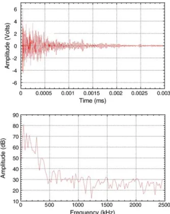
In the present study, all the specimens are instrumented with an AE system, during the pre-cracking and reloading phases. The instrumentation consists of four piezoelectric transducers, with a band characteristic (50–200 kHz) and resonant frequency 150 kHz, placed in a rectangular array just above the notch of the specimens, in order to cover the expected zone of the process zone. The dimension of the rectangular array is 140 × 65 mm2. The transducers are placed on one side of the specimen, and coupled to the material with silicon glue.Fig. 2
shows the wave form and Fourier transform of a typical acoustic event whose measured frequency content, above what can be considered as a noise recorded by the sensor, is below 400 kHz.
The detected signals are amplified with 40 dB gain amplifiers. The frequency range of the acquisition of wave forms is set from 20 kHz to 400 kHz. The signal detection value (in amplitude) is set to 5 dB over the background noise in order to overcome it. In the present case it was 35 dB. It is clear that the number of detected events is dependent on the value of this threshold. The lower it is, the larger the number of detected event (including very weak and possibly spurious ones). One should keep in mind, however, that the purpose of the present study is to compare data between healed and non-healed
Fig. 2. Typical waveform of an acoustic event (top), and corresponding Fourier transform (bottom).
specimens. Firstly, it is important to keep the same procedure for both types of specimen. Secondly, the amount of recorded event is already quite large and, as we will see further, we will filter out less energetic (weak) events. Energetic events are usually way above this threshold and should be detected independently from small variations of it. This is the reason why we could not see some significant effect of the value of the detection threshold when carrying out sensitivity analyses on recorded wave forms after testing. Note finally that the UHPC used for these experiments is rather homogeneous. There is a very little attenuation, which makes the AE analysis much easier to perform than for normal concrete structures.
A planar location algorithm, from the commercial software AEWin[14], is used for AE localisation. It is based on arrival time differences, the origin time corresponding to the first hit sensor for each located event (beside there is very little difference between the true origin time and this one in view of the close distance between recorded sources and the sensors). As explained above, onset time picking is performed with a fixed threshold technique. In this planar location technique, we have three unknowns (two coordinates and the origin time), and we use 4 sensors. The event location is obtained by minimi-sation according to standard Simplex search. Before the tests, the accuracy of the event location is evaluated. An event is generated, with a standard reproducible Hsu–Nielsen source (in practise a conventional pencil lead broken), at several positions on the surface of the specimen on which the transducers are placed, and the position calculated by the algorithm is compared to the true location of the event. For the ultra high performance concrete used in this study, the statistical accuracy of event
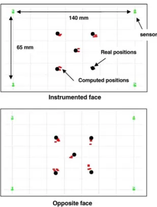
location (based on 20 simulations on 5 different places in the location area) is ± 3 mm as shown inFig. 3a. This is correct in comparison with the diameter of the transducers (15 mm). Note that this is the accuracy with respect to a standardised acoustic source, and not to real acoustic events due to microcracking. It is expected that the accuracy should deteriorate as the amplitude (or energy) of the events decreases and is not as strong as the standardised source. Again since weak events will be further filtered out, one may consider that the accuracy does not de-teriorate a lot in the present analysis.
Since we use a 2D planar localisation algorithm, it is important to determine the effect of the specimen thickness. In fact, this algorithm provides a projection of all the events onto a single plane. Hence the projection may generate a bias and some additional error in the localisation scheme. The same accuracy tests as above have been conducted on the opposite side of the specimens, which is not instrumented. Results are reported in
Fig. 3. We can observe that the accuracy (with respect to a standardised acoustic source) is about the same and does not depend on the face of the specimen on which the source is located. Therefore, we may conclude that the bias induced by the specimen thickness is within the accuracy of the localisation algorithm.
3. Mechanical characterization of the self-healing of cracks Three kinds of mechanical results are presented in Fig. 4. These are curves for a specimen pre-cracked and then immediately reloaded, and for specimens cracked and aged during 3 weeks (before reloading) respectively in water and in air. The objective of this figure is to show the effect of storage in water, and to compare with the storage in air and with the immediate reloading of the specimen. The curves display the applied load versus the crack mouth opening displacement. Each curve presents two parts: the pre-cracking phase, consisting in loading and unloading when the applied load reaches 2 kN in the post peak regime, and the reloading phase, immediate or after ageing. The reproducibility of the pre-cracking phase of the tests can be seen on this figure. It also shows that the cracked specimen immediately reloaded, and the
Fig. 3. Accuracy of the 2D planar localisation scheme measured with a Hsu– Nielsen source: a) source placed on the instrumented side of the beam; b) source placed on the back surface of the specimen.
Fig. 4. Mechanical behaviour of a specimen cracked and immediately reloaded, of a specimen cracked and aged 3 weeks in water before reloading, and of a specimen cracked and aged 3 weeks in air before reloading— pre-cracking and reloading phases.
specimen aged in air, have the same mechanical behaviour, which is the typical reloading after cracking. On the contrary, there is a difference with the mechanical behaviour for the specimen stored in water, on the reloading stiffness and the reloading peak load especially. This result confirms that water is needed for the self-healing phenomenon.
We now have to discuss the influence of the ageing time, which is, of course, an important parameter.Fig. 5presents the average reloading curves for three specimens stored in water and for three specimens stored in air, for the 5 different periods of ageing. For the sake of clarity, only the reloading parts of the total curves are presented. The CMOD at the beginning of the tests is set to 0, in order to have the same initial state, but in reality we should have the value of the residual CMOD at the end of the pre-cracking phase.
We can notice that specimens stored in air exhibit very similar mechanical behaviours for the 5 periods of ageing. It
Fig. 5. Mechanical reloading behaviour of aged specimens for different ageing times— comparison ageing in water and ageing in air; average curves: (a) 1 week, (b) 3 weeks, (c) 6 weeks, (d) 10 weeks, and (e) 20 weeks.
Fig. 6. Average mechanical behaviour of reference specimens (stored without crack in water for 10 weeks, and then cracked and immediately reloaded) and of cracked specimens stored in water for 10 weeks before reloading.
means that air has no influence on the mechanical properties of cracked specimens, even for a long period of ageing. After the usual hysteresis at the begining of reloading (until 0.3 kN), the reloading part corresponds to the re-opening of the existing crack until the peak load, followed by the continuation of the crack propagation. On the contrary, there is a clear evolution of the mechanical behaviour of specimens stored in water with the time of ageing. The reloading stiffness is not the same as for specimens aged in air, and it increases. There is also a slight improvement of flexural strength and a change in stiffness in the pre-peak phase, which evolves with time.
In order to get a confirmation that these observed mechanical behaviours are due to the self-healing of the pre-existing crack and not to the evolution of concrete itself in water, Fig. 6
presents the average mechanical result of tests conducted on specimens which have been stored in water for 10 weeks, and then cracked and immediately reloaded, in comparison with the average mechanical behaviour of specimens pre-cracked and aged 10 weeks in water. It shows that storage in water without crack does not improve the mechanical properties of the specimen. We have the same mechanical behaviour as those of a non-aged specimen cracked and initially reloaded: there is no curing effect by storing in water, and it is a consequence of the thermal treatment. Indeed, the hydration reactions have been
significantly slowed down and final porosity has been reduced due to the pozzolanic reaction [9]. Water can not penetrate significantly in concrete, except through cracks. So the evolution of the mechanical behaviour established for cracked specimens stored in water can indeed be explained by the self-healing of cracks phenomenon, and not bulk material improvement upon ageing.
Fig. 7shows the evolution of the ratio between the reloading stiffness with healing, and the reloading stiffness without healing, as a function of the ageing time. Stiffness is calculated by a linear regression for load ranges from 0.4 kN to 0.8 kN. It is noticeable that there is a fast recovery by self-healing, and this stiffness tends to those of healthy specimen, which is represented on the graph by the straight line. These results can be explained by the fact that new products are formed in the crack, especially, if we consider the low water/cement ratio, new C–S–H. These crystals make a bridge between the two faces of the crack and progressively fill it. The stiffness of these crystals is certainly close to those of primary C–S–H (formed by normal hydration) and when the crack is fully filled, the global stiffness of the specimens can reach the initial one, before damage.
Concerning the flexural resistance, Fig. 8 represents the evolution (with the ageing time) of the peak load upon reloading for healed specimens. It shows that self-healing provides a slight improvement of the resistance, compared with the resistance of non-healed specimens. Nevertheless, the initial flexural resistance is not reached and this could be explained by the fact that crystals formed in the crack bridge it but can not form the complex microstructure which provides the strength of the material initially, especially all the links between C–S–H. We may wonder what could be the evolution of the mechanical behaviour for longer ageing periods. It is probable that constrained crystal growth in between the crack surfaces and within the FPZ may not provide the same strength as for the initial hydration of the material.
4. Acoustic emission analysis
The mechanical tests have shown the contribution of the self-healing phenomenon on the properties of initially cracked specimens. The main aim of the AE analyses performed during
Fig. 7. Evolution of the ratio between the reloading stiffness with healing (in water) and the reloading stiffness without healing, as a function of time of ageing— comparison with the average stiffness of healthy specimens.
Fig. 8. Evolution of the reloading peak for healed specimens (storage in water) with the time of ageing— comparison with the average reloading peak of non-healed specimen.
the mechanical tests is thus to highlight that this contribution is related to the precipitation of new crystals in the crack. For this, the determination of the location of the AE after ageing during the second mechanical tests is the major information to be obtained from which a comparison will be made between healed (cured in water) and non-healed (cured in air) specimens. 4.1. AE during the initial cracking phase
Fig. 9presents the typical microcracking map of a specimen, just after the pre-cracking phase. The transducers which form the rectangular array are represented in the corners, and the other points are the microcracks detected. It shows a very dense area of acoustic events, due to the development of the fracture process zone. Even in the particular material used for this experimental program, the fracture process in not limited to the macrocrack but also spreads around it.
In order to have a more accurate location of the macrocrack in this area, which is of interest if we want to locate the microcracking of new crystals in this crack during the reloading phase, selection of the signals detected is necessary. Otsuka and Date [20] have shown that 95% of the dissipated acoustic energy is located in the fracture process zone, and that the less energetic events contribute only a little to the fracture of concrete. After having selected the event with the most important energy (energy calculated by integrating the whole signal), we have chosen to eliminate the events with an energy less than 2% of this maximal energy. Doing this, we keep only the most energetic events, associated with fracture. It also improves accuracy, because the most energetic signals are located with a better accuracy. The selection energy criterion is thus set to 1000 atto-Joule (aJ).Fig. 10presents the result of this data processing. Compared toFig. 9, we can see that most of the events are located in a narrower band which follows more closely the macrocrack surface. In 2D AE localisation analysis, a warped crack surface, or a rough crack surface, when projected onto a plane provides a band of events occurring within the specimen thickness. This systematic bias of a few
millimeters (maximum 3 to 4 mm) should added to AE local-isation accuracy. InFig. 10, the maximum thickness of this band is about 10 mm, still a bit larger than the crack surface warping and crack roughness, but in the present cementitious material some FPZ of finite size should be expected.
4.2. AE during the final cracking phase
According to the same data processing of the AE as in Section 4.1, we consider first the cumulative number of detected events.Fig. 11shows the evolution of this number with crack opening for four specimens cured during 10 weeks. The reloading phase corresponds to crack openings less than 20μm approximately and there is a significant difference between healed and non-healed specimens responses in this range. For crack openings larger than 20 μm, the crack length is greater than the initial one, prior to healing. The number of events recorded on healed specimens (cured into water) is at least twice the number observed for unhealed specimens.
AE location maps have been obtained for aged specimens. In the first analysis, they are performed during the reloading phase (in the pre-peak phase) until 18μm crack mouth opening.
Fig. 9. Microcracking map of a specimen after the pre-cracking phase— result without all events.
Fig. 10. Microcracking map of a specimen after the pre-cracking phase— result with selection in energy: events with an energy higher than 1000 aJ.
Fig. 11. Cumulative number of acoustic events during the reloading phase for healed and non-healed specimens.
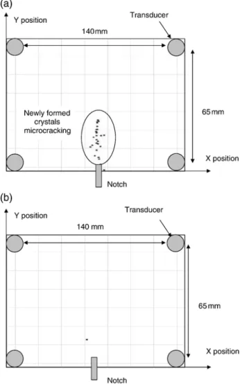
Fig. 12presents the maps for a specimen aged in water and for a specimen aged in air, both during 10 weeks. It is noticeable that acoustic activity appears for the healed specimen in the region of the initial crack, while nearly nothing is detected for a non-healed specimen. In view of the mechanical results which exhibit stiffness and strength recovery, one can say that in the first case, there is a damage of the newly formed crystals in the crack, and in the second case, there is only the re-opening of the existing crack, with very little acoustic activity (some due to friction probably). Note that for non-healed specimens, performing the same AE localisation analysis without removing the less energetic events would still provide little acoustic activity, less than that observed for healed specimens.
We may now consider the comparison during the reloading phase, not at the same CMOD, but at the same load level. Results at 90% of the peak load, in the post peak regime are analysed. Fig. 13 represents the location maps in terms of energy. Points representing the microcracks are plotted accord-ing to their acoustic energy in aJ (the analysis is carried out after having removed less energetic events): the bigger the point, the larger the energy. If we now sum these energies for events located below and above the pre-existing crack tip (which is for
height of 50 mm from the bottom face of the specimen), we can notice that 97% of the acoustic energy dissipated until 90% of the peak load is located in the pre-existing FPZ, for the specimen which has been stored in water, although it is 48% for a non-healed specimen. This acoustic energy dissipated in the crack for a healed specimen should be due mainly to microcracking of newly formed crystals inside the initial crack. Friction would provide some acoustic activity, but probably not the stiffness and strength recovery that was observed on the mechanical response at the same time. For the non-healed specimen, the acoustic activity is due to further propagation of existing microcracks (note that the specimen is again in the post peak regime).
5. Conclusion
The results of an experimental investigation on the mechanical behaviour of healed concrete specimens have been presented. After a controlled pre-cracking phase under three points bending, prismatic specimens are aged, in air or in water, during various durations ranging from 1 to 20 weeks. It appears that after storage in water exclusively, damaged beams tend to recover their initial global stiffness, and to improve slowly their flexural strength. The very specific concrete studied has an important amount of unhydrated cement available in its
Fig. 12. Microcracking maps, during the reloading phase (until 18μm — pre-peak regime) of specimens aged for 10 weeks; (a) ageing in water, (b) ageing in air.
Fig. 13. Energy location maps at 90% of the peak load in the post peak regime; (a) healed specimen, (b) non-healed specimen.
microstructure, and these observations are attributed to the self-healing of the pre-existing crack, mainly by hydration of anhydrous clinker on the crack surfaces. Recovery of stiffness can be related to the progressive filling of the crack by newly formed crystals, whose stiffness is close to those of primary C– S–H. The slow improvement of resistance can be explained by the progressive development of the mechanical properties of the newly formed crystals (whose structure might be different from bulk C–S–H) or of the weakness zone between new crystals and primary C–S–H.
Acoustic emission analysis was performed in order to confirm that the specific response observed for healed specimen is due indeed to some damaging process inside the existing crack. It also shows the two phases of the cracking process of healed concrete, comprising damage inside the existing crack and continuation of the crack propagation. All these investiga-tions have to be corroborated in the future with microscopic observations in order to clarify the chemical and physical mechanisms of the self-healing process and of the microcrack-ing processes of healed specimens.
References
[1] A. Neville, Autogenous healing — a concrete miracle? Concrete International (November 2002) 76–82.
[2] C. Edvardsen, Water permeability and autogenous healing of cracks in concrete, ACI Materials Journal 96 (4) (1999) 448–454.
[3] N. Hearn, C.T. Morley, Self-sealing property of concrete— experimental evidence, Materials and Structures 30 (1997) 404–411.
[4] N. Hearn, Self-sealing, autogenous healing and continued hydration: what is the difference? Materials and Structures 31 (1998) 563–567. [5] S. Jacobsen, E. Sellevold, Self healing of high strength concrete after
deterio-ration by freeze/thaw, Cement and Concrete Research 26 (1) (1996) 55–62. [6] S. Jacobsen, J. Marchand, H. Hornain, SEM observations of the
micro-structure of frost deteriorated and self healed concrete, Cement and Concrete Research 25 (8) (1995) 55–62.
[7] P. Pimienta, G. Chanvillard, Retention of the mechanical performances of Ductal® specimens kept in various aggressive environments, Fib — Symposium 2004, April 26–28, Avignon, France, 2004.
[8] N. Ter Heide, Crack healing in hydrating concrete, MSc thesis, Delft University of Technology, May 2005.
[9] A. Loukili, P. Richard, J. Lamirault, A study on delayed deformations of an ultra high strength cementious material, ACI, SP179-59, Recent Advances in Concrete Technology 179 (1998).
[10] P. Acker, Micromechanical analysis of creep and shrinkage mechanisms, in: F.-J. Ulm, Z.P. Bazant, F.H. Wittmann (Eds.), Creep, Shrinkage and Durability Mechanics of Concrete and Other Quasi-brittle Materials, Elsevier, Oxford UK, Aug. 2001.
[11] P. Acker, Swelling, shrinkage and creep: a mechanical approach to cement hydration, Concrete Science & Engineering 37 (2004) 237–243. [12] H.W. Reinhardt, M. Joos, Permeability and self-healing of cracked
concrete as a function of temperature and crack width, Cement and Concrete Research 33 (7) (2003) 981–985.
[13] H.R. Hardy Jr., Acoustic Emission/Microseismic Activity— Volume 1: Principles, Techniques, and Geotechnical Applications, A.A. Balkema Pubs, 2003.
[14] A. Proust, D. Marlot, J.C. Lenain, Application of acoustic emission to detect damage in concrete structures, illustrated with full scale examples, Concrete Solutions, 1st International Conference on Concrete Repair, July 15–17, 2003, Saint Malo, France, 2003.
[15] H. Rüsch, Research towards a general flexural theory for structural concrete, ACI Journal 57 (1960) 1–28.
[16] E.N. Landis, Micro–macro fracture relationships and acoustic emissions in concrete, Construction and Building Materials 13 (1999) 65–72. [17] B. Chen, J. Liu, Experimental study on AE characteristics of three-point
bending concrete beams, Cement and Concrete Research 34 (2004). [18] M. Othsu, T. Okamoto, S. Yugama, Moment tensor analysis of acoustic
emission for cracking mechanisms in concrete, ACI Structural Journal 95 (1998) 87–95.
[19] C.U. Grosse, J.H. Kurz, H.W. Reinhardt, Improvement of AE technique using wavelet algorithm, coherence functions and automatic data analysis, Construction and Building Materials 18 (2004) 203–213.
[20] K. Otsuka, H. Date, Fracture process zone in concrete tension specimen, Engineering Fracture Mechanics 65 (2–3) (2000) 111–131.
[21] K. Haidar, G. Pijaudier-Cabot, J.F. Dubé, A. Loukili, Correlation between the internal length, the fracture process zone and size effect in model materials, Materials and Structures 38 (2005) 201–210.
[22] H. Mihashi, N. Nomura, Correlation between characteristics of fracture process zone and tension-softening properties of concrete, Nuclear Engineering and Design 165 (1996) 359–376.
[23] K. Watanabe, J. Niwa, M. Iwanami, H. Yokota, Localized failure of concrete in compression identified by AE method, Construction and Building Materials 18 (2004) 189–196.
[24] J.H. Kurz, C.U. Grosse, H.W. Reinhardt, Strategies for reliable automatic onset time picking of acoustic emissions and of ultrasound signals in concrete, Ultrasonics 43 (2005) 538–546.
[25] B. Schechinger, Th. Vogel, H.W. Reinhardt, Acoustic emission for monitoring a reinforced concrete beam subject to four point bending, Construction and Building Materials 21 (3) (2007) 483–490.