Shear banding simulation in clay rock around an underground
opening, and its contact mechanism with the gallery’s lining
Fatemeh Salehnia, Robert Charlier
Université de Liége (ULg), Département ArGEnCo, Allée de la Découverte, 9, 4000 Liége, Belgium
F.Salehnia@alumni.ulg.ac.be
Abstract
Due to an underground excavation process in geological media, creation of a damaged zone with significant irreversible deformations and important host rock’s properties modifications is expected around the openings. This could result in the macro and microfracturing and a rearrangement of rock structures which may be potentially important, in the case of a geological disposal system for high-level nuclear waste, in terms of the long-term management of the system. This zone is called as Excavation Damaged Zone (EDZ). This study is aimed to simulate numerically the development of EDZ around a gallery excavated in a clay host-rock, through analyzing the evolution of strain localization approach in shear band mode. The initial anisotropic stress and cross-anisotropy of the elasto-plastic properties of the material are considered for a more realistic simulation. Additionally, to properly model the localization phenomenon and post-peak shear strength behavior, the coupled second gradient method is applied. Moreover, a particular analysis of the contact mechanism between the clay rock and the gallery’s lining is performed. Our study demonstrates some interesting features concerning the pressure excreted by the host rock on its interface with the lining upon contact, relatively to the development pattern of localized shear bands within the clay in the galley’s proximity.
Keywords: Excavation Damaged Zone, Shear bands, Strain Localization modeling, Host rock, Contact pressure
1.
I
NTRODUCTIONIn some countries, nuclear power is strategically and quantitatively an important contributor to many industries like the global electricity generation. As a result of the contribution of this energy, the production of highly radioactive waste is unavoidable. With regard to the harmfulness that arises from radioactivity of nuclear waste to man and the environment, they need to be carefully managed. Disposing the high-level and long-lived radioactive waste in the potential deep geological stable formation is a possible solution within the framework of their long-term management. The depth of a repository (several hundreds of meters) should ensure isolation from the biosphere. A very low hydraulic conductivity is one of the desirable properties for candidate host rocks [1] which ensures a limited radionuclide transport rates in the event that a loss of containment occurs due to the degradation of the engineered barrier system.
Clay formations in their natural state are considered suitable for hosting radioactive waste repositories in a number of European countries, because of their advantageous properties among which there is a very low hydraulic conductivity. A plastic clay rock formation located in the north of Belgium is the focus of this paper. This rock is studied as a possible host formation [2] considering its various favorable properties such as its good sorption capacity for many radioelements and, its self-sealing capacity as well as its very low hydraulic conductivity.
The Excavation Damaged Zone (EDZ) is expected, as a consequence of the underground excavations, to be created around the openings. Stress redistribution generated around the gallery may lead to the creation of a zone with significant irreversible deformations and changes of hydro-mechanical properties. Thence, the numerical simulation of EDZ, its extension and the fracturing network within this zone in the underground structure scale remains an essential issue. This issue of particular interest is the first main objective of our study.
The localized shear bands are commonly observed as a phenomenon leading up to failure in geomaterials, in the laboratory tests [3]. Similarly, in the field and during the construction of the underground
galleries within the studied clay host-rock, the shear induced fractures have been evidenced. In fact, in a progressive failure, these shear zones with localized plastic strain are realistically giving rise to the discontinuities, the rupture zones. Hence, to better understand the mechanisms leading to this fractures’ network, we propose to analyze the EDZ and its extension around the gallery, during its construction and in the long-term, by numerical modeling, in the framework of a strain localization approach in shear band mode.
The concrete lining has an essential role in case of the deep excavation of the underground galleries in the plastic clay. It could highly decrease the extent of damaged zone and the convergence around the gallery [4,5]. Thence, studying the contact mechanism on the interface between the clay mass and the lining around the gallery's opening is considered as the second main objective of this paper.
2.
T
HEORETICALF
ORMULATIONThe finite element code LAGAMINE, developed at Université de Liège [6] is used in our study, taking into account a deformable two-phase medium (i.e., solid and water).
The Drucker-Prager yield limit [7] (Figure 1a) in the framework of a frictional elasto-plastic model is used as the constitutive mechanical law for the rock while compressive stress is taken as negative:
0 tan 3 ˆ c c I m II F (1)
where c is the cohesion, ϕc is the compression friction angle, Iσ (=σij δij) is the first stress invariant, and the second deviatoric stress invariant, IIσ̂, is defined by Equation 3 in which σ^ij is the deviatoric stress tensor. m is also given as the following (Equation 2):
) sin 3 ( 3 sin 2 c c m (2) ij j ij ij ij I i II 3 ˆ , ˆ ˆ 2 1 ˆ (3)
In order to introduce the plastic cross-anisotropy of the material in our modeling, the cohesion is defined depending on the angle between major principle stress and the normal to the bedding plane (Equation 4) [8]. The behavior is considered to be isotropic in the plane of bedding and the direction of anisotropy is perpendicular to the bedding.
) 45 ( 0 1 ) 45 ( 0 ) 90 ( 0 ) 0 ( 0 1 ) 0 ( 0 ) 45 ( 0 0 45 45 ; 45 max orf orf orf orf orf orf orf c c c c c c c
(4)where c0 is the initial cohesion, and cf is the final cohesion (see Equation 8), and α1 is the angle between the direction of major principle stress and the normal vector to the bedding plane. The cohesion is assumed to be varied linearly in function of the angle α1, between the cohesion values which are defined for α1 =0°, α1
=45° and α1 =90°.
(a) (b)
Figure 1. (a) Representation of the Drucker-Prager yield surface in the principle effective stress space. (b) Schematic representation of the yield limit in the (Iσ IIσ̂ )plane, under ϕchardening and csoftening.
The behavior of the solid matrix is considered to be governed by the Terzaghi's postulate with the assumption of a fully water-saturated medium:
ij w ij ij
p
(5) where ij is the total stress tensor, ΄ij is the effective stress tensor, pw is the pore water pressure, and δij is the Kronecker symbol.The hardening and/or softening are introduced within this model (see Figure 1b) via an hyperbolic variation of friction angle and/or cohesion (Equations 7-8) as a function of Von Mises equivalent plastic strain (Equation 6) [9]: p p p ij ij eq ˆ ˆ 3 2 (6) p eq p eq c c B c cf 0 0 (7) p eq c p eq B c f c c c 0 0 (8)
where ϕc0 is the initial compression friction angle, ϕcf is the final compression friction angle, c0 is the initial cohesion, cf is the final cohesion, and Bϕ/Bc are the values of equivalent plastic strain for which half of hardening/softening on friction angle/cohesion is achieved.
Second gradient method:
With regard to the numerical computation of localized shear zones, the classical finite element method suffers from a pathological sensitivity to the mesh size in modeling of strain localization [5]. Hence, a specific approach is needed to overcome this problem in order to properly model the localization phenomenon and post-peak behavior. A last family of enriched models comes from continua with microstructure which is the case of local second gradient method [10,11]. This method is used in our coupled hydro-mechanical study as the regularization technique in which the continuum is enriched by the microstructure effects. Thus, the kinematics includes macrokinematics as well as microkinematics [12].
Equations 9-10 are two balance equations of the coupled second gradient model in the weak form which should be solved for every kinematically admissible virtual displacement field u*i and virtual pore water pressure field p*w:
d Gud tu TDu d x x u x u i i i i i i k i i ijk i i ij * * * * 2 * (9)
d Qp d qp d x p m p M q w w i w i w * * * * (10)where Ω is the current solid configuration (volume), Gi is the body force per unit volume, t̄i is the external traction (classical) forces per unit area, T̄i is an additional external (double) force per unit area that both t̄i and
T̄i applied on a part Γσ of the boundary of Ω, Du*i is the normal derivative of u*i, Ṁ is the time derivative of the water mass inside Ω, mi is the mass flow (see Equation 11), Q is a sink term, Γq is the part of the boundary where the input water mass per unit area q̄ is prescribed, and Σijk is the double stress, dual of the (micro) second gradient, which needs an additional constitutive law, and it has no link with the pore water pressure. Σijk in the second gradient law is defined with an elastic law [10] as a function of (micro) second gradient of the virtual displacement. It depends on one elastic parameter D to which the shear band width is proportional [12].
Using the Darcy's law which governs the water motion relation in an anisotropic porous medium, the water mass flow is given by:
2 , 1 , ; , j i j x w p w ij w k w i m (11)
The field equations are linearized and then they are discretized spatially using 2D plane strain isoparametric finite elements. More details on the corresponding formulation and discretization is out of the scope of this paper, and it may be found in [5,13] upon interest.
Contact problem:
With regard to the concrete lining of the studied gallery which has been emplaced almost simultaneously with the gallery excavation, the contact mechanism between the clay mass and the lining is an essential issue. The contact is supposed to occur during the gallery excavation while the clay converges towards the lining producing some contact pressure on the interface between two bodies. We propose using the hydro-mechanical interface elements between the clay mass and the concrete lining in order to model their contact phenomenon [5,6,14].
The frictional contact problems are usually treated by mean of elasto-plasticity analogy. A classical elasto-plastic model with the Coulomb yield criterion is used in our study as the mechanical constitutive law for contact behavior (see Equation 12 and Figure 2). We assume that when the contact occurs and two bodies are stuck, this sticking phase is equivalent to the elastic domain of the yield criterion (f<0). Then, the stick and slip states in the contact process would be distinguished by the yield surface (f=0). That is to say when the threshold value in the modulus of the tangential stress is reached, the slip conditions is verified.
N T
sl p
f
. (12)Figure 2. Representation of the Coulomb yield criterion.
The Penalty method has been implemented into Lagamine by [6] to regularize the sticking contact conditions. Hence, in the case of contact (p΄N>0), a slight penetration of one body into the other and, a tangential relative micro displacement between the contacting bodies could be possibly acceptable. Then, the rate of effective stresses is generally governed by:
T N T N T N g g K K p 0 0
(13)where ṗN and τ̇T are the rate of normal and tangential components of effective stress, ġN is the normal relative displacement (interpenetration) velocity, ġT is the (elastic) tangential microdisplacements velocity, and KN and KT are the penalty coefficients which control the tolerated penetration of the contacting bodies and their relative tangential microdisplacements, respectively.
3.
N
UMERICALS
IMULATION ANDR
ESULTSIn this section, the numerical simulation of the shear bands network and extension of EDZ consequently to the large scale gallery excavation through the studied host rock is presented by means of the strain localization approach. The simulated gallery is one of the main galleries excavated in the underground research laboratory (URL) close to the city of Mol in Belgium, in order to study the feasibility of high-level nuclear waste disposal in this clay formation.
The two-dimensional mesh geometry of the model is given in Figure 3. The gallery has an over-excavated radius of 2.49 m taken into account 40 cm of the concrete lining and 9 cm of the convergence between the massive and the lining. It must be noted that a simple elastic constitutive law using the total stresses is applied to model the concrete behavior. The hydro-mechanical interface elements are defined on the interface between the massive and the lining. The initial boundary conditions are indicated in Figure 3.
The anisotropic initial stresses are applied as yy =4.5 MPa and xx =3.8475 MPa MPa at the gallery level, which are decreased to 100 kPa on the gallery wall during the excavation phase (6 days) and remain constant until the end of simulation (3.5 years). Furthermore, the initial pore water pressure is equal to 2.25 MPa which there is a decrease up to the atmospheric pressure on the gallery wall during the excavation phase. Since the convergence of the clay mass due to the excavation is mostly taken place during the excavation phase, it is supposed that the contact between the massive and the lining occurs by there. From then on, the water pressure remains constant (equal to the atmospheric pressure) only on the internal surface of the concrete lining. The gravity effects are considered in our modeling as well.
Figure 3. Mesh geometry and boundary conditions of the model
Tables 1-3 show the parameters of the rock, concrete and their interface, respectively, used in the modeling. Most of the parameters have been defined with reference to a particular parametric study, as presented in [5], and with respect to the experimental work of [1]. Our aforementioned study has shown the role of the cohesion softening in order to initiate the strain localization around the opening.
Table 1- Clay parameters
Table 2- Concrete parameters Table 3- Interface parameters
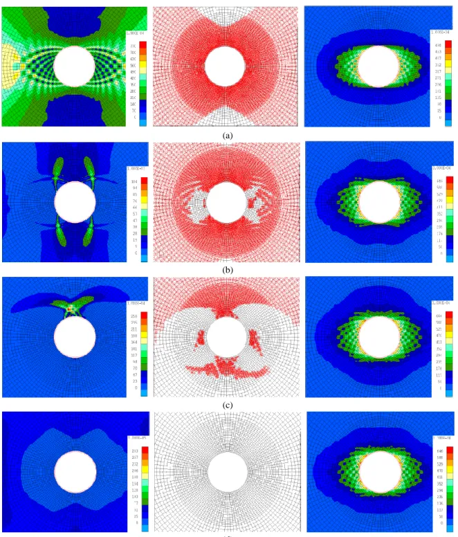
Figure 4 presents the increment of deviatoric strain, the total deviatoric strain and the plastic loading index in the vicinity of the gallery wall during the excavation phase (4, 5 and 6 days), and afterwards (3.5 years). The activity and distribution of the localized shear bands, and their evolutionary appearance and disappearance in different time steps can be observed by the contours of increment of deviatoric strain. However, the total deviatoric strain in each time step highlights the synthesis of the whole history of the
shear bands' activity in the accumulated time. The latter can underline the total extension of the localized shear bands around the gallery in a considered time. Moreover, the plastic loading index addresses the immediate response of the Gauss points in each element (here there are four Gauss points per element) in terms of the plasticity during the simulation.
(a) (b) (c) (d)
Figure 4. Increment of deviatoric strain (left), plastic loading index (middle), and total deviatoric strain (right) after (a) 4 days. (b) 5 days. (c) 6 days. (d) 3.5 years.
The onset of localized shear bands is observed after about 4 days. The evolutionary process of the extension of localized zone is although quite limited to the excavation period since no considerable activity is observed after the excavation phase: the increment of deviatoric strain does not show any remarkable activity of the shear bands after 6 days. Consistently, with regard to the total deviatoric strain (i.e. accumulation of the whole activity of the shear bands), the corresponding contour at the end of simulation is almost the same
as the one resulted at the end of excavation (compare Figures 4c and 4d). In fact, the total deviatoric strain after the end of excavation phase can be a reference of the extension of localized zone. Thus, the eye-shape (anisotropic) extension of the Excavation Damaged Zone (EDZ) around the gallery can be estimated as about 2.8 m horizontally and 0.6 m vertically (see also [15]).
The contact between the lining and the clay occurs during the excavation time, while the rock converges towards the lining, inducing the contact pressure on the interface between two bodies. From then on, it does not allow important evolution of shear bands around the gallery within the clay mass. Thus, it can have an essential impact on the reduction of EDZ [5,14,16].
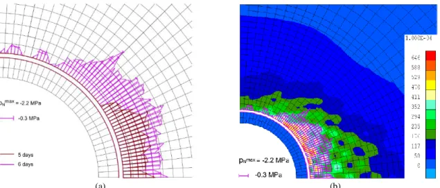
Figure 5a shows the diagram of the normal contact pressure on the interface between the lining and the clay mass after 5 days and 6 days (i.e. end of excavation), considering a quarter of the gallery. As it is observed, the contact is initiated on the horizontal side and then, it is developed on the whole interface until the end of excavation. In fact, due to the ovalization pattern in deformation of the clay mass during the excavation, the bottom elements firstly come in contact with the lining and normal contact pressure is established on the interface.
(a) (b) Figure 5. (a) Diagram of the normal contact pressure on the interface. (b) Superposition of the localized
shear bands and normal contact pressure on the interface after 6 days.
Moreover, some oscillations are observed in the evolution pattern of normal contact pressure on the interface. The oscillatory type of response has been studied to find out any possible numerical or physical origin. Our study has demonstrated that a physical aspect gives birth to these oscillations, and they are not originated numerically (see also [5,14]). That is to say the evolution pattern of the localized shear bands around the gallery. In fact, the oscillation of normal contact pressure on the interface is comparatively related to the shear bands created around the gallery. Figure 5b shows the superposition of the normal contact pressure on the interface (Figure 5a) and the total deviatoric strain within the clay around a quarter of the gallery (see Figure 4c) after 6 days. An essential accordance is noticed between these two phenomena. Indeed, the larger shear bands are reasonably compared with the peaks of the contact pressure produced on the interface. Furthermore, the both features affirm the anisotropic pattern of the clay response.
4.
C
ONCLUSIONSThe numerical simulation of the extension of Excavation Damaged Zone and the fracturing pattern inside this zone have been presented in this paper, taking into account their importance as the inevitable outcome of the gallery excavation in a deep geological formation. To do this, a finite element approach was used into which an elasto-plastic model with the Drucker-Prager yield surface in conjunction with the second gradient method have been incorporated. The gallery contains a concrete lining which is being in contact with the clay mass during the excavation phase. The creation and evolution of the localized shear zone within the clay mass was then reliably simulated. Furthermore, the progressive development of contact pressure, on the interface between the gallery’s lining and the rock, generated since the excavation time was analyzed. The impact of localized shear bands was fundamentally recognized as the basis of the oscillations observed in the contact pressure’s development pattern.
5.
A
CKNOWLEDGMENTThe financial support of ONDRAF/NIRAS (Belgian National Agency for Radioactive Waste and enriched Fissile Material) is gratefully acknowledged. This work is part of the first author's Ph.D. thesis.
6.
R
EFERENCES1. Bernier, F., Li, X. L., and Bastiaens, W. (2007),“Twenty-five years’ geotechnical observation and testing in the tertiary Boom clay formation”, Géotechnique, 57(2), pp. 229–237.
2. ONDRAF/NIRAS. (2001), “Technical overview of the safir 2 report: Safety assessment and feasibility interim report 2”, Technical Report NIROND 2001–05 E.
3. Bésuelle, P., Viggiani, G., Desrues, J., Coll, C., and Charrier, P. (2014),“A laboratory experimental study of the hydromechanical behavior of Boom clay”, Rock Mech. & Rock Eng., 47(1), pp. 143–155.
4. Salehnia, F., Charlier, R., Sillen, X., and Dizier, A. (2015), “Modeling of excavation damaged zone through the strain localization approach in boom clay”, Proc. of the 14th Int. Conference of International Association for Computer Methods and Recent Advances in Geomechanics, IACMAG 2014, pp. 335–340. 5. Salehnia, F. (2015), “From some obscurity to clarity in Boom Clay behavior: Analysis of its coupled
hydro-mechanical response in the presence of strain localization”, PhD thesis, Université de Liège. 6. Charlier, R. (1987), “Approche unifiée de quelques problèmes non linéaires de mécanique des milieux
continus par la méthode des éléments fini”, PhD thesis, Université de Liège.
7. Drucker, D. C. and Prager, W. (1952), “Soil mechanics and plastic analysis or limit design. Quarterly of applied mathematics”, 10.
8. François, B., Labiouse, V., Dizier, A., Marinelli, F., Charlier, R., and Collin, F. (2012), “Hollow cylinder tests on boom clay: Modelling of strain localization in the anisotropic excavation damaged zone”, Rock Mech. & Rock Eng., pp. 1–16.
9. Barnichon, J.-D. (1998), “Finite element modelling in structural and petroleum geology”, PhD thesis, Université de Liège.
10. Mindlin, R. (1964), “Micro-structure in linear elasticity. Archive for Rational Mechanics and Analysis”,
16(1), pp. 51–78.
11. Germain, P. (1973), “The method of virtual power in continuum mechanics. part 2: Microstructure”, SIAM Journal on Applied Mathematics, 25(3), pp. 556–575.
12. Chambon, R., Caillerie, D., and El Hassan, N. (1998), “One-dimensional localisation studied with a second grade model”, European Journal of Mechanics-A/Solids, 17(4), pp. 637–656.
13. Collin, F., Chambon, R., and Charlier, R. (2006), “A finite element method for poromechanical modelling of geotechnical problems using local second gradient models. International journal for numerical methods in engineering”, 65(11), pp.1749–1772.
14. Salehnia, F., Collin, F., Li, X. L., Dizier, A., Sillen, X., and Charlier, R. (2015), “Coupled modeling of excavation damaged zone in boom clay: Strain localization in rock and distribution of contact pressure on the gallery’s lining”, Computers and Geotechnics, 69, pp. 396–410.
15. Salehnia, F., Li, X. L., and Charlier, R. (2015), “Hydro-mechanical behavior of Boom clay host-rock in interaction with a deep excavated gallery’s lining”, Alert workshop 2015-Booklet of abstracts.
16. Salehnia, F., Charlier, R., and Levasseur, S. (2013), “Modeling of strain localization around the radioactive waste disposal galleries”, Proc. of the Coupled Phenomena in Environmental Geotechnics, CPEG 2013, pp. 443–45.