COMBRI DESIGN MANUAL
Part I: Application of Eurocode rules
A project carried out with a financial grant from the Research Fund for Coal and Steel (RFCS) of the European Community.
COMBRI DESIGN MANUAL
Part I: Application of Eurocode rules
A project carried out with a financial grant from the Research Fund for Coal and Steel (RFCS) of the European Community.
Although all care has been taken to ensure the integrity and quality of this publication and the information herein, no liability is assumed by the project partners and the publisher for any damage to property or persons as a result of the use of this publication and the information contained herein.
1st Edition
Copyright © 2008 by project partners
Reproduction for non-commercial purpose is authorised provided the source is acknowledged and notice is given to the project coordinator. Publicly available distribution of this publication through other sources than the web sites given below requires the prior permission of the project partners. Requests should be addressed to the project coordinator:
Universität Stuttgart
Institut für Konstruktion und Entwurf / Institute for Structural Design Pfaffenwaldring 7 70569 Stuttgart Germany Phone: +49-(0)711-685-66245 Fax: +49-(0)711-685-66236 E-mail: sekretariat@ke.uni-stuttgart.de
The present document and others related to the research project COMBRI+RFS-CR-03018 “Competitive Steel and Composite Bridges by Improved Steel Plated Structures” and the successive dissemination project RFS2-CT-2007-00031 “Valorisation of Knowledge for Competitive Steel and Composite Bridges”, which have been co-funded by the Research Fund for Coal and Steel (RFCS) of the European Community, can be accessed for free on the following project partners’ web sites:
Belgium: www.argenco.ulg.ac.be France: www.cticm.com
Germany: www.uni-stuttgart.de/ke, www.stb.rwth-aachen.de Spain: www.labein.es, www.apta.org.es
Sweden: cee.project.ltu.se
Cover pictures (from left to right):
Valley bridge Haseltal near Suhl, Germany, 2006 (© KE) Valley bridge Dambachtal near Suhl, Germany, 2005 (© KE)
Preface
This design manual is an outcome of the research project RFS-CR-03018 “Competitive Steel and Composite Bridges by Improved Steel Plated Structures - COMBRI” [7] and the successive dissemination project RFS2-CT-2007-00031 “Valorisation of Knowledge for Competitive Steel and Composite Bridges - COMBRI+” which have been funded by the Research Fund for Coal and Steel (RFCS) of the European Community. Within the RFCS research project essential knowledge has been acquired to enhance the competitiveness of steel and composite bridges and this has been incorporated in the design manual at hand which has been also presented in the frame of several seminars and workshops. The manual is subdivided into two parts to provide the reader with clearly arranged and concise documents:
► Part I: Application of Eurocode rules
In the research project the different national background of each partner how to apply and interprete Eurocode rules was brought together and a European melting pot of background information and general knowledge has been created. In order to maintain this valuable information two composite bridge structures - a twin-girder and a box-girder bridge - are covered in this part of the COMBRI Design Manual on the basis of worked examples for which the knowledge is written down in a descriptive manner. The examples include references to current Eurocode rules.
► Part II: State-of-the-Art and Conceptual Design of Steel and Composite Bridges
The national state-of-the-art in bridge design can be different so that firstly bridge types of the project partners’ countries - Belgium, France, Germany, Spain and Sweden - are introduced. They reflect the current practice in those countries and common bridge types as well as unusual bridges intended to solve special problems and some solutions being part of development projects are presented in Part II of the COMBRI Design Manual [8]. Also, improvements which can be provided to the design of steel and composite bridges are discussed and the possibilities and restrictions given by the current Eurocode rules are highlighted.
Moreover, the features of software EBPlate [13] developed in the research project to determine the elastic critical buckling stresses are presented in its contributive application for bridge design.
Finally, the authors of this design manual gratefully acknowledge the support and financial grant of the Research Fund for Coal and Steel (RFCS) of the European Community.
Ulrike Kuhlmann, Benjamin Braun
Universität Stuttgart, Institute for Structural Design / Institut für Konstruktion und Entwurf (KE) Markus Feldmann, Johannes Naumes
RWTH Aachen University, Institute for Steel Structures Pierre-Olivier Martin, Yvan Galéa
Centre Technique Industriel de la Construction Métallique (CTICM) Bernt Johansson, Peter Collin, Jörgen Eriksen
Luleå University of Technology, Division of Steel Structures (LTU) Hervé Degée, Nicolas Hausoul
Université de Liège, ArGEnCo Département José Chica
Fundación LABEIN
Joël Raoul, Laurence Davaine, Aude Petel
Service d'études sur les transports, les routes et leurs aménagements (Sétra)
Table of Contents
Notations ...V
1 Introduction and scope ...1
1.1 Introduction...1
1.2 Structure of the document...3
2 Description of the deck and global analysis...5
2.1 Twin-girder bridge...5
2.1.1 Longitudinal elevation...5
2.1.2 Transverse cross-section...5
2.1.3 Structural steel distribution...5
2.1.4 Construction phases...11
2.2 Box-girder bridge...15
2.2.1 Longitudinal elevation...15
2.2.2 Transverse cross-section...15
2.2.3 Structural steel distribution...17
2.2.4 Construction phases...19
2.3 General common data ...25
2.3.1 Reinforcement of the concrete slab ...25
2.3.1.1 Description of the slab reinforcement ...25
2.3.1.2 Modelling the slab to calculate the general longitudinal bending...25
2.3.2 Material properties...29
2.3.2.1 Structural steel...29
2.3.2.2 Concrete ...29
2.3.2.3 Reinforcement...31
2.3.2.4 Partial safety factors for materials...31
2.3.3 Actions...31
2.3.3.1 Permanent loads ...33
2.3.3.2 Concrete shrinkage...35
2.3.3.3 Creep – Modular ratios...37
2.3.3.4 Traffic loads ...39 2.3.3.5 Torque ...47 2.3.3.6 Thermal gradient ...49 2.3.4 Combinations of actions ...49 2.3.4.1 Design situations ...49 Page
2.3.4.2 General remarks ...49
2.3.4.3 ULS combinations other than fatigue ...51
2.3.4.4 SLS combinations ...51
2.4 Global analysis...53
2.4.1 General ...53
2.4.1.1 Concrete cracking ...53
2.4.1.2 Shear lag in the concrete slab...53
2.4.2 Internal forces and moments – Stresses...53
2.4.2.1 Numerical model...53
2.4.2.2 Effective width...55
2.4.2.3 Determination of the cracked zones around internal supports ...63
2.4.2.4 Shrinkage and cracked zones ...65
2.4.2.5 Organisation of the global analysis calculations ...65
2.4.2.6 Results...69
3 Cross-section verifications ...79
3.1 Twin-girder bridge...79
3.1.1 General ...79
3.1.2 Check of cross-section at the end support C0...81
3.1.2.1 Geometry...81
3.1.2.2 Material properties ...83
3.1.2.3 Internal forces and moments ...85
3.1.2.4 Determination of the cross-section class...85
3.1.2.5 Plastic section analysis...87
3.1.3 Check of cross-section at mid-span C0-P1...95
3.1.3.1 Geometry...95
3.1.3.2 Material properties ...95
3.1.3.3 Internal forces and moments ...95
3.1.3.4 Determination of the cross-section class...95
3.1.3.5 Plastic section analysis...95
3.1.4 Check of cross-section at mid-span P1-P2 ...97
3.1.4.1 Geometry...97
3.1.4.2 Material properties ...99
3.1.4.3 Internal forces and moments ...101
3.1.4.4 Determination of the cross-section class...101
3.1.4.5 Plastic section analysis...103
3.1.5 Check of cross-section at the internal support P2...107
3.1.5.1 Subpanel 1 - Geometry...107
3.1.5.4 Subpanel 1 - Determination of the cross-section class...111
3.1.5.5 Subpanel 1 - Elastic section analysis ...115
3.1.5.6 Subpanel 2 - Geometry...128
3.1.5.7 Subpanel 2 - Material properties ...128
3.1.5.8 Subpanel 2 - Internal forces and moments ...128
3.1.5.9 Subpanel 2 - Determination of the cross-section class...128
3.1.5.10 Subpanel 2 - Elastic section analysis ...128
3.1.5.11 Subpanel 3 - Geometry...132
3.1.5.12 Subpanel 3 - Material properties ...134
3.1.5.13 Subpanel 3 - Internal forces and moments ...134
3.1.5.14 Subpanel 3 - Determination of the cross-section class...134
3.1.5.15 Subpanel 3 - Elastic section analysis ...134
3.2 Box-girder bridge...139
3.2.1 General ...139
3.2.2 Check of cross-section at mid-span P1-P2 ...141
3.2.2.1 Geometry...141
3.2.2.2 Material properties ...143
3.2.2.3 Internal forces and moments ...143
3.2.2.4 Reduction due to shear lag effect ...145
3.2.2.5 Determination of the cross-section class...145
3.2.2.6 Bending resistance verification ...147
3.2.2.7 Shear resistance verification ...147
3.2.2.8 Interaction between bending moment and shear force...153
3.2.3 Check of cross-section at the internal support P3...153
3.2.3.1 Geometry...153
3.2.3.2 Material properties ...155
3.2.3.3 Internal forces and moments ...157
3.2.3.4 Mechanical properties of the gross cross-section...157
3.2.3.5 Effective area of the bottom flange...159
3.2.3.6 Effective area of the web...175
3.2.3.7 Bending resistance verification ...181
3.2.3.8 Shear resistance verification ...181
3.2.3.9 Interaction between bending moment and shear force...191
4 Verifications during erection...195
4.1 Twin-girder bridge...195
4.1.1 General ...195
4.1.2 Verifications according to Sections 6 and 7, EN 1993-1-5 ...199
4.1.3 Verifications according to Section 10, EN 1993-1-5...201
4.2 Box-girder bridge...211
4.2.1 General ...211
4.2.2 Verifications according to Section 6, EN 1993-1-5...217
4.2.2.1 Launching situation “1” ...217
4.2.2.2 Launching situation “2” ...223
4.2.2.3 Launching situation “3” ...223
4.2.3 Verifications according to Section 10, EN 1993-1-5...225
4.2.3.1 Webpanel (Launching situation “1” only) ...225
4.2.3.2 Bottom plate...243 4.2.4 Results ...263 5 Summary ...267 References ...271 List of figures ...273 List of tables ...277
Notations
Small Latin lettersa Length of a web plate between adjacent vertical stiffeners (possible lower indices: p, w) bb Width of the bottom flange
bbf Width of the bottom flange of the beam
beff Effective width of the concrete slab
bi Actual geometric width of the slab associated to the main girder
btf Width of the top flange of the beam
bp Width of the panel
bslab Thickness of the concrete slab
bsub Width of each subpanel of the bottom flange
b0 Center-to-center distance between the outside stud rows
b1 Distance between webs of stiffener
b2 Width of stiffener flange
b3 Width of each stiffener web
cbf Part of the bottom flange subject to compression
cw Part of the web subject to compression
clr Distance between the centroid of each lower longitudinal reinforcing steel layer and the
near free external surface
cur Distance between the cenroid of each upper longitudinal reinforcing steel layer and the
near free external surface e Thickness of the concrete slab
fcd Design value of concrete compressive strength
fck Characteristic compressive cylinder strength at 28 days
fctk,0.05 5% fractile of the characteristic axial tensile strength
fctk,0.95 95% fractile of the characteristic axial tensile strength
fctm Mean value of axial tensile strength
fcm Mean value of concrete cylinder strength at 28 days
fsk Yield strength of the reinforcing steel bars
fu Ultimate stress of the structural steel
fy Yield strength of the structural steel (possible lower indices: w, tf, tf1, tf2, tst, p)
fyd Design yield strength (possible lower indices: w, tf, tf1, tf2, tst, p)
h Height of the beam
ha,seff Effective elastic neutral axis (ENA) of the structural steel part only
hw Height of the web of the beam
hw,eff Effective height of the web in compression of the beam
hwe1,2 Distribution of the effective height of the web in compression of the beam
hst Height of stiffener
kσ Plate buckling coefficient for normal stress (possible lower indices: c, p, w, pw, pbf,
LT, op)
kτ Plate buckling coefficient for shear stress
kτ,st Plate buckling coefficient for shear stress for plate with longitudinal stiffeners
mq Torque loads due to distributed loads
nlr Total number of steel reinforcement in lower layer
n, n0 Structural steel / concrete modular ratio for short-term loading
nL Structural steel / concrete modular ratio for long-term loading
nst Number of stiffeners (equally spaced) of the bottom flange
nur Total number of steel reinforcement on in upper layer
p Perimeter of the concrete slab q Eccentric distributed traffic loads
qfk Characteristic value of the uniformly distributed load due to pedestrian and
cycle traffic
qmin Minimum value of the line load due to bridge equipment
qmax Maximum value of the line load due to bridge equipment
qnom Nominal value of the line load due to bridge equipement (safety devices,
pavement, …)
slr Spacing in lower layer of steel reinforcement of the concrete slab
sur Spacing in upper layer of steel reinforcement of the concrete slab
t Plate thickness (possible lower indices: tf, tf1, tf2, p, w, st) t Time
t0 Age of the concrete put in place at each construction phase
tf Thickness of the flange of the beam (possible lower indices: 1, 2)
tini Time at traffic opening
tslab Thickness of the concrete slab
tst Thickness of stiffener
tst,eq Equivalent thickness of stiffener web
tw Thickness of the web of the beam
w Width of all traffic lanes
x Abscissa of bridge
z Position of the centre of gravity of the cross-section
zna Position of the centre of gravity of the composite cross-section
Capital Latin Letters
Aa Cross-sectional area of the structural steel section
Aabf Cross-sectional area of the bottom flange
Aa, eff Effective cross-sectional area of the steel structural part only
Aatf Cross-sectional area of the top flange (possible lower indices: 1, 2)
Aaw Cross-sectional area of the web
Ac Total cross-sectional area of the concrete slab; Gross area of the bottom flange with
stiffeners neglecting parts supported by adjacent plate elements Ac.eff.loc Effective local area of the bottom flange with stiffeners
Aclr Cross-sectional area of the concrete located under the lower layer of steel reinforcement
of the slab
Aclur Cross-sectional area of the concrete located between the lower and upper layer of steel
reinforcement of the slab
Acur Cross-sectional area of the concrete located above the upper layer of steel
reinforcement of the slab
Aeff Effective cross-sectional area of the composite cross-section
Aslr Cross-sectional area of one steel reinforcement of the lower layer of the slab
Astw Cross-sectional area of the web stiffener
Asur Cross-sectional area of one steel reinforcement of the upper layer of the slab
Atot Gross cross-sectional area of the composite cross-section
Atslr Cross-sectional area of the total steel reinforcement of the lower layer of the slab
Atsur Cross-sectional area of the total steel reinforcement of the upper layer of the slab
Ea Elasticity modulus of structural steel
Ecm Elasticity modulus of concrete
Es Elasticity modulus of reinforcing steel
Gk Characteristic (nominal) value of the effect of permanent actions
Gk,inf Characteristic value of a favourable permanent action (nominal value of self-weight and
minimum value of non-structural equipments) taking account of construction phases Gk,sup Characteristic value of an unfavourable permanent action (nominal value of self-weight
and maximum value of non-structural equipments) taking account of construction phases
I Second moment of area
Ia,eff Effective second moment of area of the structural steel part
Ieff Effective second moment of area of the cross-section
It The St. Venant torsional stiffness
Itot Gross second moment of area of the composite bridge
IΔ Second moment of area (around a horizontal axis Δ located at the steel/concrete
interface)
Le Equivalent span length in the considered cross-section
Ma,Ed Design bending moment acting on the structural steel cross-section
Mc,Ed Design bending moment acting on the composite cross-section
Mf,Rd Design value of the plastic resistance moment of a cross-section consisting of the
flanges only
MEd Design bending moment
Mpl,Rd Design value of the plastic bending moment resistance
MQ Torque loads due to concentrated loads
Na Design value of the plastic normal force resistance of the structural steel cross-section
Nabf Design value of the plastic normal force resistance of the structural steel bottom flange
Natf Design value of the plastic normal force resistance of the structural steel top flange
Naw Design value of the plastic normal force resistance of the structural steel web
Nc Design value of the plastic normal force resistance of the concrete slab in compression
Nclr Design value of the plastic normal force resistance of the concrete in compression
located under lower layer of steel reinforcement
Ncur Design value of the plastic normal force resistance of the concrete in compression
located above upper layer of steel reinforcement
Nclur Design value of the plastic normal force resistance of the concrete in compression
located between lower and upper layer of steel reinforcement
Nsl Design value of the plastic normal force resistance of the lower layer of steel
reinforcement
Nsu Design value of the plastic normal force resistance of the upper layer of steel
reinforcement
Q Eccentric concentrated traffic loads
Qk1 Characteristic value of the leading variable action 1
Qki,i≥2 Characteristic value of the accompagning variable action i
S Envelope of characteristic values of internal forces and moments (or deformations) due
to concrete shrinkage
Sna Gross first moment of area of the composite cross-section
TSk Envelope of characteristic values of internal forces and moments (or deformations) due
to the vertical concentrated loads from Load Model no. 1 in EN 1991-2
UDLk Envelope of characteristic values of internal forces and moments (or deformations) due
to the vertical uniformly distributed loads from Load Model no. 1 in EN 1991-2 Vb,Rd Design value of the shear resistance in case of shear plate buckling in the structural
steel web
Vbf,Rd Design value of the shear resistance of the flange in case of shear plate buckling in the
structural steel web
Vbw,Rd Design value of the shear resistance of the web in case of shear plate buckling in the
structural steel web
VEd Design shear force
VEd, proj Projection of the design shear force in the direction of the web
VRd Design value of the shear resistance
Small Greek letters
α Factor; angle; compressed height percentage
αQi Adjustment factor on concentrated load TS of LM1 on lanes i (i = 1, 2, …)
αqi Adjustment factor on uniformly distributed load UDL of LM1 on lanes i (i =1, 2,…) αqr Adjustment factor on load model LM1 on the remaining area
β Reduction factor for shear lag effect
γC Partial safety factor for resistance of concrete γM Partial safety factor for resistance of structural steel
γM0 Partial safety factor for resistance of structural steel (Yielding, local instability) γM1 Partial safety factor for resistance of structural steel (Resistance of members to
instability)
γM2 Partial safety factor for resistance of structural steel (Resistance of joints)
γM,ser Partial safety factor for resistance of structural steel at Serviceability Limit State (SLS) γS Partial safety factor for resistance of reinforcing steel
ε Strain; factor 235 / ²
y
N mm
f (possible lower indices: tf, tf1, tf2, p, w, st)
εca Autogenous shrinkage strain εcd Drying shrinkage strain εcs Total shrinkage strain
η Coefficient of the yield strength of structural steel
1
η ; η 3 Ratio between applied stress and yield strength in a structural steel cross-section
1
η ; η 3 Ratio between applied force and resistance in a structural steel cross-section
θω Incline angle of the web with reference to the vertical direction κ Factor to take into account shear lag
λ Reduced slenderness (possible lower indices: c, p, w, pw, pbf, LT, op)
μ Moment of area
ν Poisson’s ratio
σabfu Stress at the upper edge of the bottom flange (possible lower indices: eff) σabfl Stress at the lower edge of the bottom flange (possible lower indices: eff) σatfl Stress at the lower edge of the top flange (possible lower indices: eff) σatfu Stress at the upper edge of the top flange (possible lower indices: eff) σc Longitudinal upper fibre tensile stress in the concrete slab
σcr Elastic critical plate buckling stress σE Elastic critical Euler’s stress
σEd Design value of a direct stress in a cross-section
σtsur Stress in the upper reinforcement of the concrete slab (possible lower indices: eff) σsup,reinf Maximal ULS Stress in the upper reinforcement of the concrete slab in the cracked
behaviour (sagging moment)
ρ Reduction factor (≤ 1,0) for effective area of a structural steel cross-section
ρc Reduction factor for effectivep width
ρs Reinforcement ratio in a concrete cross-section τcr Elastic critical shear buckling stress
τEd Design value of a shear stress in a cross-section
ϕ Creep function
φ Diameter of the steel reinforcement of the concrete slab
φlr Diameter of the upper steel reinforcement of the concrete slab φur Diameter of the upper steel reinforcement of the concrete slab χ Reduction factor (≤ 1) for instability (possible lower indices: c, p, w)
ψ Stress ratio between opposite edges of a structural steel plate (possible lower
indices: w)
ψL Creep multiplier for modular ratio
ψ0 Factor for the combination value of a variable action ψ1 Factor for the frequent value of a variable action
ψ2 Factor for the quasi-permanent value of a variable action
1 Introduction and scope
1.1 Introduction
In the COMBRI research project [7], in which this design manual has its origin, the different national background of each partner how to apply and interprete Eurocode rules was brought together and a European melting pot of background information and general knowledge has been created. In order to facilitate the implementation of Eurocodes EN 1993-1-5, EN 1993-2 and EN 1994-2 with regard to plate buckling verifications, it was decided to cover two steel-concrete composite bridges - a twin-girder and a box-twin-girder bridge - in order to present the knowledge with the help of worked examples and in a very descriptive manner. As the examples focus in detail on the application and interpretation of Eurocode rules which are related to plate buckling verifications, the overall view on bridge design cannot be covered. In this context, Figure 1-1 shows how many standards can be involved in the design of a composite bridge. Here, we are mainly dealing with EN 1993-1-5 “Plated Structural Elements”, EN 1993-2 “Steel bridges” and EN 1994-2 “Composite bridges”.
EN 1994 - 2 Composite bridges EN 19 92 - 2 Conc rete b ridges Steel b ridges EN 199 3 - 2 ActioEN 199ns 1 EN 19 90 Basis of de sign Pa rt 1 11 Cab les Par t 1 10 Brit tle fr actu re Par t 1 - 9 Fatig ue Part 1 - 8 Join ts Part 1 - 5 Stiffened pla tes Part 1 - 1
General rules - steel
Ann ex A2 Applica tion for brid ges The rmal actio ns Part 1 - 5 Part 1 - 1 Permanent a ctions Part 1 - 4 Wind Par t 1 - 6 Actio ns d urin g ex ecut ion Par t 1 - 7 A ccid enta l act ions P art 2 T raffic Part 1 - 1 General ru les - concre te
Figure 1-1: Eurocodes to be used in a composite bridge design.
In some parts, this design manual introduces general assumptions e.g. on actions without aiming to present the theoretical background or the modelling in detail. In addition to that, it is assumed that the reader is familiar with general design and modelling issues of bridges because this design manual gives a detailed view on plate buckling topics but it can of course not cover all other topics related to the verification of the design. For further information to the aforementioned topics, the reader is referred to e.g. [2], [4], [6], [32], [33], [34], [35], [36], [37], [39], [41]. However, this summary of references does not attempt to provide a comprehensive overview on available literature so that much more excellent work may exist which is not mentioned here.
The design of steel and composite bridges according to the Eurocodes
For the design of steel and composite bridges the following Eurocodes are mandatory [3]: • EN 1990/A1 Eurocode: Basis of structural design – Application for bridges [14] • EN 1991-1-1 Eurocode 1: Actions on structures – Part 1-1: General actions -
Densities, self-weight, imposed loads for buildings [15]
• EN 1991-1-3 Eurocode 1: Actions on structures – Part 1-3: General actions, Snow
loads [16]
• EN 1991-1-4 Eurocode 1: Actions on structures – Part 1-4: General actions, Wind
actions [17]
• EN 1991-1-5 Eurocode 1: Actions on structures – Part 1-5: General actions, Thermal
actions [18]
• EN 1991-1-6 Eurocode 1: Actions on structures – Part 1-6: General actions, Actions during execution [19]
• EN 1991-1-7 Eurocode 1: Actions on structures – Part 1-7: General actions, Accidental actions [20]
• EN 1991-2 Eurocode 1: Actions on structures – Part 2: Traffic loads on
bridges [21]
• EN 1993-1-1 Eurocode 3: Design of steel structures – Part 1-1: General rules and rules for buildings [22]
• EN 1993-1-5 Eurocode 3: Design of steel structures – Part 1-5: Plated structural
elements [23]
• EN 1993-2 Eurocode 3: Design of steel structures – Part 2: Steel Bridges [24] • EN 1994-1-1 Eurocode 4: Design of composite steel and concrete structures –
Part 1-1: General rules and rules for buildings [25]
• EN 1994-2 Eurocode 4: Design of composite steel and concrete structures – Part 2: General rules and rules for bridges [26]
• EN 1997-1 Eurocode 7: Geotechnical design – Part 1: General rules [27] • EN 1998-1 Eurocode 8: Design of structures for earthquake resistance –
Part 1: General rules, seismic actions and rules for buildings [28] • EN 1998-2 Eurocode 8: Design of structures for earthquake resistance –
Part 2: Bridges [29]
• EN 1998-5 Eurocode 8: Design of structures for earthquake resistance – Part 5: Foundations, retaining structures and geotechnical aspects [30] Throughout the document, references to the Eurocodes used herein is given.
1.2 Structure of the document
In the following, the worked examples are presented in a double-sided layout with comments, background information and interpretation issues on the left-hand side and the example calculation on the right. All relevant references to current Eurocode rules are provided. As mentioned above, the examples are a twin-girder and a box-girder bridge which allows to look basically at a design without and with longitudinal stiffeners.
In Chapter 2 the deck of the twin-girder and the box-girder bridge is described and the global analysis of both bridges is introduced. For this purpose, an overview on the bridge geometry, material distribution and construction sequences is given firstly. Secondly, a general section follows in which common data such as material properties and actions as well as combinations thereof are given. Last but not least, the global analysis is presented for both bridges and the relevant results - internal forces and moments - are summarised for the verifications. Based on that, Chapters 3 and 4 look at the verifications during the final stage and the execution stage. Here, each chapter is subdivided into a part dealing with the verifications of the twin-girder bridge or the box-girder bridge.
2 Description of the deck and global analysis
2.1 Twin-girder bridge
2.1.1 Longitudinal elevation
The bridge is a symmetrical twin-girder composite structure with three spans of 50 m, 60 m and 50 m (i.e. a total length between abutments of 160 m). This is a theoretical example for which a few geometrical simplifications have been made:
• Straight horizontal alignment • Flat top face of the deck • Straight bridge
• Constant height of 2400 mm for the structural steel main girders
50.00 m 60.00 m 50.00 m
C0 P1 P2 C3
Figure 2-1: Elevation of the twin-girder bridge.
2.1.2 Transverse cross-section
The bridge carries a two-lane traffic road.with two 3.5 m wide lanes, hard shoulders of 2 m width on each side and a standard safety barrier (see Figure 2-2).
The transverse cross-section of the concrete slab and of the non-structural equipment is symmetrical with reference to the axis of the bridge. The slab thickness varies from 0.4 m above the main girders to 0.25 m at its free edges, but it has been modelled as a 0.325 m deep rectangular cross-section.
The total slab width is 12 m. The centre-to-centre spacing between main girders is 7 m and the slab cantilever on each side is 2.5 m.
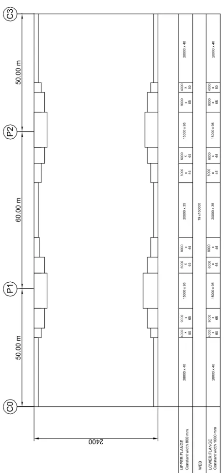
2.1.3 Structural steel distribution
The structural steel distribution for a main girder is presented in Figure 2-4.
Each main girder has a constant depth of 2400 mm and the variations in thickness of the upper and lower flanges face towards the inside of the girder. The lower flange is 1000 mm wide whereas the upper flange is 800 mm wide.
3.50 3.50 7.00 2.50 12.00 2.50 2.00 2.00 Girder no 1 Girder no 2 2.4
Figure 2-2: Cross-section with traffic data of the twin-girder bridge.
The two main girders have transverse bracings on abutments and on internal supports as well as every 8.333 m in side spans (C0-P1 and P2-C3) and every 7.5 m in the central span (P1-P2). Figure 2-3 illustrates the geometry adopted for this transverse cross-bracing on supports. In order to justify the shear resistance of the internal support sections, vertical stiffeners are added at 1.5 m and at about 4 m from the internal supports.
The optimisation of the stiffening will be discussed in Design Manual Part II [8], according to the results of COMBRI research project [7].
2400 7000 2.00 3.50 2.00 2.5% 3.50 2.5%
50.00 m 60.00 m 50.00 m C0 P1 P2 C3 Const ant widt h 800 mm UPPER FLANGE LO WER FLANG E WEB Const ant widt h 1000 mm 28000 x 40 28000 x 40 4000 x 50 4000 x 50 9000 x 65 9000 x 65 15000 x 95 15000 x 95 6000 x 65 6000 x 65 8000 x 45 8000 x 45 20000 x 35 19 x160000 20000 x 35 28000 x 40 28000 x 40 4000 x 50 4000 x 50 9000 x 65 9000 x 65 15000 x 95 15000 x 95 6000 x 65 6000 x 65 8000 x 45 8000 x 45 2400
EN 1994-2, 6.6.5.2(3)
(3) In execution, the rate and sequence of concreting should be required to be such that partly matured concrete is not damaged as a result of limited composite action occurring from deformation of the steel beams under subsequent concreting operations. Wherever possible, deformation should not be imposed on a shear connection until the concrete has reached a cylinder strength of at least 20 N/mm2.
EN 1994-2, 5.4.2.4, Stages and sequence of construction
(1)P Appropriate analysis shall be made to cover the effects of staged construction including where necessary separate effects of actions applied to structural steel and to wholly or partially composite members.
(2) The effects of sequence of construction may be neglected in analysis for ultimate limit states other than fatigue, for composite members where all cross-sections are in Class 1 or 2 and in which no allowance for lateral-torsional buckling is necessary.
2.1.4 Construction phases
The assumptions regarding the construction phases are important for all the verifications during erection of the structural steel structure of the deck and during concreting. They are also necessary to determine the values of steel/concrete modular ratios (see Paragraph 2.3.3.3). Finally, the calculation of internal forces and moments in the deck should take construction phases into account (EN 1994-2, 5.4.2.4). The following construction phases have been adopted:
• Erection of the structural steel structure by launching (see Section 4.1)
• On-site pouring of the concrete slab segments by casting them in a selected order:
The total length of 160 m has been broken down into 16 identical 10-m-long concreting segments. They are poured in the order indicated in Figure 2-5. The start of pouring the first slab segment is the time origin (t = 0). Its definition is necessary for determining the respective ages of the concrete slab segments during the construction phasing.
The time taken to pour each slab segment is assessed to three working days. The first day is devoted to the concreting, the second day to its hardening and the third day to moving the mobile formwork. The slab is thus completed within 48 days (EN 1994-2, 6.6.5.2(3)).
• Installation of non-structural equipments:
It is assumed to be completed within 32 days, so that the deck is fully constructed at the date t = 48 + 32 = 80 days.
Given these choices, Table 2-1 shows the ages of the various slab segments and the mean value of the age t0 for all the concrete put in place at each construction phase.
1 2 3 16 15 14 4 5 6 7 13 12 11 10 9 8 1 2 3 4 160.00 m 10.00 m 50.00 m 60.00 m 50.00 m
Table 2-1: Age of concrete slab segments at the end of the construction phasing of the twin-girder bridge.
2.2 Box-girder bridge
2.2.1 Longitudinal elevation
The bridge is a symmetrical box-girder composite structure with five spans of 90 m, 3 x 120 m and 90 m (i.e. a total length between abutments of 540 m). This is a theoretical example for which a few geometrical simplifications have been made:
• Straight horizontal alignment • Flat top face of the deck • Straight bridge
• Constant height of 4000 mm for the structural steel box-girder
90.00 m 120.00 m 120.00 m 120.00 m 90.00 m
C0 P1 P2 P3 P4 C5
Figure 2-6: Elevation of the box-girder bridge.
2.2.2 Transverse cross-section
The bridge carries a four-lane traffic road. Each lane is 3.50 meter wide and the two outside ones are bordered by a 2.06 meter wide safety lane. Standard safety barriers are located outside the traffic lanes and at the middle of the slab width (see Figure 2-7).
The transverse cross-section of the concrete slab and of the non-structural equipment is symmetrical with reference to the axis of the bridge. The 21.50 m wide slab has been modelled with a theoretical constant thickness of 0.325 m. The centre-to-centre spacing between the webs in the upper part is 12.00 m and the slab cantilever on each side is 4.75 m.
4. 00 2.06 3.50 3.50 21.50 6.70 12.00 2.10 3.50 3.50 2.06 6.50 4. 00 6.70 0.50 0.50 0. 50 0,20 4.75 1.50
The concrete slab is connected to an open box section with the following features: • total depth: 4.00 m
• centre-to-centre distance between the webs in the upper part: 12.00 m • centre-to-centre distance between the webs in the lower part: 6.50 m • width of upper flanges: 1.50 m
• width of lower flange: 6.70 m
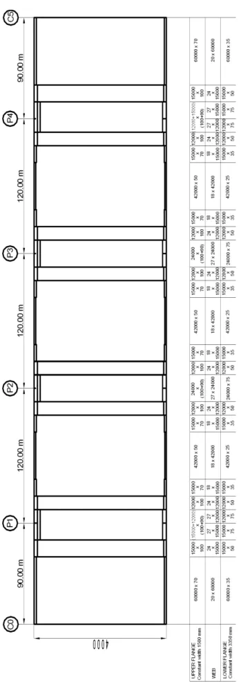
2.2.3 Structural steel distribution
The structural steel distribution is presented in Figure 2-10.
The box-girder has a constant depth of 4000 mm and the variations in thickness of the upper and lower flanges face towards the inside of the box-girder. The bottom flange is 6700 mm wide whereas the upper flanges are 1500 mm wide. An additional upper flange is necessary around the intermediate supports. It is located below the main upper flange, so that the total height of the box-girder is always equal to 4000 mm. The width of this additional upper flange is 1400 mm.
An additional steel rolled I-girder, which is located along the longitudinal bridge axis of symmetry, has been connected to the concrete slab. It helps during the concreting phases of the slab and participates in the resistance of the composite cross-section as additional section for the upper steel flanges.
The box section has transverse frames on abutments and on internal supports as well as every 4.0 m in side and central spans. Figure 2-8 illustrates the adopted geometry of this transverse cross-bracing on supports.
In order to justify the shear resistance in the webpanels adjacent to an intermediate support, transverse frames are added at 2.5 m from the internal supports.
Ax
is
of the b
ridge
Figure 2-8: Transverse cross-bracings on supports of the box-girder bridge.
Figure 2-9 illustrates the dimensions of the bottom flange longitudinal trapezoidal stiffeners. The thickness is 15 mm for the webs and the flange of the stiffeners. They are continuous along the whole bridge, whereas web longitudinal stiffeners are only used for the panels surrounding the intermediate supports. The web longitudinal stiffeners have the same dimensions as the bottom flange longitudinal stiffeners; they are located at mid-depth of the webs. They have been added to justify the shear resistance of the web.
The stiffening design has been made following the recommendations of the COMBRI research project [7], leading to dimensions which are bigger than the classical ones.
EN 1994-2, 6.6.5.2(3)
(3) In execution, the rate and sequence of concreting should be required to be such that partly matured concrete is not damaged as a result of limited composite action occurring from deformation of the steel beams under subsequent concreting operations. Wherever possible, deformation should not be imposed on a shear connection until the concrete has reached a cylinder strength of at least 20 N/mm2.
EN 1994-2, 5.4.2.4, Stages and sequence of construction
(1)P Appropriate analysis shall be made to cover the effects of staged construction including where necessary separate effects of actions applied to structural steel and to wholly or partially composite members.
(2) The effects of sequence of construction may be neglected in analysis for ultimate limit states other than fatigue, for composite members where all cross-sections are in Class 1 or 2 and in which no allowance for lateral-torsional buckling is necessary.
0.50 0.20
0.01
5
0.50
Figure 2-9: Detail of a bottom flange longitudinal stiffener of the box-girder bridge.
NOTE1: On the intermediate supports, an additional upper flange of 1400 mm x 90 mm is welded to the main upper flange.
NOTE2: Different thickness ratios could be obtained by using S355 with quality M or ML around the intermediate supports. Indeed, according to EN 10025-3, by using steel S355 N/NL the main upper flange thickness is limited to 100 mm to keep a yield strength equal to 315 MPa, whereas according to EN 10025-4 by using S355 M/ML the yield strength is equal to 320 MPa for up to 120 mm thick plates. So a design in steel S355 M/ML allows a main 120 mm thick upper flange and an additional 70 mm thick upper flange at intermediate supports. The choice of plate thickness should also fulfil the requirements of EN 1993-1-10, Table 2.1.
NOTE3: An alternative design with a single upper flange made of S 460 is studied in Design Manual Part II, Chapter 3 [8].
2.2.4 Construction phases
The assumptions regarding the construction phases are important for all verifications during erection of the structural steel structure of the deck and during concreting. They are also necessary to determine the values of steel/concrete modular ratios (see Paragraph 2.3.3.3). Finally the calculation of internal forces and moments in the deck should take construction phases into account (EN 1994-2, 5.4.2.4).
The following construction phasing has been adopted:
• Erection of the structural steel structure by launching (see Section 4.2);
• On-site pouring of the concrete slab segments by casting them in a selected order:
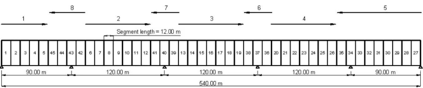
The total length of 540 m has been broken down into 45 identical 12-m-long concreting segments. They are poured in the order indicated in Figure 2-11. The start of pouring the first slab segment is the time origin (t = 0). Its definition is necessary to determine the respective ages of the concrete slab segments during the construction phasing.
The time taken to pour each slab segment is assessed to three working days. The first day is devoted to the concreting, the second day to its hardening and the third day to move the mobile formwork. The slab is thus completed within 135 days (EN 1994-2, 6.6.5.2(3)).
• Installation of non-structural equipments:
It is assumed to be completed within 35 days, so that the deck is fully constructed at the date t = 135 + 35 = 170 days.
Given these choices Table 2-2 shows the ages of the various slab segments and the mean value of the age t0 for all the concrete put in place at each construction phase. For simplification reasons, no
Figure 2-11: Order for concreting the slab segments of the box-girder bridge.
Table 2-2: Age of concrete slab segments at the end of the construction phasing of the box-girder bridge. Loading time t segment 1 segment 2 segment 3 segment 4 segment 5 segment 6 segment 7 segment 8 … segment 39 segment 40 segment 41 segment 42 segment 43 segment 44 segment 45 Mean age t 0 of t h e concrete at th e ti me t
pouring of the segment 1 0 0
pouring of the segment 2 3 3 3
pouring of the segment 3 6 6 3 4.5
pouring of the segment 4 9 9 6 3 6
pouring of the segment 5 12 12 9 6 3 7.5
pouring of the segment 6 15 15 12 9 6 3 9
pouring of the segment 7 18 18 15 12 9 6 3 10.5
pouring of the segment 8 21 21 18 15 12 9 6 3 12
… … … … … … … … … … …
pouring of the segment 39 114 114 111 108 105 102 99 96 93 … 58.5
pouring of the segment 40 117 117 114 111 108 105 102 99 96 … 3 60
pouring of the segment 41 120 120 117 114 111 108 105 102 99 … 6 3 61.5
pouring of the segment 42 123 123 120 117 114 111 108 105 102 … 9 6 3 63
pouring of the segment 43 126 126 123 120 117 114 111 108 105 … 12 9 6 3 64.5
pouring of the segment 44 129 129 126 123 120 117 114 111 108 … 15 12 9 6 3 66
pouring of the segment 45 132 132 129 126 123 120 117 114 111 … 18 15 12 9 6 3 67.5
end of the slab hardening 135 135 132 129 126 123 120 117 114 … 21 18 15 12 9 6 3 69
superstructures 170 170 167 164 161 158 155 152 149 … 56 53 50 47 44 41 38 104
2.3 General common data
2.3.1 Reinforcement of the concrete slab
2.3.1.1 Description of the slab reinforcement
This report does not deal with the transverse reinforcement. Only longitudinal reinforcement is described.
For the example dealt with herein, the cross-sections have been classified between span regions and intermediate support regions for calculation of the longitudinal reinforcing steel. The lengths of these regions are illustrated in Figure 2-12 and Figure 2-13.
• Span regions:
High bond bars with diameter Φ = 16 mm and spacing s = 130 mm in upper and lower layers (i.e. in total ρs = 0.96% of the concrete section)
• Intermediate support regions:
High bond bars with diameter Φ = 20 mm and spacing s = 130 mm in upper layer; high bond bars with diameter Φ = 16 mm and spacing s = 130 mm in lower layer (i.e. in total ρs = 1.22%
of the concrete section)
40.00 m 22.0 m 36.00 m 22.0 m 40.00 m
Figure 2-12: Location of mid-span and support sections for longitudinal reinforcing steel of the twin-girder bridge.
72.00 m 42.00 m 72.00 m 48.00 m 72.00 m 48.00 m 72.00 m 42.00 m 72.00 m
Figure 2-13: Location of mid-span and support sections for longitudinal reinforcing steel of the box-girder bridge.
2.3.1.2 Modelling the slab to calculate the general longitudinal bending
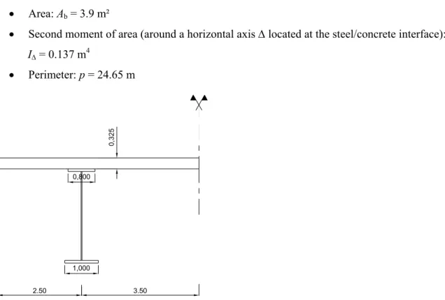
For simplification reasons the actual slab cross-section of a half-deck (see Figure 2-15) is modelled by a rectangular area with the actual width (i.e. 6 m). The height e of this rectangle is calculated so that the actual and modelled sections have the same area. This gives e = 32.5 cm.
The mechanical properties of the whole transverse cross-section of the slab are: Twin-girder bridge
• Area: Ab = 3.9 m²
• Second moment of area (around a horizontal axis Δ located at the steel/concrete interface): IΔ = 0.137 m4 • Perimeter: p = 24.65 m 2.50 3.50 1,000 0,800 0,3 25
Figure 2-14: Modelling the concrete slab for the longitudinal global bending (twin-girder bridge).
Box-girder bridge
• Area: Ab = 21.5 · 0.325 = 6.99 m²
• Second moment of area (around a horizontal axis Δ located at the steel/concrete interface): IΔ = 21.5 · 0.3253 / 12 + Ab · (0.325 / 2)2 = 0.246 m4 • Perimeter : p = (21.5 + 0.325 ) · 2 = 43.65 m 3.250 0 .325 10.750 6.000 4.0 00 1.500
EN 1992-1-1, Table 3.1, Strength and deformation characteristics for concrete EN 1993-1-10 and EN 10164
EN 1993-1-1, 3.2.6, Design values of material coefficients
(1) The material coefficients to be adopted in calculations for the structural steels covered by this Eurocode Part should be taken as follows:
• modulus of elasticity E = 210000 N/mm² • shear modulus
(
)
2 1 E Gν
= ≈ + 81000 N/mm²• Poisson’s ratio in elastic stage ν = 0,3
• coefficient of linear thermal expansion α = 12.10-6 per K (for T ≤ 100 °C)
NOTE: For calculating the structural effects of unequal temperatures in composite concrete-steel structures according to EN 1994 the coefficient of linear thermal expansion is taken as α = 10.10-6 per K.
Similarly, to model the reinforcing bars, each longitudinal reinforcement layer is replaced by a single point-shaped bar with the same area and located in the plane of the main steel web. The reinforcing steel areas are introduced into the numerical model as percentages of the total area of the concrete slab:
Table 2-3: Areas of the steel reinforcement.
ρs (%) top layer 0.48 Mid-span cross-sections bottom layer 0.48 top layer 0.74 Support cross-sections bottom layer 0.48
The centroid of each longitudinal reinforcing steel layer has been assumed to be located at 60 mm away from the closest horizontal face of the concrete slab. This value takes account of the concrete cover and the fact that the transverse reinforcing bars are placed outside the longitudinal reinforcing bars (on the side of the slab free surface).
2.3.2 Material properties
2.3.2.1 Structural steel
Steel grade S355 is considered for this bridge. The subgrades (also called quality) N or NL have been adopted (depending on the plate thickness). The corresponding structural steel mechanical properties are given in EN 10025-3.
Table 2-4: Decrease of fy and fu according to the plate thickness t.
t [mm] ≤ 16 > 16 ≤ 40 > 40 ≤ 63 > 63 ≤ 80 > 80 ≤ 100 > 100 ≤ 150 fy[MPa] 355 345 335 325 315 295 fu[MPa] 470 470 470 470 470 450
The structural steel has a modulus of elasticity Ea = 210 000 MPa (EN 1993-1-1, 3.2.6). In order to
avoid any lamellar tearing, the steel has a though-thickness ductility quality Z15 for the main web (when a transverse bracing is welded to it) according to EN 1993-1-10 and EN 10164.
2.3.2.2 Concrete
Normal concrete C35/45 is used for the reinforced slab. The main mechanical properties are as follows (EN 1992-1-1, 3.1.2, Table 3.1):
• Characteristic compressive cylinder strength at 28 days: fck = 35 MPa
• Mean value of axial tensile strength: fctm = -3.2 MPa
• 5% fractile of the characteristic axial tensile strength: fctk,0.05 = -2.2 MPa
• 95% fractile of the characteristic axial tensile strength: fctk,0.95 = -4.2 MPa
• Mean value of concrete cylinder strength at 28 days: fcm = fck + 8 = 43 MPa
EN 1993-2, 7.3(1), Limitations for stress EN 1993-2, 6.1 and Table 6.2, General
EN 1992-1-1, 2.4.2.4, Partial safety factors for materials EN 1992-1-1, 3.2 and Annex C, Reinforcing steel
EN 1994-2, 3.2(2), Reinforcing steel
(2) For composite structures, the design value of the modulus of elasticity Esmay be taken as
2.3.2.3 Reinforcement
The reinforcing steel bars used in this project are class B high bond bars with a yield strength fsk = 500
MPa (EN 1992-1-1, 3.2 and Annex C).
In EN 1992-1-1 the elasticity modulus of reinforcing steel is Es = 200 000 MPa. However, in order to
simplify the modulus used for the structural steel, EN 1994-2 allows the use of Es = Ea = 210 000 MPa
which will be done in this project (EN 1994-2, 3.2(2)).
2.3.2.4 Partial safety factors for materials
For Ultimate Limit State (ULS) see Table 2-5.
Table 2-5: Partial safety factors for materials (ULS). Design situation γC (concrete) γS (reinforcing steel) γM (structural steel) Persistent Transient 1.5 1.15 γM0 =1.0 γM1 =1.1 γM2 =1.25
Yielding, local instability Resistance of members to instability
Resistance of joints Reference EN 1992-1-1, 2.4.2.4. EN 1993-2, 6.1 and Table 6.1
For Serviceability Limit State (SLS) see Table 2-6.
Table 2-6: Partial safety factors for materials (SLS).
γC (concrete) γS (reinforcing steel) γM,ser (structural steel) 1.0 1.0 1.0 EN 1992-1-1, 2.4.2.4 EN 1993-2, 7.3 (1)
2.3.3 Actions
In order to simplify the calculations, only six different load cases have been defined: 1. Self-weight of the structural steel
2. Self-weight of the reinforced concrete slab (with construction phasing, so in fact 16 load cases for the twin-girder bridges and 45 load cases for the box-girder bridge)
3. Self-weight of the non structural bridge equipments 4. Shrinkage
5. Creep
6. Traffic load LM1
EN 1991-1-1, Table A.4, Construction materials-metals
2.3.3.1 Permanent loads
Distinction is made for permanent loads between the self-weights of the structural steel girders, of reinforced concrete slab and of non-structural equipments.
2.3.3.1.1 Self-weight
The density of the structural steel is taken as equal to 77 kN/m3 (EN 1991-1-1, Table A-4). For
calculation of the internal forces and moments and the stresses for the longitudinal bending global analysis, the self-weights are modelled as follows:
Twin-girder bridge
The self-weight of the in-span located transverse cross girders is modelled by a vertical uniformly distributed load of 1300 N/m applied on each main girder (about 12% of the weight of this main girder). Box-girder bridge
The self-weight of the in-span located transverse frames is modelled by a vertical uniformly distributed load of 8000 N/m for the total width of the bridge (about 12.2 % of the weight of the full box-girder). The density of the reinforced concrete is taken as equal to 25 kN/m3 (EN 1991-1-1, Table A-1).
2.3.3.1.2 Non-structural equipment
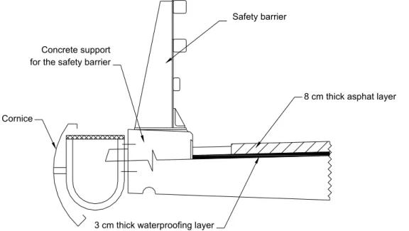
The nominal value of the waterproofing layer is multiplied by ±20% and the nominal value of the asphalt layer by +40% / -20% for all spans (EN 1991-1-1, 5.2.3).
Table 2-7: Loads of the non-structural equipment (twin-girder bridge).
Item Characteristics Maximum multiplier Minimum multiplier qnom
(kN/m) (kN/m) qmax (kN/m)qmin
Waterproofing layer 3 cm thick, 25 kN/m3 1.2 0.8 4.2 5.04 3.36
Asphalt 8 cm thick, 25 kN/m3 1.4 0.8 11 15.4 8.8
Concrete support for
the safety barrier area 0.5 x 0.2 m, 25 kN/m3 1 1 2.5 2.5 2.5
Safety barriers 65 kg/m 1 1 0.638 0.638 0.638
Cornice 25 kg/m 1 1 0.245 0.245 0.245
Total 18.58 23.82 15.54
Table 2-8: Loads of the non-structural equipment (box-girder bridge).
Item Characteristics Maximum multiplier Minimum multiplier qnom
(kN/m) (kN/m) qmax (kN/m)qmin
Waterproofing layer 3 cm thick, 25 kN/m3 1.2 0.8 7.66 9.19 6.13
Asphalt 8 cm thick, 25 kN/m3 1.4 0.8 20.22 28.31 16.18
Safety barrier ground
girder area 0.5 x 0.2 m, 25 kN/m3 1 1 2.50 2.50 2.50
Safety barrier 65 kg/m 1 1 0.64 0.64 0.64
Cornice 25 kg/m 1 1 0.25 0.25 0.25
EN 1991-1-1, 5.2.3, Additional provisions specific for bridges
(1) The upper and lower characteristic values of densities for non structural parts, such as ballast on railway bridges, or fill above buried structures such as culverts, should be taken into account if the material is expected to consolidate, become saturated or otherwise change its properties, during use.
NOTE: Suitable values may be given in the National Annex.
(2) The nominal depth of ballast on railway bridges should be specified. To determine the upper and lower characteristic values of the depth of ballast on railway bridges a deviation from the nominal depth of ±30 % should be taken into account.
NOTE: A suitable value may be given in the National Annex
(3) To determine the upper and lower characteristic values of self-weight of waterproofing, surfacing and other coatings for bridges, where the variability of their thickness may be high, a deviation of the total thickness from the nominal or other specified values should be taken into account. Unless otherwise specified, this deviation should be taken equal to ± 20 % if a post-execution coating is included in the nominal value, and to + 40 % and – 20 % if such a coating is not included.
NOTE: Suitable specifications may be given in the National Annex.
(4) For the self-weight of cables, pipes and service ducts, the upper and lower characteristic values should be taken into account. Unless otherwise specified, a deviation from the mean value of the self-weight of ± 20 % should be taken into account.
NOTE: Suitable specifications may be given in the National Annex. See also EN 1990, 4.1.2(4) (5) For the self-weight of other non structural elements such as:
• hand rails, safety barriers, parapets, kerbs and other bridge funiture, • joints/fasteners,
• void formers,
the characteristic values should be taken equal to the nominal values unless otherwise specified. NOTE: Suitable specifications may be given in the National annex. An allowance for voids filling with water may be made depending on the project.
Figure 2-16 details the non-structural bridge equipment used for the example.
Safety barrier
for the safety barrier
3 cm thick waterproofing layer
8 cm thick asphat layer Cornice
Concrete support
Figure 2-16: Non-structural bridge equipment details.
2.3.3.2 Concrete shrinkage
According to Eurocode 4, three different concrete shrinkage deformations should be considered in the design. In order to simplify the analysis and because thermal shrinkage at early age is part of national choices, it has been decided not to consider it in the calculations. Only autogenous and drying shrinkage deformations (εcs = εca + εcd with notations from EN 1992-1-1, 3.1.4(6)) have been taken into account.
Two values of the total deformation εcs have been then calculated:
Shrinkage deformation for persistent design situation at traffic opening
(for the twin-girder bridge date tini = 80 days, for the box-girder bridge date tini = 170 days)
Table 2-9 summarises the values of autogenous and drying shrinkage deformation for persistent design situation at traffic opening for the twin-girder bridge and the box-girder bridge respectively.
Table 2-9: Shrinkage at traffic opening for the persistent design situation at traffic opening (tini).
twin-girder bridge box-girder bridge
Autogenous
shrinkage 4.88E-05 5.44E-05
Drying
shrinkage 1.36E-05 2.23E-05
Total 6.20E-05 7.67E-05
Shrinkage deformation for persistent design situation at infinite time
Table 2-10 summarises the values of autogenous and drying shrinkage deformation for persistent design situation at infinite time for the twin-girder bridge and the box-girder bridge.
EN 1994-2, 5.4.2.2 (2), Creep and shrinkage
(2) Except for members with both flanges composite, the effects of creep may be taken into account by using modular ratios nL for the concrete. The modular ratios depending on the type of
loading (subscript L) are given by:
nL= n0 (1 +ψL/ϕt) (5.6)
where:
n0 is the modular ratio Ea / Ecm for short-term loading;
Ecm is the secant modulus of elasticity of the concrete for short-term loading according to
EN 1992-1-1, Table 3.1 or Table 11.3.1;
ϕt is the creep coefficient ϕ (t,t0) according to EN 1992-1-1, 3.1.4 or 11.3.3, depending on
the age (t) of concrete at the moment considered and the age (t0 ) at loading;
ψL is the creep multiplier depending on the type of loading, which be taken as 1.1 for
permanent loads, 0.55 for primary and secondary effects of shrinkage and 1.5 for prestressing by imposed deformations
Table 2-10: Shrinkage at infinite time. t=infinite Autogenous shrinkage 6.25E-05 Drying shrinkage 1.77E-04 Total 2.40E-04
Finally for calculating the internal forces and moments for the persistent design situation at traffic opening, a shrinkage deformation of 6.2·10-5 (for the twin-girder-bridge) and 7.67·10-5 (for the
box-girder-bridge) is applied to each slab segment following the concreting order. For the persistent design situation at infinite time, a shrinkage deformation of 2.4·10-4 (for the 2 bridges) is applied to the whole
slab after finishing all concreting phases.
2.3.3.3 Creep – Modular ratios
2.3.3.3.1 Modular ratio for short-term loading
E n E f a 0 0.3 cm cm 210000 22000 10 = = ⎛ ⎞ ⎜ ⎟ ⎝ ⎠ = 6.1625
2.3.3.3.2 Modular ratio for long-term loading
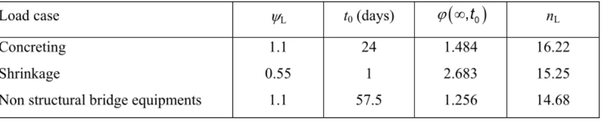
For a given long-term loading L applied to the bridge when the mean age of concrete is equal to t0, the
modular ratio is defined by the following equation for the calculations of the bridge at infinite time (EN 1994-2, 5.4.2.2(2)):
(
)
(
)
nL=n 10 +ψ ϕL ∞,t0
Table 2-11 and Table 2-12 summarise the intermediate values for the calculation of the creep factor
(
,t0)
ϕ ∞ and the modular ratio values nL used in the design of the twin-girder bridge and the box-girder
bridge. See Table 2-1 and Table 2-2 for further details on the ages t0.
Table 2-11: Modular ratio for long-term loading (twin-girder bridge).
Load case ψL t0 (days) ϕ
(
∞,t0)
nLConcreting 1.1 24 1.484 16.22
Shrinkage 0.55 1 2.683 15.25
Non structural bridge equipments 1.1 57.5 1.256 14.68
Table 2-12: Modular ratio for long-term loading (box-girder bridge).
Load case ψL t0 (days) ϕ
(
∞,t0)
nLConcreting 1.1 67.5 1.215 14.40
Shrinkage 0.55 1 2.674 15.23
EN 1991-2, 4.2.3, Divisions of the carriageway into notional lanes
(1) The carriageway width, w, should be measured between kerbs or between the inner limits of vehicle restraint systems, and should not include the distance between fixed vehicle restraint systems or kerbs of a central reservation nor the widths of these vehicle restraint systems.
NOTE: The National Annex may define the minimum value of the height of the kerbs to be taken into account. The recommended minimum value of this height is 100 mm.
(2) The width wl of notional lanes on a carriageway and the greatest possible whole (integer)
number nl of such lanes on this carriageway are defined in Table 4.1.
Table 4.1: Number and width of notional lanes
(3) For variable carriageway widths, the number of notional lanes should be defined in accordance with the principles used for Table 4.1.
NOTE: For example, the number of notional lanes will be: • 1 where w < 5,4 m
• 2 where 5,4 ≤ w < 9 m • 3 where 9 m ≤ w < 12 m, etc.
(4) Where the carriageway on a bridge deck is physically divided into two parts separated by a central reservation, then:
(a) each part, including all hard shoulders or strips, should be separately divided into notional lanes if the parts are separated by a permanent road restraint system ;
(b) the whole carriageway, central reservation included, should be divided into notional lanes if the parts are separated by a temporary road restraint system.
NOTE: The rules given in 4.2.3(4) may be adjusted for the individual project, allowing for envisaged future modifications of the traffic lanes on the deck, e.g. for repair.