BIOREFINE
Recycling inorganic chemicals from agro- and bio-industrial
waste streams
Project/Contract number: 320J - Biorefine
Document number: BIOREFINE – WP2 – A6 – P1, 2, 3, 5, 8 – D
Techniques for nutrient recovery from manure and slurry
Date: 13/05/2015Start date of project: 1 May 2011 Duration: 56 months
Authors: M. A. Camargo-Valero, L. De Clercq, F. Delvigne, A. Haumont, V. Lebuf, E. Meers, E. Michels, U. Raesfeld, D. R. Ramirez-Sosa, A. B. Ross, O. Schoumans, E. Snauwaert, C. Tarayre, N. Tarayre, E. Vandaele, G. Velthof, P. T. Williams
Authors’ Institution: AILE, Alterra, Gembloux Agro-Bio Tech, Ghent University, University of Leeds, VCM, Vlaco
Project funded by the European Regional Development Fund through INTERREG IV B Dissemination Level
PU Public x
PP Restricted to other programme participants (including the Commission Services)
RE Restricted to a group specified by the consortium (including the Commission Services) CO Confidential, only for members of the consortium (including the Commission Services)
BIOREFINE – WP2 – A6 – P1, 2, 3, 8 – D 2
Table of contents
Table of contents ... 2
1 Glossary ... 3
2 Introduction ... 5
3 State-of-the-art techniques for nutrient recovery from manure ... 5
3.1 Drying of manure with air from the stable ... 6
3.2 Composting (biothermal drying) of solid manure... 10
3.3 Liming of manure ... 13
3.4 Biogas production from manure/slurry and CHP plant (example 1) ... 14
3.5 Biogas production from manure/slurry and CHP plant (example 2) ... 15
3.6 Biogas production from slurry and CHP plant (example 3) ... 16
3.7 Ammonia stripping and scrubbing (example 1) ... 19
3.8 Ammonia stripping and scrubbing (example 2) ... 20
3.9 Filtration techniques – Reverse osmosis ... 23
3.10 Separation of pig manure under slats: the V-shaped scraping ... 30
4 Techniques for nutrient recovery from manure in development... 31
4.1 Phosphorus precipitation ... 31
4.2 Pyrolysis - Biochar production from solid manure ... 38
5 List of useful contacts ... 40
BIOREFINE – WP2 – A6 – P1, 2, 3, 8 – D 3
1 Glossary
AD: Anaerobic Digestion ADG: Average Daily Gain CEC: Cation Exchange Capacity CHP: Combined Heat and Power C/N : Carbon-to-Nitrogen ratio DAF: Dissolved Air Flotation DM: Dry Matter
EC: Electric conductivity FCR: Feed Conversion Rate GCL: Geo-synthetic Clay Liner GRP: Glass Reinforced Plastic g/l: Gram per litre
H2S: Hydrogen sulphide
K: Potassium
kg/l: Kilogram per litre kW: Kilowatt
kW/d: Kilowatt per day kWel: Kilowatt electric kWh: Kilowatt hour kWth: Kilowatt thermal
MAP: Magnesium Ammonium Phosphate MDPE: Medium-Density PolyEthylene MF: Microfiltration
mg/l: Milligram per litre MW: Molecular Weight (1) MW: Megawatt (2)
m³: Cubic metre
m³/y: Cubic metre per year µm: Micrometre
BIOREFINE – WP2 – A6 – P1, 2, 3, 8 – D 4 N: Nitrogen
N-P: Nitrogen-to-Phosphorus ratio NAR: Nijhuis Ammonia Recovery NH3: Ammonia
NH4-N, NH4+-N: Ammoniacal nitrogen
NO3-N, NO3--N: Nitrogen in the form of nitrate
NPK: Nitrogen, Phosphorus, Potassium Ntot: Total Nitrogen
NWE: North-West Europe OM: Organic Matter P: Phosphorus ppm: part per million RO: Reverse Osmosis sec: Second
To: Temperature
t: Ton
t/d: Ton per day t/y: Ton per year UF: Ultrafiltration
BIOREFINE – WP2 – A6 – P1, 2, 3, 8 – D 5
2 Introduction
In many cases, manure is the main source of fertiliser for farmers and has been closing the nutrient cycling for a long time. It is a valuable source of nutrients for crops. However, in regions with intensive livestock farming systems, the amount of nutrients exceeds the nutrient requirements of crops. The surplus of nitrogen (N) and phosphorus (P) results in high emissions of N and P to groundwater, surface water, and the atmosphere in these regions (Velthof et al., 2014). On the other hand, the global demand for minerals is high and several minerals such as phosphorus (P) and potassium (K), which are nowadays being extracted through mining, are becoming scarce at a quick pace. As a consequence, nutrient removal and recovery from manure has received a lot of attention in regions with intensive livestock farming such as The Netherlands and Flanders (Schoumans et al., 2015).
Since 1991, the European Nitrates Directive has been implemented to improve water quality, forcing member states to define an action plan applicable to vulnerable zones. In Flanders, designated entirely as vulnerable zone, manure processing has been developed since the 90’s, in order to remove nitrogen or export nutrients in excess to less nutrient dense areas.
Nowadays, with the volatile prices of fossil-based fertilisers and lower phosphorus and potassium reserves, farmers’ and fertiliser producers’ concern is moving from manure processing to more sophisticated nutrient recovery techniques, though this development is still limited. BIOREFINE is a project funded by the Interreg IVB NWE program which aims at stimulating nutrient recovery by providing innovative strategies, both from economic and environmental points of view, and stimulate the marketing of end-products. This report provides a global non-limitative overview of full-scale techniques for nutrient recovery from manure and techniques which are still being developed.
3 State-of-the-art techniques for nutrient recovery from manure
An overview of the main pathways of nutrient recovery from animal manure is shown in Figure 1. Nowadays, the most common way to process pig slurry in Flanders consists in treating the thin fraction biologically and drying (and pelletizing) or composting the dried solid fraction before exporting the products to regions with arable land in need of organic fertilisers (Schoumans et al., 2015). It is more profitable to turn the components of manure into valuable products (Schoumans et al., 2015).BIOREFINE – WP2 – A6 – P1, 2, 3, 8 – D 6
Figure 1: Overview of the main options to recover nutrients from manure.
Source: Schoumans O. et al., (2015)
The different techniques are applied on different scales. It must be kept in mind that some of them are still in the development stage.
3.1 Drying of manure with air from the stable
The process of manure drying using air from the stable is relatively easy for solid types of manure, such as poultry manure or pig manure after mechanical separation. This technique is consequently widely applied in the poultry industry to reduce the manure volume and stabilize the end-product, but it is also applicable to the thick fraction of pig manure or pig slurry itself. Various drying systems, e.g. ventilation ducts and drying tunnels, perforated floors or belts and the “Seconov” system, etc., are available on the market and are in operation in poultry buildings. All these techniques use the air of the building, which has a temperature of approximately 20°C.
BIOREFINE – WP2 – A6 – P1, 2, 3, 8 – D 7
3.1.1 Description of the techniques
Pre-drying systems with air ducts
Poultry droppings fall on conveyers installed under hens cages. Each battery has a ventilation duct in a central position. The duct has a slot for propelling the hot air at a height of 15 cm above the belt. The hot air is drawn through the building extractors and sent to an air exchanger, where the farmer has the opportunity to introduce more or less fresh air. The battery belts are started by the farmer every morning. The droppings generally stay under the cages 6 to 7 days before being exported to the storage room, where they can be composted or removed for exportation.
Drying tunnels
The droppings fall on conveyers installed under the hens cages, while a cross conveyor transports the droppings to the drying tunnel. The drying tunnel is composed of several stages of perforated belts, on which the droppings are spread. Ventilators pull the air through the plates, thus drying the droppings. The belts progress every day at a specific speed, so that the droppings are discharged when the thickness is approximately 75 % DM. The process scheme is shown in Figure 2.
Figure 2: Drying tunnels.
BIOREFINE – WP2 – A6 – P1, 2, 3, 8 – D 8
Perforated belt or floor
At poultry farms with laying hens, the manure is removed from the batteries through a transport belt system and transferred to a drying system. The manure ends up on a perforated belt or floor through which hot air is blown by a fan causing an exchange of heat and moisture: the manure product is dried and the moisture is removed with the air (Lemmens et al., 2007). Additionally, a drying drum can be used for further drying (Melse et al., 2004). A major feature of the drying processes using stable air is the reduced ammonia emission in the stables.
The dried manure can either be stored in a barn or taken straight to the end-user for further processing. During gradual storage in the barn, the product spontaneously turns into compost at temperatures up to 70°C. In this way, the manure generates over 60% dry matter (Lemmens et al., 2007). The dried product can also be pressed to pellets and hygienized in a central location. After the pressing process, the pellets (at a 70°C temperature) undergo a heat treatment (the temperature of the outgoing air is kept at 90°C for 30 minutes) (Melse et al., 2004).
The technique is more difficult to use with pig slurry since it is too fluid to form a bed through which air can circulate. The pig slurry can first be sorted and the thick fraction can be treated as described above. Pig slurry drying can also be achieved by recirculating the dried fraction. This end-product can be used as a carrier for raw manure slurry (Figure 3). Alternatively, the separated solid fraction can also be used as a carrying material (Lemmens et al., 2007).
Figure 3: Schematic overview of the manure drying process using air from the stable and a perforated belt or floor.
Source: modified from Lemmens B. et al., (2007)
The quantity of dried end-product with a dry matter content of 80-85% is mixed together with raw manure with a dry matter content of 5-10% so as to get a semi-solid product with a dry matter content of approximately 30-50%. This product is dried once again on a drying belt, so that a final product with a dry matter content of 80-85% is obtained (Lemmens et al., 2007; Melse et al., 2004).
BIOREFINE – WP2 – A6 – P1, 2, 3, 8 – D 9 Part of this final product is recirculated back to the drying system while the rest goes to final storage. The used air is led to a chemical scrubber and the scrubber water (ammonium sulphate) can be used as N-S-fertiliser (Melse et al., 2004).
The “Seconov” process
The droppings come from the conveyor belt and are then carried inside the drying room to the distributing crab by loading the conveyor (similar to the perforated belt or floor system). This device spreads the product evenly all over the drying cell. A ventilation system then blows the air drawn from the barn through the perforated platform for 24 hours. Afterwards, the droppings are transferred to the bottom of the drying device. From there, it is gathered by an auger that carries it out towards the storage location, where they can be pelletized.
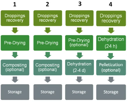
3.1.2 Unit operations
The unit operations of the different systems are shown in Figure 4.
Figure 4: Unit operations of the treatment of poultry manure – 1. Pre-Drying with perforated belt or floor, 2. Pre-drying with air duct, 3. Dehydration with tunnel, 4. Seconov drying system.
Source: AILE
BIOREFINE – WP2 – A6 – P1, 2, 3, 8 – D 10
3.1.3 End-product
Depending on the system, the hygienizing effect of the drying stage is more or less effective. Before composting can start spontaneously up to temperatures exceeding 70°C, the poultry manure can be pre-dried in an air duct or dried in a tunnel before a two-month storage period. In this way, the manure produces over 60% of dry matter (Lemmens et al., 2007). Drying is more efficient with the “Seconov” system (70 % DM in 24h) as used in France, but the end-product is not completely hygienized, according to the French standards NFU 44-051 (Derel R. et al., 2008). The dried manure can be stored in a barn, carried away for further processing or delivered as it is to the end-user. The dried product can also be pressed to pellets to facilitate transport and hygienized in a central location to become fit for export. After the pressing process, the pellets (at a 70°C temperature) undergo a heat treatment (the temperature of the outgoing air is kept at 90°C for 30 minutes) (Melse et al., 2004). An additional benefit is that poultry manure and droppings drying improves air quality for both animals and farmers.
3.1.4 Useful contact(s) for further information
AILE (France)
Email address: [email protected]
University of Ghent (Belgium)
Email addresses: [email protected], [email protected], [email protected]
VCM (Belgium)
Email address: [email protected]
3.2 Composting (biothermal drying) of solid manure 3.2.1 Description of the technique
Composting the solid fraction of pig manure is frequently carried out in Flanders in order to pasteurize manure at 70°C for 1 hour without using external heat. Composting (self-heating) of the product at temperatures exceeding 70°C is only possible if a maximum of 30 wt% of solid fraction of pig manure is used. This can be then combined with the solid fraction of cattle slurry, cattle manure with straw, horse manure or poultry manure to obtain enough structure and an optimal C/N ratio. Some composting sites also add vegetal biomass or vegetable, fruit and garden (VFG) waste or green waste compost. In large installations, the volatilized ammonia is captured by air treatment with sulphuric acid in an acid air washer (Figure 5). Most of the process occurs in a closed shed consisting of several tunnels which can be closed off and aerated separately. Sometimes it is also done inside
BIOREFINE – WP2 – A6 – P1, 2, 3, 8 – D 11 an aerated drum. In some installations the material is placed in rows on the floor and is turned over manually. It is a short, very intensive composting process that takes only a few days.
Figure 5: Schematic overview of the composting process of the solid manure fraction.
Source: modified from Melse R.W. et al., (2004)
3.2.2 End-product
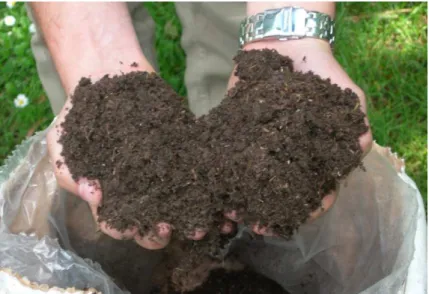
The end-product is an organic fertiliser suitable for export and use in agriculture. Depending on the wishes of the customer, potassium or lime can be added, by dosing e.g. Haspargit (from the production of citric acid) or precipitated calcium carbonate (from the sugar beet industry). The mineralisation rate of the nitrogen present in the product varies from 40 to 50%. The potassium and phosphorus present in the products are available for plants in big quantities: 60 to 70% of the phosphorus and 100% of the potassium are available at once. Figure 6 shows a picture of composted manure.
BIOREFINE – WP2 – A6 – P1, 2, 3, 8 – D 12
Figure 6: Composted manure.
Source: VCM
The average composition of the end-products coming from Flemish co-composting sites (co-composting of animal manure and biodegradable wastes) is given in Table 1. The ammonia (NH3)
that is stripped during the composting process is washed with sulphuric acid (H2SO4) in the acid air
washer, which results in ammonium sulphate ((NH4)2SO4), an effective mineral nitrogen-sulphur
fertiliser.
Table 1: Average composition of the end-products available from Flemish co-composting sites.
Dry matter 47.1 %FM Organic matter 29.5 %FM EC (1/5) 7465.0 µS/cm pH (H2O) 8.4 - Chlorides 1975.0 mg/L Density 0.5 kg/L Total N 1.5 %FM NH4-N 2525.0 mg/L NO3-N 10.0 mg/L C/N 11.5 - Total P2O5 1.62 %FM Total K2O 1.31 %FM Total CaO 3.42 %FM Total MgO 0.70 %FM Impurities > 2mm 0.02 %FM Stones > 5mm 0.10 %FM Weed seeds 0 #/L Source: VLACO
BIOREFINE – WP2 – A6 – P1, 2, 3, 8 – D 13
3.2.3 Useful contact(s) for further information
University of Ghent (Belgium)
Email addresses: [email protected], [email protected], [email protected]
VCM (Belgium)
Email address: [email protected]
3.3 Liming of manure
3.3.1 Description of the technique
The liming process of the solid manure fraction is an exothermal process, with a significant increase in temperature. Under optimal conditions, a temperature of up to 70°C can be reached and maintained for at least one hour, which is a minimum requirement for the marketability of these products according to the Animal By-products Regulation (EC No. 1069/2009). A mixture of solid fraction of pig manure and poultry manure is added with CaO.MgO. Due to temperature rise and pH increase, ammonia is stripped from the product and must be captured with an acid air washer. Other volatile odour compounds must be captured with a bio-filter. The bio-filter consists of a large open container filled with wood from tree roots and is sprinkled to improve bacterial growth.
The liming treatment increases the total dry matter content by 10-15% and significantly reduces the odour of the raw material (poultry and pig manure). To match the specifications expected by the customer, mineral nitrogen or potassium fertiliser, either liquid or solid, can be added.
3.3.2 End-product
The end-product is a stabilised organo-mineral fertiliser, with a high pH and Ca content. The exact NPK composition of the product depends on the client’s wishes. During the storage of the product in heaps, a crust appears, acts as a perfect isolation means against rain and nutrient leaching and prevents odours from developing. In addition, significant mass losses during storage are avoided. Due to the high pH level, it is a pathogen-free product. It can be used to improve the pH of certain soils and compensate for magnesium lacks. At the same time, it contributes to adding significant amounts of NPK and organic matter.
The mineralization rate of the nitrogen present in the product is much higher than in a regular compost. This means that nitrogen is available for the plant in the early stages of the growing season, when the plant needs it most. The higher mineralization rate is due to the fact that liming results in a more porous, aerated soil, and has a neutralising effect on the protons released during nitrification. Furthermore, the available sulphur and trace elements in the product are easily available for plants. The product increases the permeability of the soil and prevents compaction. This results in better root growth, and significantly improves microbial life in soils. The end-product from the acid air washer is ammonium sulphate, a valuable substitute for mineral nitrogen fertilisers.
BIOREFINE – WP2 – A6 – P1, 2, 3, 8 – D 14
3.3.3 Useful contact(s) for further information
University of Ghent (Belgium)
Email addresses: [email protected], [email protected], [email protected]
VCM (Belgium)
Email address: [email protected]
3.4 Biogas production from manure/slurry and CHP plant (example 1) 3.4.1 General description
Lodge Farm has 650 cross-bred dairy cows, selling milk to a Welsh organic milk cooperative. The Lodge Farm digester has been successfully digesting cattle manure and slurry, as well as ashes and wood chips. The trouble with ashes is that they tend to fall out of suspension even when stirred at a high speed, which causes sediments in the digester. The 1,100 m3 digester operates in mesophilic
conditions. It consists of an insulated steel glass coated tank and internal heat exchangers and its contents are mixed by gas. The Biogas produced is used in a 88 kW CHP unit for the production of electricity and heat for the digester and also for export to the grid.
The digester is normally loaded with 30 t/d of cattle manure/slurry mixed with ash and woodchip and 3 t/d chicken muck (Bywater, 2011).
3.4.2 Unit operations
Anaerobic digestion
Feedstocks get into the digester without any prior treatment. Mixer waggons load chicken muck and mix it together with slurry. Liquid slurry is fed directly into the anaerobic digester from a holding tank. To reach mesophilic conditions, the digester is heated at 40 °C with heat coming from internal heat exchangers and from the CHP unit. Slurry, manure and chicken muck are pumped into the digester for a continuous feeding while 5 % of dry matter of the digester volume are unloaded over a belt press separator, the retention time being 28 days. The resulting liquor flows into a lagoon and the cake is put into a bunker. The digester is made of steel and has 14.66 m in diameter and 7 m in height. The mixing in the tank is done by a sequential, unconfined, 6-port rotary valve gas mixing system in order to prevent crust forming, since the digestate is not intended to be completely mixed. Gas is scrubbed by air injection into the top of the digester. Due to slow agitation, the resulting biogas has a low concentration in H2S (about 100-200 ppm).
De-gritting system
Every two weeks around 22 % of dry matter are removed from the digester through the de-gritting system. The mass removed from the bottom of the digester is around 14-15 tons.
BIOREFINE – WP2 – A6 – P1, 2, 3, 8 – D 15
Biogas combustion in the CHP plant
Biogas is stored in a 3.5 m3-insulated bell over water gas holder and is burnt in an 88 kW CHP, whose
heat is used inside the digester.
Solid/liquid separation
The digestate is separated from the liquid phase. The cake is spread over arable land owing to its higher content of P and N while the liquor is spilt over grassland. All the digestate is consumed on-site, enabling the farm to target nutrient applications more effectively. The digestate is applied using a spike aerator with a driller bar behind it to reach a depth of 5-6” for more effective soil penetration.
Biogas surplus use
Biogas is used in a Beaver Power/Perkins Quantum 88 kW CHP. Biogas production is around 50 m3 per hour and is scrubbed mainly by air injection, maintaining an H2S level varying from 100 to 200
ppm. There is an auxiliary gas boiler to allow excess gas to be burned and to provide heat for the digester when the CHP is down for maintenance.
3.4.3 Useful contact(s) for further information
University of Leeds (United Kingdom)
Email addresses: [email protected], [email protected], [email protected]
3.5 Biogas production from manure/slurry and CHP plant (example 2) 3.5.1 General description
Bank farm has been operating four anaerobic digesters to treat farm residues for energy and self-sufficient fertilising and to export electricity as well. The farm digester also needs substrates costing about £ 20,000 per year.
The first digester has a capacity of 265 m3, consists of a steel tank with an insulated GRP roof and
internal heat exchangers and has its contents mixed by using gas. The other three 175 m3 digesters consist of three-stage concrete digester tanks with insulated GRP roof and pasteuriser, work under mesophilic conditions and also have their contents mixed with gas.
Anaerobic digesters produce around 124 kW CHP and heating for 2 houses. Feedstock is currently slurry and manure from 130 dairy cows and 150 oxen for slaughter, which produces about 2,500 t manure/y, 150 t of chicken muck/y, 30 t of waste silage/y, used animal bedding, sugar beets, potatoes and grass grown on farm.
The system for the digesters is flexible and can accept diverse feedstocks like poultry manure, farm yard manure, silage effluent, waste silage, discarded milk, green waste, potatoes, sugar beets or any other organic substrates available (Bywater, 2011).
BIOREFINE – WP2 – A6 – P1, 2, 3, 8 – D 16
3.5.2 Unit operations
Mixing step
Slurry and manure are scraped directly into an input pit consisting of a big hopper with an auger chopper which can mix 20-30 t of waste at a time. The thick mixture is then automatically fed overnight at hourly intervals into the digester running on a timer. The digester uses gas to mix via a port rotary valve and heat with two internal heat exchangers. The output is moved out with a 5” auger to a belt press separator.
Anaerobic digestion
Digester 2 consists of a rectangular 3 stage tank with measures of 3.5 m x 10 m x 5.3 m in depth and has insulated fibreglass roofs. The mixing inside the tanks is done by six port rotary valves and the heating is provided by 3 internal heat exchangers. The digester is capable of coping with 24 t per day. The digesters are heated between 38 °C and 42 °C.
Solid/liquid separation
After AD process, liquid and solids are separated by a belt press. About 3,000 t/y of digestate is produced by all the digesters, consisting of about 20 % fibre, 75 % liquid and 5 % gas. All the digestate is separated into both liquid and solid fractions. The fibre is scattered over the farmyard with a muck spreader.
Liquor degasification
Separated liquor goes into a covered post-store, where gas is removed by using air injection so as to release some gases that could be trapped. The post-store is covered by a large insulated fiberglass roof.
Biogas combustion in the CHP plant
The biogas produced is currently recovered from a CHP generating 80 kWth. The CHP produces about 70 MW per month, approximately 2,500 kW/d or 90-100 kWh.
3.5.3 Useful contact(s) for further information
University of Leeds (United Kingdom)
Email addresses: [email protected], [email protected], [email protected]
3.6 Biogas production from slurry and CHP plant (example 3) 3.6.1 General description
Singleton Birch is a Lincolnshire based lime business with nearly 200 years of experience in one of the oldest industrial processes: quarrying. As part of a commitment to control energy costs, lower
BIOREFINE – WP2 – A6 – P1, 2, 3, 8 – D 17 carbon footprint and reduce reliance on grid electricity, the company uses one of the latest and greenest agricultural technologies: electricity production from biogas.
Another positive part of the project has been the cooperation with local farmers who provide the agricultural input material for the plant, which includes poultry manure, maize, silage, vegetable waste, potato peelings and sugar beet silage. All of these are fed into a 6 m high and 25 m wide concrete tank via a PlanET Vario with additional loosening auger (muck and grass version). In addition to this, grass cuttings from the nearby Humberside Airport are regularly added to the feeder. Together with water, the material is digested and the resulting biogas is used to fuel six 250 kWel CHP units.
The biogas is desulphurised by the PlanET eco® cover, a close-meshed fabric, which is installed beneath the double membrane roof (PlanET Flexstore). In the final step of the process, the digestate is sorted to reduce the required storage capacity and make transportation easier. Local farmers use the substrate as a fertiliser, which is spread on their fields. With substrate requirements matching farming crop rotation, it is a win-win scenario for all and the basis for long-term cooperation between the industrial and agricultural sectors (PlanET Biogas UK Ltd, 2013).
The outputs of the anaerobic process in Singleton Birch plant are: - biogas – 2,308 m3/y,
- electrical energy and heat energy as a result of the burning of the biogas, - processed digestate – 13,867 m3 of which:
o 3,000 m3 which are dried to get 2,730 t water vapour and 270 t dried digestate (fertiliser)
o 10,867 m3 to be separated: 869 t solid fraction, 9,998 t liquid fraction.
3.6.2 Unit operations
The main feedstock used in the anaerobic digestion process in Singleton Birch includes agricultural slurries, manures and crops as described below:
- Maize – 5,175 t - Pig Manure – 5,000 t - Pig Slurry – 3,500 t - Energy Beet – 2,500 t - Total – 16,175 t per year
The process consists of several steps.
Pumping, storage and handling of feedstock
BIOREFINE – WP2 – A6 – P1, 2, 3, 8 – D 18
Anaerobic digestion
The system is composed of 2 digesters (25 m diameter, 6 m height, 2,945 m³ volume, wall and base heating, PlanET eco® cover +, PlanET Flexstore XL). The mixing system is a PlanET eco® paddle (3 PlanET eco® mix; feature - PlanET Cutter, Separator).
Biogas combustion in the CHP plant
The CHP unit is composed of a container unit (13 m long, 3 m wide and 3 m high).
Drying, storage and handling of digestate
The dry feeding system is a PlanET MultiRotor Vario of 96 m³. The lagoon for feedstock storage has a capacity of 7,400 m3 with a 1 mm MDPE primary protection liner, with a built-in leak detection
system. Another protection layer consists of a reinforced Geo-synthetic Clay Liner (GCL). This element consists of a layer of natural Sodium Bentonite between a woven and a non-woven geotextile which are needle-punched together (ADBA, 2014, Robinson, 2014).
The process scheme is shown in Figure 7.
3.6.3 Process scheme
Figure 7: Anaerobic Digestion Process of manure/slurry combined with CHP plant.
BIOREFINE – WP2 – A6 – P1, 2, 3, 8 – D 19
3.6.4 Useful contact(s) for further information
University of Leeds (United Kingdom)
Email addresses: [email protected], [email protected], [email protected]
3.7 Ammonia stripping and scrubbing (example 1) 3.7.1 Description of the technique
The ammonia stripping and scrubbing technique can be applied to a nitrogen rich waste stream, such as manure slurry or the liquid fraction of manure or digestate.
As shown in Figure 8, ammonia is removed (stripped) by blowing air or steam through the manure slurry in a tray or tower. The liquid stream flows in at the top while the air gets in at the bottom. In this way, ammonia passes from the liquid to the gaseous phase using a counter-current system. The strip gas, charged with ammonia, is then captured and the ammonia is removed by washing it with a strong acidic solution, such as sulphuric acid, in the scrubbing system. The ammonia-free air can be reused in the stripping tower. For optimal removal, the pH of the influent is often raised to 10 and the temperature increased to 70°C to shift the NH4+/NH3 equilibrium towards free ammonia
(Lemmens et al., 2007).
Figure 8: Schematic overview of the stripping and scrubbing technique to recover ammonia from manure.
Source: modified from Melse R.W. et al., (2004)
3.7.2 End-product
The reaction of ammonia (NH3) with sulphuric acid (H2SO4) results in ammonium sulphate
BIOREFINE – WP2 – A6 – P1, 2, 3, 8 – D 20 has been sufficiently pretreated, a removal efficiency of >90% nitrogen can be reached (Lemmens et al., 2007).
3.7.3 Stage of development
The ammonia stripping and scrubbing technique is already widespread, but not so frequently used for manure (and digestate) treatment (Lebuf et al., 2013). Within the project, the ammonia recovery technique applied to the liquid fraction of digestate is investigated on pilot scale by Waterleau and described in the report ‘Techniques for nutrient recovery from digestate derivatives’.
3.7.4 Useful contact(s) for further information
University of Ghent (Belgium)
Email addresses: [email protected], [email protected], [email protected]
VCM (Belgium)
Email address: [email protected]
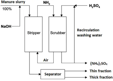
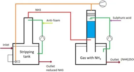
3.8 Ammonia stripping and scrubbing (example 2) 3.8.1 General description
Nijhuis industry has developed the Nijhuis Ammonia Recovery unit (NAR), which removes NH4+ from
anaerobic digestion liquors. This technique is based on stripping of NH3 from liquid. The carrier gas is
washed with sulphuric acid to form ammonium sulphate, which is accepted as a fertiliser and can be used for agricultural purposes. The process is run at approximately 80°C and pH 8.5 to facilitate the separation of NH3. Residual ammonia is oxidized by the existing biological treatment system. An
ammonium removal and recovery system would not only prevent this inhibition and increase biogas production but also recover the valuable nutrient nitrogen.
Nijhuis Water Technology developed an ammonia stripper (NAR) to recover nitrogen from concentrated streams. Figure 9 shows a diagram of the ammonia stripping process (Delgorge, 2013).
Figure 12 provides another overview of the process.
The substrate in the stripping tank is adjusted to optimal conditions, 80 °C and pH 8–9, to remove the ammonia. Gas is circulated through the liquor in the stripping tank and the contact column, and transports ammonia from the stripper tank to the scrubber column. Fresh air is pumped into the circulation gas flow which increases the pH in the stripper tank and improves transport from ammonia into the gas phase.
Heating takes place in two steps:
- Heat exchanging from effluent to influent in order to recover energy. - Final heating with steam or other available heat source.
BIOREFINE – WP2 – A6 – P1, 2, 3, 8 – D 21 The gas containing ammonia is washed in a scrubber column with sulphuric acid. Ammonia and sulphuric acid are turned into ammonium sulphate ((NH4)2SO4) in solution in accordance with the
equation below.
Eq. 1: Production of ammonium sulphate from slurry
2NH3 + 2H + + SO
4 2-
2NH4+ + SO42- (dissolved (NH4)2SO4)
Carrier gas free from ammonia is reused in the stripping tank. The solution containing ammonium sulphate can be used as a liquid fertiliser in agriculture (Delgorge, 2013).
3.8.2 Unit operations
For ammonia recovery, two configurations are proposed.
Ammonium removal during hydrolysis
With this configuration (see Figure 10), stripping and chemical/physical hydrolysis is carried out in one tank at the same time. The stripper tank is operated at high temperature (70-90 °C). Part of the digestate can be recycled to the stripper tank to dilute the feed and to enhance the removal efficiency. The removal of ammonia prior to anaerobic digestion has the advantage of preventing toxicity in the subsequent process as well as pasteurization of the slurry in the stripper tank.
Ammonia removal after anaerobic digestion
In contrast with the first conformation, the stripper tank in the second configuration is located after the digester and also has a high temperature (70–90 °C). The digestate can also be recycled for dilution of the feed and to enhance the removal efficiency. This configuration is shown in Figure 11. Considering that NH3-N/total-N ratio for raw manure is approximately 0.5 and 0.7-0.8 for the
digestate, the stripper efficiency after anaerobic digestion is higher, although raw slurry can have a high N load (also depending on recycle flow) that can lead to a toxic level in the digester (Delgorge, 2013).
BIOREFINE – WP2 – A6 – P1, 2, 3, 8 – D 22
3.8.3 Process scheme
Figure 9: Ammonia stripper developed by Nijhuis Water Technology.
Source: Nijhuis Water Technology, (year not specified)
Figure 10: Ammonia recovery during hydrolysis.
Source: Delgorge F.H., (2013)
Figure 11: Ammonia recovery system after anaerobic digestion.
BIOREFINE – WP2 – A6 – P1, 2, 3, 8 – D 23
Figure 12: Nijhuis Ammonia Recovery flow diagram in Bernard Matthews’ farms.
Source: Nijhuis Water Technology, (year not specified)
3.8.4 Useful contact(s) for further information
Nijhuis Water Technology (The Netherlands)
Email address: see the website www.nijhuisindustries.com/nijhuis-water-technology/
University of Leeds (United Kingdom)
Email addresses: [email protected], [email protected], [email protected]
3.9 Filtration techniques – Reverse osmosis
Separation of livestock slurry in a solid and liquid fraction followed by reverse osmosis of the liquid fraction is a technique that was reported before (Ledda et al., Thörneby et al., 1999). The reverse osmosis decreases the quantity of water in the liquid fraction. This process results in a concentrated N-potassium (K) solution (“mineral concentrate”) in which most of the N is present as ammonium (NH4+). The solid fraction is rich in organic matter and P, and can be used as a soil conditioner. The
water removed by reverse osmosis has low concentrations of nutrients and can be discharged into sewers or surface water (Hoeksma et al., 2011, 2012). RO lowers the slurry volume by removing water and therefore decreases transport costs.
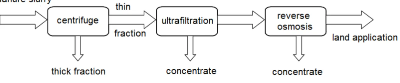
3.9.1 Description of the technique
The slurry is first sorted using a centrifuge (or other type of mechanical separator) (Figure 13). The solid fraction can be further processed by drying, composting, etc. (see above). The thin fraction is treated by ultrafiltration or dissolved air flotation (DAF). During DAF, small air bubbles are blown through the liquid fraction, pushing suspended solids to the surface where they form a crust which can be scraped off (Lebuf et al., 2013). The effluent (from DAF) or permeate (from UF) containing
BIOREFINE – WP2 – A6 – P1, 2, 3, 8 – D 24 only dissolved salts and small organic molecules is further treated by reverse osmosis to a coloured clear fluid that can be applied on the crop land, reused on the farm (e.g. to clean the stables or trucks) or discharged (Melse et al., 2004). The dissolved salts, also called mineral concentrates, remain in the concentrate obtained after reverse osmosis (Velthof, 2011). A more detailed description of the unit operations can be found below.
Figure 13: Schematic overview of the filtration techniques applied to manure slurry. Instead of ultrafiltration, also microfiltration, dissolved air flotation or other types of filters can be used as a pre-treatment for reverse osmosis.
Source: modified from Melse R.W. et al., (2004)
BIOREFINE – WP2 – A6 – P1, 2, 3, 8 – D 25
Figure 14: Picture of a reverse osmosis installation.
Source: VCM
3.9.2 Unit operations
Mechanical separation
In the first step, the slurry is sorted. The separation must be highly effective because the effluent that goes through the reverse osmosis unit should be as clean as possible to avoid scaling and fouling. Examples of mechanical separation are centrifuge, but belt press and screw press can be used as well.
A decanter centrifuge can be used for separation based on a centrifugal force. In a review from Hjorth et al. (2010), the mean separation index of dry matter by a decanter centrifuge was 61 ± 16%. The separation index was defined as the mass of a compound in the solid fraction compared to the mass of a compound in the original raw slurry.
A belt press can be used to filter out solids from liquids. The liquid is drained by gravity from solids in the separator (Hjorth et al., 2010). The filter cake is continuously removed as the belt rotates. The liquid flows through the screen and is drained off. In the same review from Hjorth et al. (2010), the mean separation index of dry matter by a drainage using a belt press was 44 ± 27%.
A screw press or press auger separator can be used for pressurized filtration. The effluent is taken into a cylindrical screen with a screw. The liquid which flows through the screen is collected. The mean separation index of dry matter is 37 ± 18% (Hjorth et al., 2010).
Treatment of effluent
BIOREFINE – WP2 – A6 – P1, 2, 3, 8 – D 26 Ultrafiltration is a membrane filtration technique in which pressure (typically 2-10 bar) leads to a separation through a semi-permeable membrane (2 nm – 0.1 μm). Ultrafiltration concentrates suspended solids and solutes of high molecular weight. The permeate contains low-molecular-weight organic solutes and salts.
After mechanical separation, the liquid fraction can also be treated by dissolved air flotation (DAF). Small air bubbles are pumped through the liquid from the bottom. Organic particles will be driven to the upper part and will form a layer with organic material on the liquid. This layer can be removed by scraping or membrane filtration (10 μm).
In most suspensions, colloidal particles will not aggregate because the particles have negative charges and repel each other (Hjorth et al., 2010). To enhance the removal of these particles, coagulating and flocculating chemicals can be added to the liquid. These chemicals cause colloids and other suspended particles in liquids to aggregate. In most cases, aluminium and iron salts are used to neutralize negative charges (coagulation). The positively charged metal salts (multivalent cations) interact with the negatively charged organic particles, which causes these too aggregate. A disadvantage of using coagulants and flocculants is that chloride and sulphate ions, sometimes containing heavy metals, are added. Therefore, polyacrylamide is often used as a coagulant instead of metal salts. The addition of polymers induces flocculation (increases the particle size after granulation from microfloc to suspended particles).
Reverse osmosis
Finally, the effluent passes a reverse osmosis unit, ending up in two streams: a permeate (water with low concentrations of nutrients) and a concentrate (a liquid with relatively high nitrogen and potassium concentrations). The concentrate is often called “mineral concentrate”.
During reverse osmosis, the effluent is forced through a membrane (10-100 bar). Reverse osmosis removes all organic molecules and most minerals present in the effluent. Reverse osmosis units for treatment of livestock slurry in practice in the Netherlands typically use from 6 to 48 membranes, a total membrane surface of 216 - 1,728 m2, a capacity of 2 - 17 m3 per hour and pressure of 40 – 70
bar (Hoeksma et al., 2011). The reverse osmosis installations can treat 15,000 to 67,500 tons of pig or cattle slurry per year.
The membranes need to be cleaned daily to avoid fouling and scaling by using nitric acid, sodium hydroxide, and water. The permeate can be cleaned using an ion exchange device, so that it can be released in the surface water.
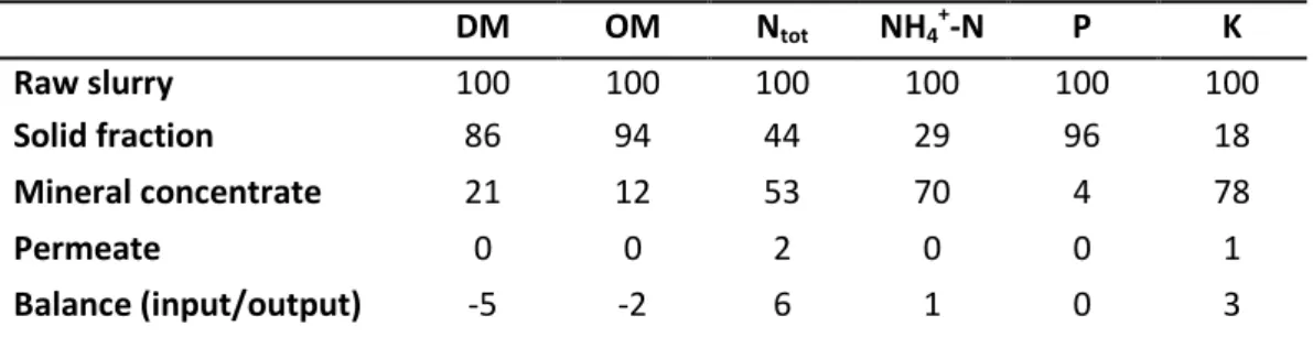
Table 2 shows the mass balance calculations of nutrients and organic matter of the manure
treatment installations. The input of raw slurry is set at 100. The installations also use additives such as acids, salts and flocculants during treatment, causing the production of dry matter and other parameters to exceed 100% in some installations. The N balance calculations show that on average 44% of the treated slurry N is recovered in solid fraction, 53% in the concentrate, and 2% in the permeate. The N balance suggests that, on average, one per cent of the slurry N was lost during the treatment process. The largest part of both NH4+-N and K (70 – 78%) is recovered in the concentrate.
Most of the organic matter (on average 94%) and P (on average 96%) is recovered in the solid fraction.
BIOREFINE – WP2 – A6 – P1, 2, 3, 8 – D 27
Table 2: Average relative mass distribution of dry matter (DM), organic matter (OM), total N, NH4
-N, total P and K over the end-products of slurry treatment in four plants in 2011. The balance is calculated as the difference between the input as raw slurry and the outputs as solid fraction, mineral concentrate, and permeate. The installations also used additives such as acids, salts and flocculants during treatment, causing the sum of the outputs of dry matter and other parameters to be higher than 100 % for the same installations.
DM OM Ntot NH4 + -N P K Raw slurry 100 100 100 100 100 100 Solid fraction 86 94 44 29 96 18 Mineral concentrate 21 12 53 70 4 78 Permeate 0 0 2 0 0 1 Balance (input/output) -5 -2 6 1 0 3
Source: Hoeksma P. and de Buisonjé F.E., (2012)
3.9.3 Process schemes
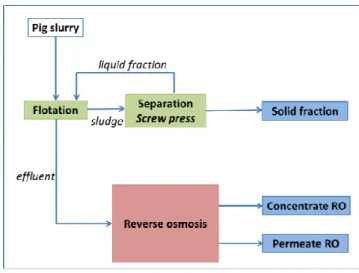
Figures 15 to 17 show some examples of process schemes based on reverse osmosis which can be
applied to pig slurry.
Figure 15: Separation of pig slurry using flotation and belt press, followed by reverse osmosis.
BIOREFINE – WP2 – A6 – P1, 2, 3, 8 – D 28
Figure 16: Separation of pig slurry using flotation and screw press, followed by reverse osmosis.
Source: Alterra – Wageningen
Figure 17: Sorting of co-digested pig slurry using centrifuge and ultrafiltration, followed by reverse osmosis.
Source: Alterra – Wageningen
3.9.4 End-products
The permeate obtained by reverse osmosis can be applied on land. Mineral concentrates can be applied in horticulture and agriculture. The concentrate after ultrafiltration is not considered an end-product and is therefore fed back into the manure processing installation.
The average composition of mineral concentrates originating from eight different Dutch manure/digestate processing installations using ultrafiltration or flotation in combination with reverse osmosis is shown in Table 3. For installation G, which was only operational for a few months in the start-up phase, there is no representative data available (Velthof, 2011) .
BIOREFINE – WP2 – A6 – P1, 2, 3, 8 – D 29
Table 3: Average composition (g/kg) of the mineral concentrates from different pilot plants in the Netherlands. Installation DM OM Ntot NH4 + -N P K A 29.1 10.5 6.41 5.92 0.20 7.08 B 39.1 18.2 7.17 6.86 0.01 6.75 C 40.2 19.3 8.92 7.77 0.34 8.44 D 25.8 7.81 5.26 4.72 0.11 6.81 E 19.4 6.32 4.16 3.56 0.08 5.53 F 33.9 13.7 8.12 7.13 0.26 8.08 H 113 70.7 11.0 10.5 0.27 15.7 Source: Velthof G., (2011)
The results confirm that mineral concentrates can be seen as nitrogen-potassium fertilisers. The average variations depend on the composition of the influent (manure slurry) and on the pre-treatment technique. The nutrient content is obviously higher in the products coming from installations using a centrifuge in combination with ultrafiltration (A and H) and installations using a sieve belt press in combination with flotation (B, C and F) than in those coming from installations using a screw press in combination with flotation (D and E) (Velthof, 2011).
3.9.5 Stage of development
The filtration technique applied to manure (or digestate) is being developed actively, but is not in general use yet (Lebuf et al., 2013).
3.9.6 Useful contact(s) for further information
Alterra Wageningen UR (The Netherlands)
Email addresses: [email protected], [email protected]
University of Ghent (Belgium)
Email addresses: [email protected], [email protected], [email protected]
VCM (Belgium)
BIOREFINE – WP2 – A6 – P1, 2, 3, 8 – D 30
3.10 Separation of pig manure under slats: the V-shaped scraper 3.10.1 Description of the technique
The system is based on the separation of faeces and urine within the building with a V-shaped scraper under slat. Urine is collected in the central gutter and continuously flows outwards. Solids are scraped off in the opposite direction several times per day. The high frequency of excreta removal leads to an improvement of production (Loussouarn et al., 2014) and a high effectiveness of the process: 90% of P and 55% of N concentrated in the solid phase (Landrain et al, 2009). The number of these buildings, inspired by Canadian and French experience in rabbit-breading, is growing uninterruptedly in the western part of France. The solid end-product can easily be carried to a fertiliser production platform or on-site composted. The system is shown in Figure 18.
Figure 18: V-schaped scraper in an experimental building in Guernevez.
Source: Agricultural Chambers of Brittany
3.10.2 Additional comments
Literature shows that urine and faeces separation and frequent removal from the building is beneficial for gas and odour emissions (up to 50% reduction of NH3 and N2O emission), improving
zoo-technical performance (improved ADG and lower FCR).
3.10.3 Useful contact(s) for further information
AILE (France)
Email address: [email protected]
1. V bottom
2. Canal for urine collection 3. Thin slit
BIOREFINE – WP2 – A6 – P1, 2, 3, 8 – D 31
4 Techniques for nutrient recovery from manure in development
4.1 Phosphorus precipitation4.1.1 Description of the technique
Struvite (magnesium ammonium phosphate hexahydrate or MAP) precipitation makes it possible to recover nitrogen (ammonium) and phosphorus (phosphate) from the thin fraction of manure (Figure
19). Since nitrogen is much more concentrated than phosphorus, both P (as phosphoric acid) and Mg
(as magnesium oxide) have to be added. The pH increase to 8.5-10, necessary for precipitation, is obtained by adding NaOH. Subsequently, the insoluble struvite precipitates under the form of crystals in a crystallisation reactor. The crystals can be separated from the liquid stream by means of sedimentation (Lemmens et al., 2007). In this way, about 90 % of the nitrogen and phosphorus are removed from the thin fraction (Melse et al., 2004). Besides the precipitation as struvite, phosphorus can also be removed as calcium-, iron- or magnesium phosphate (Lemmens et al., 2007; Melse et al., 2004).
Figure 19: Schematic overview of the struvite precipitation technique to recover nitrogen and phosphorus from manure.
Source: modified from Melse R.W. et al., (2004)
Investigations have recently shown that it is possible to recover phosphorus from both liquid and solid fractions from animal manure, even without adding an external phosphorus source. Figure 20 illustrates the process of phosphorus precipitation applicable to these types of waste. The unit operations are described more in detail underneath.
BIOREFINE – WP2 – A6 – P1, 2, 3, 8 – D 32 Size flexible separator Precipitation system Solid fraction
Liquid fraction with a low P content
N-stripper
Manure with a reduced P (and N) content Phosphate preciptates NH4 solution Crop required N-P adjusted manure products Liquid fraction Ca Phosphate Mg phosphate
Solid fraction with a low P content
Secundary resources
Figure 20: General scheme of manure treatment to recover phosphate precipitates in order to reduce the P content in manure.
Source: Alterra – Wageningen; Schoumans O. et al., (in preparation)
4.1.2 Unit operations
Separation
In the first step, slurry is divided into a liquid fraction and a solid one. The separation techniques highly determine the P distribution over the liquid and solid phase. By using a low tech separation technique (like screw press, belt press) a significant quantity of phosphates will end up in the liquid fraction together with the fine organic matter substances. By using state-of-the-art separation techniques (centrifuges / decanters), most of the phosphate will accumulate in the solid fraction and the treatment of the solid fraction becomes essential. Massé et al. (2005) showed that in slurry more than 70% of the undissolved P was present in particles with sizes between 0.45 and 250 µm.
Acidification
The pH of pig slurry usually fluctuates between 7 and 8. Phosphates are widely associated with precipitates of calcium such as di-calcium phosphate, or with ammonium and magnesium such as struvite (Bril & Salomons, 1990). About 70-90% of the P in manure is in the form of mineral P. The other part is mainly organic P. The amount of dissolved P is very low. It is difficult to extract P from manure directly. Several steps are needed to this end. Therefore, acidification of the pigsty slurry or slurry fractions by using sulphuric or formic acid in order to increase the amount of dissolved phosphorus in the manure and the P-concentration in the liquid phase might be necessary.
BIOREFINE – WP2 – A6 – P1, 2, 3, 8 – D 33
Struvite precipitation
Struvite formation in animal manure is admittedly being studied but mainly in laboratories (Greaves et al., 1999; Luo et al., 2001; Çelena et al., 2007; Szogi & Vanotti, 2009; Wahal et al., 2011; Shen et al., 2012; Wendler Fernandes et al., 2012). The pH determines the quantity of phosphorus precipitates (Colsen, 2002; Gadekar et al., 2009; Ehlert et al., 2013). The following reactions may occur after addition of a soluble Mg-source (e.g. MgCl2):
Mg2+ +NH4+ + HPO42- + 6H2O MgNH4PO4.6H2O + H+
Eq.2: Magnesium ammonium phosphate (MAP): NH4-struvite (8.5 < pH < 9.5) Mg2+ + K+ + HPO
42- + 6H2O MgKPO4.6H2O + H+
Eq. 3: Magnesium potassium phosphate: K-struvite (9 < pH < 10.5)
Mg2+ + HPO42- + 6H2O MgHPO4.6H2O
Eq. 4: Magnesium hydrogen phosphate (pH < 8.5)
The crystallization of struvite is initiated by nuclei such as sand grains present in pig slurry. An optimal ratio of Mg:NH4:PO4 of 1:1:1 is needed to form struvite, which means that magnesium has to
be added to ensure the formation of struvite .
In order to produce calcium-phosphate precipitates more process stages are needed. At first, a large part of the phosphate minerals available in manure or manure fractions need to be released by lowering the pH. Phosphorus that has been released (mainly as PO43-) at a lower pH, can be
recovered by adding an alkaline source, for example Ca(OH)2, forcing precipitation of calcium
phosphates which can finally be removed from the solution by filtering the suspension. The Ca~P precipitates are non-crystalline and often mixtures of monocalcium phosphates and dicalcium phosphates.
Product separation
A final separation step is needed in order to collect the precipitates. If the struvite crystals are big enough, simple coarse separation techniques can be used. To retrieve calcium phosphate, high tech separation techniques are needed to recover all precipitates. Besides, the retrieved manure slurry will have a reduced P content (optional N content) more compatible with crop requirements. Furthermore, much more treated manure can be applied on agricultural land allowing for the application standards for both nitrogen (e.g. 170 kg N/ha as mentioned in the Nitrates Directive) and phosphorus (in countries such as the Netherlands, where also P is regulated,). Optionally, the liquid fraction can be treated to remove NH3/NH4 by stripping in order to reduce the nitrogen content in
the slurry as well.
4.1.3 Process schemes
Several pilot plants for the recovery of phosphorus from pig slurry have been built in The Netherlands and France and are described below.
BIOREFINE – WP2 – A6 – P1, 2, 3, 8 – D 34
(1) Recovery of Mg-phosphates from the liquid fraction of manure
Figure 21 shows the operating units needed to recover P from the liquid fraction of manure (as
tested at a Dutch pilot plant for pig slurry).
Separator (700 µm) Mixing tank Buffer tank Separator (300-400 µm) Separator; rotating cloth (80-120 µm) manure tank Solid fractions Flow to be processed Liquid fractions MgCl 2 Wet Mg~P cake Liquid fractions with reduced P (& N) content NaOH
Figure 21: General scheme of P recovery from the liquid fraction of manure.
Source: Alterra – Wageningen; Schoumans O. et al., (in preparation)
From a tank with pig manure, a flow is separated into a solid fraction and a liquid fraction. A two-step separation technique is used. The first separator is used to remove the real coarse material in order to prevent damage to the second separator. The second separator is a 300-400 µm sieve belt press used to treat the solid fraction. By using the relative coarse sieve, a significant part of P penetrates the liquid fraction which is collected in a mixing tank. The pH of the liquid fraction is about 8 and can be adjusted to pH 9 by adding NaOH. Subsequently, MgCl2 is added to initiate the
precipitation of struvite or other Mg-phosphates. In the mixing tank, the suspension is rotated slowly to ensure a good contact between Mg and the liquid manure fraction without destroying the struvite. The suspension can be taken to a buffer tank to facilitate further precipitation. A rotating cloth separator is used (80-120 µm) to collect the struvite and/or other magnesium phosphates.
(2) Recovery of Ca-phosphates from the solid fraction of manure
Figure 22 shows the operating units required to recover P from the solid fraction of manure (as
BIOREFINE – WP2 – A6 – P1, 2, 3, 8 – D 35 Manure separator
Manure
tank
Liquid fraction H2SO4 Solid fraction Fil te r Ca(OH)2 P-sollution Fil te r Ca~P (solid) manure P↓ Industry regioFigure 22: General scheme of P recovery from the solid fraction of manure.
Source: Alterra – Wageningen; Schoumans O. et al., (in preparation)
From a tank with pig manure (or digested pig manure), a flow of pig manure is separated into a solid fraction and a liquid fraction. A high tech separation technique (decanter/centrifuge) is used to collect most of the mineral phosphates in the solid fraction. The pH of the solid fraction is about 8 and will be reduced to a maximal pH of 5. At this pH, almost all of the mineral phosphates become soluble. Higher values can also be chosen if only part of the phosphate has to be extracted. After solubilization of the phosphates at lower pH, the solution is filtered (screw press; 50-100 µm) and the solid fraction is temporarily set aside. Subsequently, calcium hydroxide is added to the solution until a pH of 8 is reached. At this pH, calcium phosphates are formed directly. This suspension is collected after filtering (screw press; 50-100 µm). The remaining solution (with high pH but low P concentration) is combined with the acidified solid fraction to produce pig slurry with a lowered P content. With this approach, almost 80-100% of the solubilized P can be recovered (Schoumans et
al., 2014). The final results of these Dutch pilots will be available and published in 2016.
(3) Recovery of phosphate salts from biologically treated pig slurry
Within the framework of phosph’OR project, IRSTEA (FR) has developed a pilot process to recover P bound to organic matter by acidification and phase separation, as shown in Figure 23. This pilot is being tested on a pig farm in Brittany. Apart from this plant, there is no full-scale P-recovery site processing animal waste in France.
BIOREFINE – WP2 – A6 – P1, 2, 3, 8 – D 36
Figure 23: Plant of struvite precipitation from pig slurry used in Brittany (France).
Source: AILE
The different treatment steps of the French pilot plant are:
Raw pig slurry treatment
The pilot has been developed with the view of recovering P from treated slurry. The first step is a biological treatment by nitrification/denitrification. During the aerobic stage of the nitrification/denitrification process, the amount of dissolved P increases. The treated pig slurry has a low buffer effect because of nitrogen removal and a low amount of NH4+. Raw pig slurry or even
digestate could be used, but the amount of reactant for the next step will be higher.
Acidification
The second step is the acidification of pigsty wastewater to increase the amount of dissolved phosphorus in the manure and its concentration in the liquid phase. Formic acid is used to obtain a pH value of about 4.5.
Solid/liquid separation
The solid and liquid phases are separated by means of a drain table and polymers.
Adding MgO and precipitation
Magnesium oxide is added to the liquid effluent in the reactor and regulated with the pH value. Agitation is a major factor to dissolve MgO in solution, allowing Mg2+ to form struvite crystals, within the reaction:
Mg2+ + PO
43- + NH4+ ↔ MgNH4PO4 (struvite)
BIOREFINE – WP2 – A6 – P1, 2, 3, 8 – D 37
Filtration
The effluent is then filtered through a 100 µm screen. The solid fraction obtained is a mix of struvite, magnesium and calcium phosphate. The process makes it possible to recover from 96 to 100% of the phosphorus from the treated slurry.
4.1.4 End-product and use
The struvite (MgNH4PO4.6H2O) crystals can generally be applied on crop land as a slow-release
P-fertiliser. Furthermore, a fraction with a very low phosphorus and nitrogen content can be applied on cropland as well. In the latter case, the concentration of other salts (such as K) will be the limiting factor. In some regions (e.g. Wallonia, Belgium), legal measures do not allow using such fertilisers.
4.1.5 Stage of development
The application of struvite precipitation from animal manure is still very limited. There are several pilot plants and one full-scale system in The Netherlands (Lebuf et al., 2013). One of the biggest difficulties is that the physico-chemical removal of N and P from animal slurry is hard to control due to the variable composition of the manure (Lemmens et al., 2007) and the high organic matter content (Cerrillo et al., 2014). Two examples of such plants are provided above.
4.1.6 Useful contact(s) for further information
AILE (France)
Email address: [email protected]
Alterra Wageningen UR (The Netherlands)
Email addresses: [email protected], [email protected]
University of Ghent (Belgium)
Email addresses: [email protected], [email protected], [email protected]
VCM (Belgium)
BIOREFINE – WP2 – A6 – P1, 2, 3, 8 – D 38
4.2 Pyrolysis - Biochar production from solid manure 4.2.1 Description of the technique
Pyrolysis is a thermochemical conversion of biomass resulting from heating under low oxygen conditions. Almost any kind of solid biomass can be used, such as solid manure or chicken poultry. The decomposition process consists of three phases: gas, liquid (bio-oil) and a solid fraction called “biochar”. The distribution and the quality of the end-product depend on the reaction conditions and the feedstock characteristics. Figure 24 shows the distribution of products according to the treatment applied to biomass.
Amongst the technologies above, some are suited to biorefinery. More specifically, bio-oil production could be the core of biorefinery from solid biomass (Ronsse F., 2013). However all these technologies are at different stages of development (AILE, 2015). Applications for manure processing are especially at pilot stage or in development.
Traditional charcoal production is largely developed, but traditional slow pyrolysis techniques are polluting and energetically non-efficient (Hazard et al., 2005). The interest in modern pyrolysers is due to the potential agronomic interest in biochar, which will be discussed below.
Product distribution (wt%)
Torrefaction Slow pyrolysis
Flash
pyrolysis Gasification Combustion
Gas 5 35 13 85 (Syngas) 99 (CO2) Liquid 20 30 75 (bio-oil) 5 - Solid 75 35 (biochar) 12 10 1 (Ashes) 200-300°C 1h Atm. P No O2 220°C few hours 22 bar No O2 350-550°C few sec 700- 1500°C few minutes Atm. P 1/3 O2 >800°C few hours Atm. P O2 in excess
Figure 24: Thermochemical conversion of biomass and products distribution based on reaction conditions.
Source: modified from Ronsse F. et al., (2013)
4.2.2 End-products
The biochar quality depends on the composition of the feedstock (nutrients, lignin, cellulose, hemicellulose), the pyrolysis process (temperature, time, pressure, etc.) and the end-product. Table
4 shows the composition of biochar, depending on the input material.
Heat
BIOREFINE – WP2 – A6 – P1, 2, 3, 8 – D 39
Table 4: Characteristics of biochar from agricultural waste.
Biomass Source T° process N (%) P (%) pH
(water)
CEC
(cmol/kg) C/N
Pig manure (A) [1] 400 2.2 2.4 - -
Pig manure (B) [1] 700 1.2 3.5 - -
Poultry Litter [2] 400 3.5 3 10.1 61.1 11
Woodchips [2] 350 0.57 0.06 7 4.7 144
Sources: Faessel L., (2013)
4.2.3 Benefits and applications of biochar
There are many different applications for biochar, which can be sorted by increasing added value: fuel, soil amendment, active charcoal for air treatment.
When used as a soil amendment, biochar has a lot of advantages: - Carbon sequestration and greenhouse gas effect limitation;
- Ability of soil to retain nutrient thanks to high surface charge density; - Increasing pH;
- Effects on physical properties of soil (water retention, cation exchange capacity), depending on soil type;
- Effects on biological properties of soils (increased microbial biomass).
Although lots of studies are available, the mechanisms are not clear, additional studies are needed to assess the benefits under different soil conditions.
4.2.4 Useful contact(s) for further information
AILE (France)
BIOREFINE – WP2 – A6 – P1, 2, 3, 8 – D 40
5 List of useful contacts
BELGIUM
Flemish Coordination Centre for Manure Processing (VCM)
Abdijbekestraat 9, 8200 Bruges
Contact: [email protected]
Gembloux Agro-Bio Tech – University of Liège
Passage des Déportés 2, 5030 Gembloux
Contacts: Frank Delvigne, [email protected] ; Cédric Tarayre, [email protected]
University of Ghent – Faculty of Bioscience Engineering
Coupure Links 653, 9000 Gent
Contacts: Erik Meers, [email protected] ; Evi Michels, [email protected]
Vlaamse Compostorganisatie (VLACO)
Stationsstraat 110, 2800 Mechelen Contact: [email protected]
FRANCE
Association d’initiatives Locales pour l’Energie et l’Environnement (AILE)
Rue de Saint-Brieuc CS 56520, 35065 Rennes
Contacts: Adeline Haumont, [email protected]
Chambres d’agriculture de Bretagne, Pôle Porc-aviculture
Rond-Point Maurice Le Lannou, ZAC Atalante Champeaux - CS 74223, Rennes Cedex Contact: Aurore Loussouarn, [email protected]