HAL Id: hal-01611010
https://hal.archives-ouvertes.fr/hal-01611010
Submitted on 15 Feb 2019
HAL is a multi-disciplinary open access
archive for the deposit and dissemination of
sci-entific research documents, whether they are
pub-lished or not. The documents may come from
teaching and research institutions in France or
abroad, or from public or private research centers.
L’archive ouverte pluridisciplinaire HAL, est
destinée au dépôt et à la diffusion de documents
scientifiques de niveau recherche, publiés ou non,
émanant des établissements d’enseignement et de
recherche français ou étrangers, des laboratoires
publics ou privés.
Laser transmission welding of composites - Part B:
Experimental validation of numerical model
Andre Chateau Akue Asseko, Benoît Cosson, Fabrice Schmidt, Yannick Le
Maoult, Rémi Gilblas, Eric Lafranche
To cite this version:
Andre Chateau Akue Asseko, Benoît Cosson, Fabrice Schmidt, Yannick Le Maoult, Rémi Gilblas, et
al.. Laser transmission welding of composites - Part B: Experimental validation of numerical model.
Infrared Physics and Technology, Elsevier, 2015, 73, p. 304-311. �10.1016/j.infrared.2015.10.005�.
�hal-01611010�
Laser transmission welding of composites – Part B: Experimental
validation of numerical model
André Chateau Akué Asséko
a,b,c,⇑, Benoît Cosson
a,c, Fabrice Schmidt
b, Yannick Le Maoult
b, Rémi Gilblas
b,
Eric Lafranche
a,caMines Douai, Department of Polymers and Composites Technology & Mechanical Engineering, 941 rue Charles Bourseul, CS 10838, F-59508 Douai Cedex, France bUniversité de Toulouse, Mines Albi, ICA (Institut Clément Ader), Campus Jarlard, F-81013 Albi Cedex 09, France
cUniversité de Lille Nord de France, 59000 Lille, France
Keywords: Infrared welding Laser beam spread The widening Thermal simulations Continuous fiber composite Experimental setup
a b s t r a c t
In this paper, experimental measurements are performed to confirm the global analytical model (refraction and absorption phenomena) presented in the previous work. Initially, an experimental approach to the estimation of the laser beam spread in a semi-transparent composite and at interface (width of the output beam) subjected to an incident heat flux, was presented. This parameter represents a fundamental input data for the global analytical model (refraction and absorption) during the numerical simulation of transmission infrared welding. Then, an experimental setup for the temperature measurement is performed using infrared camera, during infrared transmission welding of materials joints to validate the welding simulation results (a transient numerical model, based both on conduction and radiation mode heat transfer) with the developed analytical model. The commercial FEM software COMSOL Multiphysics!is used to compute temperature distribution by implementing a
radiative source term. Numerical simulations are compared with experimental data. The agreement between simulations and experiments is fair, which gives confidence to use the developed model with acceptable accuracy.
1. Introduction
In previous studies[1–3], a global analytical model (refraction and absorption phenomena) for the modeling of transmission laser/infrared welding process in thermoplastic composites has been developed. This model allows the description of the attenua-tion of the laser beam, the predicattenua-tion of the heat source in the laser welding process thermal simulations, in the case of UD (unidirec-tional) thermoplastic composites materials. Finally the model per-mits the computation of the three dimensional temperature field, during the welding process. This approach proves to be an efficient mean for the composites’ weldability determination and process optimization. The literature contains many researches on the modeling of laser/infrared transmission welding process for the
calculation of the temperature field assuming the radiative energy interface (radiative heat source) received at the interface. The absorption phenomenon for absorbent materials is modeled using
Beer–Lambert law assuming cold and non-scattering media [4].
The authors[5]assumed a heat flux density with Gaussian
distri-bution in the semi-transparent materials to estimate the radiative energy at the welding interface. In their contribution, Shanmugam
et al.[6]also considered the same assumptions. The authors[7]use
a simplified model for the diffused intensity into the material using the Beer–Lambert law with the laser beam. Most of the researchers
[8–10] consider that the laser beam is absorbed at the interface and in the volume of second material is transmitted according to
the Beer–Lambert. The following authors [11,12] have proposed
analytical general solutions (transient and steady state) to estimate the evolution of the temperature field at any point of the weld interface. They performed computation for fixed and mobile sources of heat, considering several forms of surface source: elliptical, circular, rectangular or square. In this current paper, experimental measurements are performed in order to confirm the global analytical model.
⇑Corresponding author at: Université de Toulouse, Mines Albi, ICA (Institut Clément Ader), Campus Jarlard, F-81013 Albi Cedex 09, France.
E-mail addresses: andre.akue.asseko@mines-douai.fr (A.C. Akué Asséko),
cosson@mines-douai.fr (B. Cosson), fabrice.schmidt@mines-albi.fr (F. Schmidt),
yannick.lemaoult@mines-albi.fr(Y. Le Maoult),rgilblas@mines-albi.fr(R. Gilblas),
2. Experimental estimation approach of the light scattering laser beam in a thermoplastic composite
2.1. Principle of the test method
The aim of measurements is the characterization of the interac-tion between the laser beam and the semi-transparent thermo-plastic composite (path of the laser beam into the composite). The tests are based on the visualization of the spread or the width of the laser beam (by measurement of the widening of the beam task) on the back surface of a semi-transparent composite sample subjected to a surface laser flux. This parameter is a function of the thickness, refraction index of matrix and fiber volume fraction and microstructural arrangement in the composite. The idea is to be able to characterize the optical spot of the laser beam at the inter-face of the laser welding process. The refraction phenomenon of the laser beam caused to each fiber matrix interface in the semi-transparent composite will be observed. Two types of tests were carried out for this purpose: one test without composite (on the sheet of paper) for the measurement of the initial spot of the laser beam. This test requires the use of a white paper sheet (weight of
80 g/m2) which serves as the output screen and one test with the
polycarbonate glass fiber composite. The material considered in this study is Macrolon 2405 Polycarbonate with Glass fiber (40%). The laser with 1 mW of power (in static mode) is pointed on the
sheet of paper for a few seconds (Fig. 1a). During this time an
ALLIED high resolution visible camera (5 MP) placed on the back face, records the images of the beam spot. The obtained result will be compared with PC-glass composite test. The incident laser beam has a rectangular shaped profile with a uniform distribution of light intensity.
In the case of the measurement with the semi-transparent com-posite (Fig. 1b), the laser is pointed on the semi-transparent com-posite surface and a sheet of paper is placed behind the latter, in order to simulate the interface area.
2.2. Result and analyses
The digital images obtained by the grayscale mode (Fig. 2) are
then imported into the numerical calculation software as Matlab (Fig. 3) in order to plot the profiles of light intensities of pixels. A program was developed for this purpose. Using these profiles we can estimate the spread of the laser beam.
Fig. 2a and b respectively shows the reference optical spreads on the paper and on the back surface of the polycarbonate glass fiber composite (laser beam perpendicular to the fiber direction).
There is no spread on the paper (Fig. 2a), whereas inFig. 2b, we
observed a beam spread on back surface of the composite. This phenomenon is due to the presence of fibers in the material which cause their deviation (refraction phenomenon). There is a widening of the laser beam diameter when it passes through the semi-transparent PC-glass composite.
Nomenclature
MP megapixel
E thickness of material (mm)
fe experimental widening ratio
fN numerical widening ratio
Lcomposite experimental spread in composite (pixel)
Lpaper experimental spread in sheet of paper (pixel)
r
compositenumerical spread at the interface of composite (mm)r
initial spatial shape parameter of the initial laser beam (mm)nf refractive index of fiber
nm refractive index of matrix
hc convection heat transfer coefficient (W/m2K)
hr radiative heat transfer coefficient (W/m2K)
Ts surface temperature (K)
T0 ambient temperature
Fig. 4shows the reference light intensity profiles (on paper) and the back face after crossing the PC glass composite (thickness 1.64 mm). We note well, a decrease or attenuation of the maximum of light intensity and a widening of the beam (the
phenomena mentioned in[2]) in the composite PC glass.
The estimated average reference spread of laser beam on paper is 134 pixels and 418 pixels on the back surface of semi-transparent composite for three measurement tests.
In the literatures[13–15], the Gaussian beam spread width or
Gaussian beam radius is the radius at which the intensity is
1/e2= 0.135 times the maximum value (where the laser beam
intensity decrease with 1/e2). By computing the beam widening
ratio fe¼ Lcomposite
Lpaper ¼ 3:11, we obtain a widening factor of approxi-mately 3 of the incident laser beam radius at the interface of the semi-transparent composite of 1.64 mm.
This parameter experimentally determined was compared to the numerical simulation result by ray tracing. A parametric iden-tification between ray tracing and a light scattering analytical
model developed in [2]was carried for this purpose. The result
of this parametric study is presented inTable 1.
The calculated numerical laser beam spread at the interface of composite (E = 1.64 mm) is 5.875 mm. By performing the calcula-tion of the widening ratio of the beam as previously, we obtain fN¼rcomposite E¼1:64 mmrinitial laser beamð Þ¼ 2:9375.
We note a fair agreement of widening ratio between experi-mental measurement and parametric identification method. The relative error between the two approaches is less than 6%. The experimental method setting up for the measurement of the laser beam spread or the widening in semi-transparent glass fiber com-posite is validated. This method enables to estimate the widening factor (due to internal refraction phenomenon) of the initial laser beam diameter in the semi-transparent composite and hence to estimate the spread of the beam at the interface for a given thick-ness. This parameter will be an important input data for the global analytical model during numerical welding simulation.
3. Heating stage simulations validation of composites transmission infrared welding
3.1. Experimental measurements
Experimental measurements are performed in order to measure temperature during infrared transmission welding of Polycarbonate (Macrolon 2405) with Glass fiber composite (semi-transparent component) and Polycarbonate added 0.0243% carbon black (CB) (absorbent component). Infrared welding of composites involves two joining parts: one semi-transparent to Fig. 2. Images recorded by the high resolution camera.
Fig. 3. Imported images in Matlab.
Fig. 4. Spread of the laser beam profiles. Table 1
Numerical simulation with glass fiber composite (40%): (nf= 1.53; nm= 1.586).
rinitial laser beam(mm) 2
the IR wavelengths and the other part is absorbent in the same wavelengths. The two parts are positioned together before the welding. Surface treatments are not need as in the gluing process. The infrared beam energy is transmitted through the semi-transparent material and is absorbed within the surface of the
sec-ond material (Fig. 5). The bonding between the two parts allows
the heating of the semi-transparent part by thermal conduction. Thus, melting and fusion of the both materials interface occurs
(the bonding between the two parts occurs when T > Tmeltin this
area). The energy is deposited at the interface in a localized volume causing the formation of a weld zone.
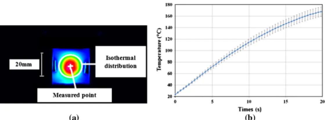
The experimental device, mentioned below (Fig. 6), is used for
the temperature measurement. A halogen lamp MAZDA GY.6.35 (nominal power: 50 W, 12 V) is focused by a precision Edmund Optics ellipsoidal reflector with 115 mm for the diameter and two focal points (17 mm and 272 mm). When a light source is placed at the first focal point, the source will refocus at the second focal point. The protected aluminum coating features broadband high reflection through the visible and IR spectra (90%); it comes to heat the interface of the two materials. The temperature field on the back surface of the absorbent material is measured using
again the CS 325 FLIR infrared camera [7.5–13.5
l
m].Fig. 7a and b shows respectively the measured thermal image on the back of the absorbent parts and the evolution (center) of the average temperature field measured for about 20 s of heating process, for three tests. The error bars represent the measured minimum and maximum values during the tests.
3.2. Microstructural observations of welding zones
InFig. 8(bottom), we carried out a debonding of the welded joint in order to observe its failure mode. The welding quality of the two parts depends on it. It should be noted that there are two failure modes. An adhesive failure which takes place at the welding interface and separating the two welded surfaces cleanly and without carry forward of matter from one surface to the other
[17]. However, on a cohesive failure, the two welded parts are
mixed up. This failure mode characterizes a good welding quality
[18]. InFig. 8(bottom), we find the mixed PC glass fiber and PC with CB surfaces in some areas. Macromolecular structures on each side of the welding interface have been mixing in order to establish an entangled network. We observed a cohesive failure of our welded materials. This visual comparison provides the first infor-mation on the welding performed quality. Macromolecular struc-tures can be studied using the diffusion theory (macroscopic approaches to evaluate the depth of molecular diffusion related to inter-diffusion phenomenon in the welded samples, in order to confirm the origin of the observed failure modes evolution). It will be a more detailed study in another paper.
3.3. Validation of the infrared heating simulations
In this section, numerical simulations are compared with experimental data in order to confirm the global analytical model (refraction and absorption phenomena). The commercial FEM
Fig. 5. Schematic of samples.
software COMSOL Multiphysics!is used to obtain the numerical
temperature field by implementing a volume heat source. The distribution of the temperature over time in the back surface of absorbent material is computed by solving numerically the heat equation. Then, experimental results and numerical results are compared.
The following assumptions are made for simplifying the numerical model development:
1. Focused lamp enables the simulation of a localized heating point considered as a gaussian shape.
2. A perfect interface is assumed between the two parts as in[10]
due to a reduce thickness of the sample and the good quality of the surface contact.
3. Gaussian distribution of laser intensity is considered at the welding interface (analytical model).
4. Infrared volume absorption in the second part (absorbent). Fig. 7. Measured thermal image (a) temperature variation on the back surface of absorbent part (b).
5. Both forward and back surfaces are subjected to cooling by the
convective heat transfer with ambient air (hc) and radiative
losses (hr).
In order to determine the temperature field during the laser/ infrared welding process, thermophysical and optical properties of the materials to be welded are required as input parameters to
model the thermal process properly (previous study in[16]).
At initial time (t = 0 s), the two parts are at measured uniform
ambient temperature T0= 293.15 K Physical properties of air are
evaluated at the defined average temperature as in[19]. In this
study, the maximal temperature reached on the back surface of the absorbent material Tsis 441.33 K. The value of hris calculated
at different temperature and stored in a look-up table as tempera-ture dependant material property data.
A quadratic meshed model is structured (Fig. 9). Fine meshes
(2250 elements) are created in the region near the laser path due to the high heat flux involved in that area.
Numerical simulation is compared to experimental data (Fig. 10) versus time.Fig. 10highlights several issues:
1. First of all, we find a very good agreement between the numer-ically predicted temperature by the analytical model and the experimentally measured temperature by infrared camera. At the end of the heating step at the interface, the error on the temperature is less than 2%.
2. The comparison shows that simulation result has a good corre-lation with experimental result. Heat exchanges have been cor-rectly estimated. This gives actually, a good agreement with the developed analytical model.
In addition,Fig. 11compares measured and simulated
temper-ature profiles on the back surface of the absorbent part at the end of welding (t = 18 s), following the spatial x (horizontal profiles) and y (vertical profiles) distributions. The spatial profiles in x-direction are more spread (transversal x-direction to the fibers in the case of the UD composite) than those in the y-direction.
We have noticed a fair agreement between the measurement and numerical simulation. Error for the temperature is less than 5%. This comparison of the measured and simulated profiles also allows the validation of the model.
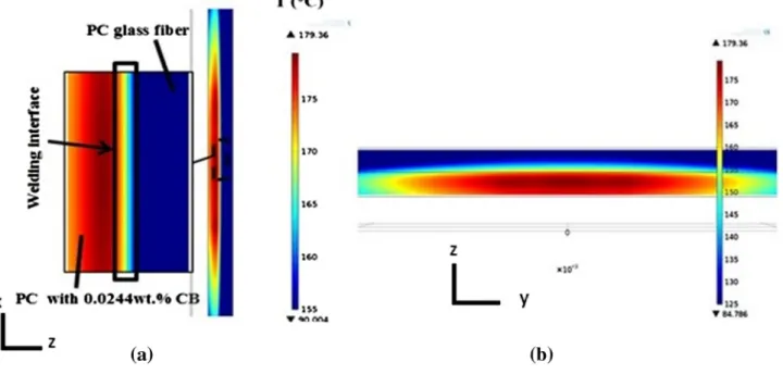
Fig. 12(a and b) shows the temperature field within the materi-als. The heat generated at irradiation zone is gradually transferred to surrounding material by effect of thermal conduction. It can be noticed that the maximum of the temperature field occurring in the absorbent material is 179.36"C but not at the joint interface (Fig. 13). This temperature is greater than the glass transition
tem-perature of polycarbonates, Tg (135–140"C). We observe the
impact on the exposure time for a good welding. The region above
Tgshows the weld depths in both parts from interface. This
phe-nomenon indicates volumetric absorption as in[14]of the infrared
energy within the absorbent part which we modeled. This induces asymmetric weld pool geometries. Simulation confirms that the heat is accumulated in the absorbent part. An ‘‘overheating” occurs: the temperature in this part is greater than at the interface. 4. Conclusion and prospects
The aim of this study was to validate or to confirm experimen-tally the global analytical model (refraction and absorption
phe-nomena) presented in the previous work [3]. First, an
experimental method setting up for the measurement of the laser beam spread or the widening (an important input data for the glo-bal analytical model during numerical welding simulation) in semi-transparent glass fiber composite is presented. This method enables to estimate the widening factor (due to internal refraction phenomenon) of the initial laser beam diameter in the semi-transparent composite and hence to estimate the spread of the beam at the interface for a given thickness. We developed there-after, a transient numerical model, based both on conduction and radiation mode heat transfer whose goal is to simulate infrared transmission welding process. The commercial FEM software Fig. 9. Mesh of the two welded parts.
Fig. 10. Experimental and numerical temperatures on the back face of the absorbent composite versus time (center of the sample).
COMSOL Multiphysics!was used to obtain the temperature field
by implementing a developed 3D heat source. The numerical results are compared with experimental results, experimental setup for the temperature measurement performed using infrared camera, during infrared transmission welding of materials joints. The comparison shows a fair agreement between them, which gives confidence to use the developed model with acceptable accuracy.
In future works, a coupling between the welding process parameters and the mechanical properties of the weld seam may be achieved. Mechanical characterization would then enable to verify the mechanical strength of welded joints. A study on the determination of the depth of macromolecular diffusion related to the inter-diffusion phenomenon within the welded samples should be conducted. This study will highlight and better describe the origin of the observed failure mode or fracture surfaces.
Conflict of interest
The authors declare that there is no conflict of interest. Acknowledgement
This work could not be possible without the assistance of Jean Michel MOUYS (ICA-Albi) or helping with the implementation of the experimental set-up.
References
[1] A.C. Akué asséko, B. Cosson, F. Schmidt, Y. Le Maoult, E. Lafranche, Modelling and simulation of transmission laser welding process of thermoplastics composites, Esaform (2013).www.scientific.net/KEM.
[2] A.C. Akué asséko, B. Cosson, F. Schmidt, Y. Le Maoult, E. Lafranche, Analytical and numerical modeling of light scattering in composite transmission laser Fig. 12. Temperature field within the materials (t = 20 s).
welding process, Int. J. Mater. Form. (2013), http://dx.doi.org/10.1007/s12289-013-1154-7.
[3] A.C. Akué asséko, B. Cosson, F. Schmidt, Y. Le Maoult, R. Gilblas, E. Lafranche, Thermal modeling in composite transmission laser welding process: light scattering and absorption coupling, Esaform (2014),http://dx.doi.org/10.4028/ www.scientific.net/KEM.611-612.1560.
[4]R. Siegel, J. Howell, Thermal Radiation Heat Transfer, third ed., Hemisphere Publishing Corporation, 1992.
[5]G.N. Labeas, G.A. Moraitis, C.V. Katsiropoulos, Optimization of laser transmission welding process for thermoplastic composite parts using thermo-mechanical simulation, J. Compos. Mater. 44 (1) (2010) 113–130. [6]N.S. Shanmugam, G. Buvanashekaran, K. Sankaranarayanasamy, S. Ramesh
Kumar, A transient finite element simulation of the temperature and bead profiles of T-joint laser welds, Mater. Des. 31 (9) (Oct. 2010) 4528–4542.
[7]D.A. Grewell, A. Benatar, Plastics and Composites: Welding Handbook, Hanser Verlag, 2003.
[8]J.M.P. Coelho, M.A. Abreu, F. Carvalho Rodrigues, Modelling the spot shape influence on high-speed transmission lap welding of thermoplastics films, Opt. Lasers Eng. 46 (1) (2008) 55–61.
[9]M. Ilie, J.-C. Kneip, S. Matteï, A. Nichici, C. Roze, T. Girasole, Through-transmission laser welding of polymers – temperature field modeling and infrared investigation, Infrared Phys. Technol. 51 (1) (2007) 73–79. [10] M. Ilie, D. Grevey, S. Mattei, E. Cicala, V. Stoica, Diode laser welding
of ABS: experiments and process modeling, arXiv:1002.1241, February 2010.
[11]Z.B. Hou, R. Komanduri, General solutions for stationary/moving plane heat source problems in manufacturing and tribology, Int. J. Heat Mass Transfer 43 (10) (2000) 1679–1698.
[12] K.J. Suthar, J. Patten, L. Dong, H. Abdel-Aal, Estimation of Temperature Distribution in Silicon During Micro Laser Assisted Machining, pp. 301–309, January 2008.
[13]M. Ilie, D. Grevey, S. Mattei, E. Cicala, V. Stoica, Diode laser welding of ABS: experiments and process modeling, Opt. Laser Technol. 41 (5) (2009) 608–614. Polyweldsys.
[14]B. Acherjee, A.S. Kuar, S. Mitra, D. Misra, Effect of Carbone black on temperature field and weld profile during laser transmission welding of polymers: a FEM study, J. Mater. Process. Technol. 44 (2012) 514–521. [15]I.G.-C. Rodrigues-Vidal, E. Quintana, Laser transmission welding of ABS: effect
of CNTs concentration and process parameters on material integrity and weld formation, Opt. Laser Technol. 57 (2014) 194–201.
[16]AC. Akué asséko, B. Cosson, F. Schmidt, Y. Le Maoult, E. Lafranche, Laser transmission welding of composites – Part A: thermo-physical and optical characterization of materials, Infrared Phys. Technol. 72 (2015) 293–299. [17] E. Debondue, Les mécanismes de formation et de cohésion des lignes de
soudure de flux dans les pièces injectées en matière plastique, PhD Thesis, Ecole de Lille 1 Science et Technologie, 1997 (in French).
[18] M.O. Mairagouna, Approche probabiliste du comportement mécanique des thermoplastiques assemblés par soudage laser, PhD Thesis, Ecole des Mines de Paris, 2012 (in French).