HAL Id: hal-01004414
https://hal.archives-ouvertes.fr/hal-01004414
Submitted on 25 May 2021
HAL is a multi-disciplinary open access
archive for the deposit and dissemination of
sci-entific research documents, whether they are
pub-lished or not. The documents may come from
teaching and research institutions in France or
abroad, or from public or private research centers.
L’archive ouverte pluridisciplinaire HAL, est
destinée au dépôt et à la diffusion de documents
scientifiques de niveau recherche, publiés ou non,
émanant des établissements d’enseignement et de
recherche français ou étrangers, des laboratoires
publics ou privés.
Enabling model checking for collaborative process
analysis: from BPMN to ’Network of Timed Automata’
Sihem Mallek, Nicolas Daclin, Vincent Chapurlat, Bruno Vallespir
To cite this version:
Sihem Mallek, Nicolas Daclin, Vincent Chapurlat, Bruno Vallespir. Enabling model checking for
collaborative process analysis: from BPMN to ’Network of Timed Automata’. Enterprise Information
Systems, Taylor & Francis, 2014, pp.1-21. �10.1080/17517575.2013.879211�. �hal-01004414�
Interoperability is a prerequisite for partners involved in performing collaboration. As a consequence, the lack of interoperability is now considered a major obstacle. The research work presented in this paper aims to develop an approach that allows specifying and verifying a set of interoperability requirements to be satisfied by each partner in the collaborative process prior to process implementation. To enable the verification of these interoperability requirements, it is necessary first and foremost to generate a model of the targeted collaborative process; for this research effort, the standardised language BPMN 2.0 is used. Afterwards, a verification technique must be introduced, and model checking is the preferred option herein. This paper focuses on application of the model checker UPPAAL in order to verify interoperability require-ments for the given collaborative process model. At first, this step entails translating the collaborative process model from BPMN into a UPPAAL modelling language called ‘Network of Timed Automata’. Second, it becomes necessary to formalise interoperability requirements into properties with the dedicated UPPAAL language, i.e. the temporal logic TCTL.
Keywords: collaborative process; interoperability requirements; verification; model checker; model transformation; Network of Timed Automata
1. Introduction
In the current globalised environment, organisations are increasingly motivated to formalise their collaboration with partners through the use of collaborative process models. A collaborative process can be defined as a process whose activities belong to different organizations (Aubert and Dussart 2002). To improve the efficiency of a collaborative process, interoperability has become a prerequisite. Interoperability is defined as the ability of enterprises and entities within those enterprises to communicate and interact effectively (INTEROP2007; ISO/DIS2009). It is therefore critical for each partner in a collaborative process to first detect and then avoid or minimise potential problems induced by a lack of interoperability before any collaboration. To guide and assist these partners in resolving their interoperability problems, the present research work aims to facilitate problem detection in an anticipatory manner, i.e. prior to implementation of the collaborative process. Consequently, this research programme has been based on the following steps:
*Corresponding author. Email:[email protected]
Enabling
model checking for collaborative process analysis: from
BPMN
to ‘Network of Timed Automata’
Sihem Malleka, Nicolas Daclina
*, Vincent Chapurlata and Bruno Vallespirb
aEcole des Mines d'Alès, Laboratoire de Génie Informatique et d'Ingénierie de Production (LGI2P),
Parc Scientifique G. Besse, Site de l'EMA, Nîmes Cedex 1, 30035 France; bIMS-University Bordeaux 1, 351 cours de la Libération, 33405 Talence, France
(1) The collaborative process is modelled using a standardised and comprehensive notation, such as Business Process Modelling Notation (BPMN) (BPMN 2011), which serves to describe interoperability in order to enable its analysis.
(2) A general repository of interoperability requirements, i.e. a set of requirements that can be applied in any cases of process, is defined and used to guide problem detection in the collaborative process model.
(3) A formal verification technique can be feasible for checking if the collabora-tive process model meets interoperability requirements. This verification tech-nique is based on the model checker UPPAAL (Behrmann, David, and Larsen
2004).
(4) Lastly, a checklist of potential solutions is introduced, with these solutions themselves being arguable by means of verification, in order to solve the problem or at least minimise its effects.
The purpose of this paper focuses on Step 3 (for more details regarding the Step 1 and 2, the reader may refer to Mallek, Daclin, and Chapurlat2012; Mallek et al.2013). Precisely, this paper presents the conceptual and technical means for analysing the behavioural aspects of a collaborative process with regard to interoperability. Accordingly, a formal verification technique based on the principle of model checking can then be adopted to offer a dynamic vision of the system. This technique however remains difficult to both implement (due to its requirement of a strong formalisation) and apply in certain fields such as enterprise modelling (due to model formalisation difficulties). In light of these considerations, the present paper will argue and illustrate an approach to enhancing and implementing a verification technique based on model checking by use of the UPPAAL modelling language.
The actual implementation of such a verification technique requires, first of all, developing a model of the collaborative process that includes the language used by the chosen model checker, i.e. Network of Timed Automata (NTA). An NTA represents the behaviour of the analysed system, in this case the behaviour of the analysed collabora-tive process model. As a consequence, it is necessary to establish a relationship between the collaborative process model and its behavioural model targeted for analysis. This step requires proposing an operational semantic, i.e. a state transition system able to incorporate the expected behaviour of the collaborative process. In the present case, it becomes necessary to define a set of transformation rules for translating the collabora-tive process model into an NTA that can be analysed using UPPAAL. Each BPMN element thus features an operational semantic and is transformed into timed automata that respect this semantic. Second, the implementation of this verification technique entails formalising the interoperability requirements that take into account the formal language used by the UPPAAL model checker. Hence, it is important to formalise the relevant requirements, i.e. those intended to characterise the expected process behaviour with formal language.
This paper will focus on the proposed approach so as to enable verification of a collaborative process model; it has been organised as follows. Section 2 presents the context and problem statement specific to this mission. Section 3 offers a description of the modelling language and the chosen model checker UPPAAL principles. Section 4 then describes BPMN elements behaviour with UPPAAL. Section 5 explains and defines the steps by which the collaborative process model is translated into a NTA. Section 6 provides a case study illustrating the transformation rules and, finally, Section 7 sets forth a conclusion and plan for future works.
2. Context and problem statement
Verification is the confirmation by examination and proof of objective evidence that specified requirements have been met (ISO 1994). The goal inherent in this work is to prove model consistency by verifying that the requirements (relative to the model and interoperability) are met when constructing the model.
In our research work, the verification objective is to demonstrate that a set of selected interoperability requirements has been satisfied. In order to execute this verification step before the runtime of the collaborative process, it is first carried out on a collaborative process model. Several verification techniques exist in the literature, including both informal techniques (testing, simulation and expertise) (Balci and Ornwsby 2002; Zeigler, Kim, and Praehofer2000; Department of Defense 2003) and formal techniques (model checking, theorem proving) (Clarke, Grumbereg, and Doron1999; Bérard et al.
2001; Alur, Courcoubetis, and Dill1993; Duffy1991). Informal methods do not necessa-rily require the use of a model, but instead can be applied directly on the real system to establish the verification. Such techniques are feasible when a model of the system to be analysed is not given or when the description of the requirement to be formalised is complex; they necessitate human skills however and are obviously subject to human error. In contrast, formal verification techniques serve to exhaustively explore a formal model (i.e. a model derived with a modelling language based on formal semantics), in which case it becomes possible to provide a formal proof of requirement compliance or non-compliance independently of human interpretation.
In order to fulfil this research objective with respect to the detection of interoperability problems before the runtime of the process, it is proposed herein to employ a formal verification technique that provides a formal proof of the existence of an interoperability problem. In this case, the proposed approach consists of implementing model checking to verify interoperability requirements on a collaborative process model. The advantages of using model checking are threefold: (1) to include temporal aspects of the collaboration (i.e. behavioural model of the collaborative process); (2) to consider all states in the collaborative process throughout the collaboration and (3) to provide a formal proof and counterexamples that allow users to detect whether a problem exists or persists. The model checker principle is to exhaustively verify properties by means of temporised and possibly constrained automata that describe system behaviour. For our purposes, the UPPAAL model checker has been selected for various reasons, namely, richness of the TCTL (Timed Computation Tree Logic) temporal logic, its open source, user-friendly interface and stand-alone tool features (Behrmann, David, and Larsen 2004). Use of a UPPAAL model checker requires: (1) construction and availability of one or more behavioural models of the collaborative process with a NTA and (2) formulation of interoperability requirements with TCTL so as to enable their verification.
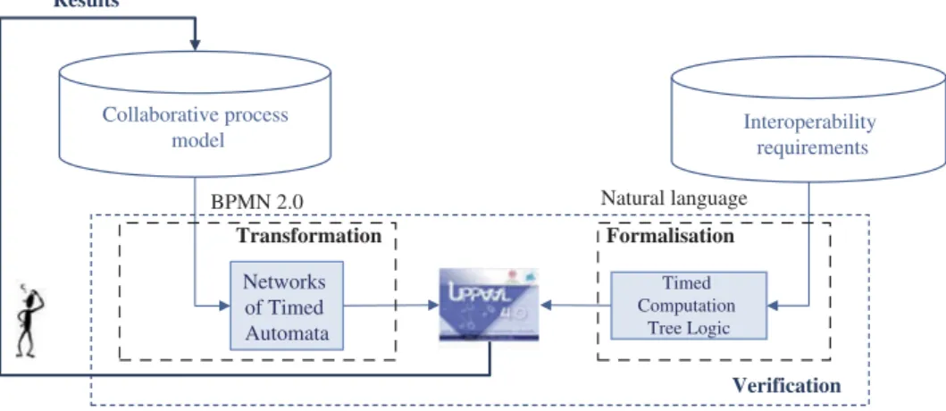
The modelling language introduced to describe the collaborative process model is BPMN 2.0 (BPMN2011); this language offers a standardised notation readily understood by all business users, from the business analysts that create the initial process drafts to the technical developers responsible for implementing the technology that will perform these processes and, finally, to the business practitioners who will manage and monitor these processes. The proposed BPMN language suffers from a lack of formalisation, and moreover the verification technique cannot be directly applied with regard to interoper-ability. As such, use of the UPPAAL model checker initially requires translating– via the model transformation rules – the collaborative process model into an equivalent model with a NTA, at which point the formal verification technique can be applied, as shown in
Figure 1. Furthermore, using test cases allows us to verify the correctness of the transla-tion from the collaborative process model into a NTA as presented in next sectransla-tion. Afterwards, interoperability requirements would need to be formalised from Natural Language into TCTL. However, to ensure the compliance and the quality of the transla-tion from Natural Language to TCTL, specific means are required and developed in other research works that are not presented in this article.
For this step, it is necessary to:
(1) Define an operational semantic based on the UPPAAL principle for BPMN elements with Timed Automata in order to generate a NTA for the studied collaborative process model. This operational semantic may exist in the literature or else determined by hypotheses that respect the desired behaviour.
(2) Translate the collaborative process model from BPMN 2.0 into a NTA using the transformation rules. The prerequisite rules for model transformation are devel-oped with ATL (Atlas Transformation Language) (ATLAS Groupe LINA & INRIA Nantes 2006) according to an automatic procedure. In this case, the transformation rules have been established and automatically implemented in respecting the equivalence between BPMN entities behaviour and state model entities behaviour.
(3) Verify that the result of this transformation is the same as both the desired and defined operational semantic. Thanks to this verification, the behaviour obtained for the collaborative process is analysed.
(4) Formalise interoperability requirements in order to enable their verification. Interoperability requirements are thus formalised with TCTL. Accordingly, it must be assumed that the BPMN 2.0 modelling language used to build the collaborative process model can also serve to describe interoperability requirements.
(5) Display the outcome of the verification technique applied to the collaborative process model (as modelled with BPMN 2.0).
(6) To be implemented, this approach relies upon a good knowledge of: (1) the UPPAAL principle; (2) the operational semantic of BPMN elements and (3) the transformation process.
Collaborative process
model Interoperability requirements
Natural language BPMN 2.0 Timed Computation Tree Logic Networks of Timed Automata Transformation Formalisation Verification Results
3. UPPAAL and BPMN principles 3.1. The UPPAAL principles
UPPAAL is a model checker for continuous time (using clock variables) designed for the verification of real-time systems. The UPPAAL tool is composed of an editor, a simulator and a verifier. The editor provides graphical interface automata to model a NTA along with a textual interface for both declarations (variables and clocks) and system evolution. The simulator allows viewing system progress in either manual or automatic mode. Lastly, the verifier component is used to verify temporal properties expressed with the TCTL temporal logic (Behrmann, David, and Larsen2004).
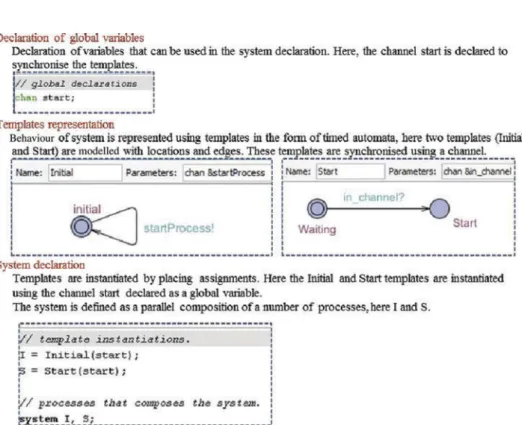
In UPPAAL, a model constitutes a set of timed automata that communicate by synchronisation through channels and an emission/reception syntax (Behrmann, David, and Larsen2004). An automaton contains states and transitions; a controller state may impose a condition on clocks, called an invariant, that must be satisfied for the entire duration spent in this state. A transition is labelled according to Behrmann, David, and Larsen (2004), i.e. guard (condition), synchronisation and update.
In this research, a set of templates is proposed to facilitate the behavioural description of a process model. Each template communicates in a synchronised manner (either in the form Expression! for sending or Expression? for receiving synchronisation) via channels and syntax such as sent/received. Moreover, a template features locations and transitions for linking a location source to a target source (Behrmann, David, and Larsen2004).
As an example,Figure 2depicts a process between two simple templates‘Initial’ and ‘Start’. These templates communicate with the ‘start’ synchronisation. In UPPAAL,
evolution of the process formed by the two templates is defined with (1) declaration of the ‘start’ synchronisation as a channel; (2) the ‘Initial’ and ‘Start’ template model in the editor and (3) the system declaration that indicates system evolution.
The UPPAAL model checker then exhaustively verifies the properties in TCTL through all feasible execution paths for the behavioural models. TCTL is an extension of CTL (Computational Tree Logic) and can be used to consider several possible futures based on the state of a given system. The UPPAAL model checker has four TCTL quantifiers (A: for all paths; E: a path exists; []: all states in a path and <>: some states in a path) and they serve to write a property p, whereby,
- E<> p: reachability (i.e. it is possible to reach a state in which p is satisfied). - A[] p: invariantly p (i.e. p is true in all reachable states).
- A<> p: inevitable p (i.e. p will inevitably become true). - E[] p: potentially always p (i.e. p is potentially always true).
- p → q: p leads to q (i.e. if p becomes true, then q will inevitably become true as well).
Figure 3, for instance, presents the verification of property E[] p, which reveals that an execution path exists where p holds for all path states. In continuing with the previous example of the two templates‘Initial’ and ‘Start’, it is now possible to verify the property ‘E[] I.initial’; this property indicates that a path exists where the Initial template is always in the‘initial’ state.
According to the UPPAAL property specification language defined above, the inter-operability requirements written in natural language are re-transcribed into properties using TCTL.
3.2. BPMN: operational semantic with UPPAAL
BPMN is a semi-formal language developed by the OMG to provide a specification for defining and representing business processes. In this context, such a formalism is applied to provide an explicit notation that is both easy-to-use and accessible to all business users. Among modelling principles, the BPMN language also offers modelling constructs adapted to business processes modelling; moreover, the reader will find in BPMN (2011) a description of the BPMN 2.0 elements used herein.
The proposed operational semantic for certain basic BPMN elements is as follows. The elements specifically considered include: tasks, resources, gateways and events. Various potential state models have been cited in the literature to represent the behaviour of a task. As an example, the Rodde Model (Rodde1989) presented inFigure 4a proposes
p p p
four states to model the behaviour of a task according to the model proposed in Trinquet (1997) and shown inFigure 4b.
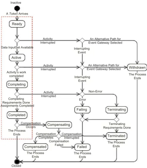
Furthermore, in BPMN 2.0, the operational semantic of an activity is determined according to the presentation inFigure 5. However, these models are rather complex in terms of state and transitions number, so that can lead to problems of combinatorial explosion when checking with the UPPAAL tool. So, by taking into account the previous existing task models (seeFigure 4), we propose an operational semantic of a Task based on 4 states that are fundamental to its behaviour, as shown on the red rectangle.
The verification technique employed however has been based on a model checker using Networks of Timed Automata to model the behaviour of the system being analysed. Some behavioural models with BPMN elements using Networks of Timed Automata can be found in the literature. For instance, Gruhn and Laue (2005) proposes the behavioural model of BPMN elements such as‘Start Event’, ‘End Event’, ‘Parallel Gateway (AND)’, ‘Exclusive Gateway (XOR)’ and the native ‘Task’ model. In another example, the behaviour of a task is represented by four locations and two synchronisations, as sum-marised inFigure 6.
Other BPMN elements (e.g. events, message flows…) are considered to be fundamental in collaborative processes; their operational semantic however does not exist in the literature; for this reason, the following section proposes developing this operational semantic.
4. Behavioural models for BPMN elements
We have developed other behavioural models corresponding to: (1) the task when a resource is involved; (2) the resource itself; (3) the inclusive gateway (OR); (4) a consideration of many inflows/outflows (including sequence and/or message flows) on both a task and intermediate time event. As mentioned previously, for each BPMN element, it is necessary to dispose a behaviour described with timed automata to make the verification possible using UPPAAL. A transformation is then defined and performed in order to obtain the behavioural model in the form of Networks of Timed Automata.
NA
W
P
IS OS
NA: Non Active W: Waiting P: Production IS: InducedStop OS: OwnStop a) Rodde model Non-operational Execution Waiting Ready Waiting for a condition Start task Stop task Occurrence of condition Pre-emption Selection Stop task Finish task b) Task model
4.1. Resource template for Task uses
The‘Task’ element in BPMN describes a work to be performed by a partner or several partners in a collaborative process. The model presented in Figure 6 describes the evolution of a task without taking into consideration any resources. It is therefore proposed to develop a Task model with a template that accounts for resource use. To this end, the model of a Task shown in Figure 6 is extended to take into account the resources consumed by a task during its execution. The timed automaton model of a task – calling a resource – is diagrammed inFigure 7.
In this model, a task is initiated with the reception of an‘in_channel?’ synchronisation type; it then sends an ‘in_resource!’ synchronisation type to use a resource and start ‘Working’. After consuming the resource within the allocated time frame, the task sends an ‘out-resource’ synchronisation type to release the resource. Afterwards, the task ends with the emission of an‘out_channel!’ synchronisation type in order to trigger the next element in the
Completing Ready Active Completed Compensated The Process Ends Closed Activity’s work completed Completing Requirements Done The Process Ends Compensation Occurs Compensation Failed Failed Terminated Terminating Withdrawn Failing Compensation Interrupted The Process Ends The Process Ends The Process Ends Terminating Requirements Done Error Interrupting Event
An Alternative Path for Event Gateway Selected
An Alternative Path for Event Gateway Selected Interrupting Event Non-Error Activity Interrupted Activity Interrupted Activity Interrupted Data InputSet Available
Inactive A Token Arrives Compensating Compensation Completes Assignments Completed
collaborative process model derived with BPMN. Let's note that this Task model can be used for all Types of Tasks: Send, Service, Manual, Business Rule, Receive, User and Script.
4.2. Resource template
The‘Resource’ element in BPMN is modelled with the corresponding timed automaton presented inFigure 8. The resource is initially available before transitioning into the active state upon receiving an ‘in_resource?’ synchronisation type from a Task. The resource
BPMN element Corresponding template
Start Event End Event Task Parallel Gateway (AND Split) Parallel Gateway (AND Join) Exclusive Gateway (XOR Split) Exclusive Gateway (XOR Join) finished working StartProcess! in_channel? in_channel? in_channel? in_channel? in_channel? in_channel? in_channel2? in_channel2? out_channel? out_channel? out_channel? out_channel! out_channel!
Figure 6. Existing template model for several BPMN elements.
Waiting Working T>=timeMax out_resource! out_channel! in_resource! in_channel? T==timeMin Start Stop
Figure 7. Task use resource template.
Available Active
in_resource? out_resource?
subsequently returns to its initial state by receipt of an ‘out_resource?’ synchronisation type once the task is finished with its use.
Let us note that this Resource model is applied to all Resource Roles, including Performer, Human Performer and Potential Owner.
4.3. Inclusive Gateway template
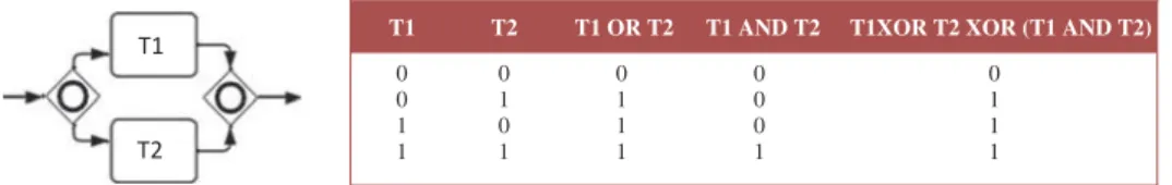
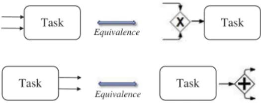
A divergent Inclusive Gateway (Inclusive Decision) can be used to create alternative, yet also parallel, paths within a process flow. Since each path is considered to be independent, all path combinations may be taken from zero to all. The Gateway should be designed however so that at least one path is taken (BPMN 2011); therefore, this element contains the operational semantic of an OR logic, except that it must be designed for at least one path to be taken (BPMN2011). To transform this element, we hypothesise that the behaviour of this element is equivalent to the link between logical operators AND and XOR, as shown inFigure 9for both activities.
Consequently, to transform the Inclusive Gateway (OR), it is proposed to establish an equivalence between the Inclusive Gateway and both the Exclusive Gateway (XOR) and Parallel Gateway (AND) models. A formal relationship between these two models is needed to model the Inclusive Gateway behaviour, as shown inFigure 10.
To generalise this use for‘N’ outputs, it is necessary to represent ‘2N’ different cases. In the Inclusive Gateway case however, at least one path must be taken into account;
T1 T2 T1 OR T2 T1 AND T2 T1XOR T2 XOR (T1 AND T2) 0 0 1 T2 T1 1 0 1 0 1 0 1 1 1 0 0 0 1 0 1 1 1
Figure 9. Interpretation of the operational semantic for the Inclusive Gateway.
Equivalence Equivalence Branching behaviour Merging behaviour T1 T2 T1 T2 T1 T2 T1 T2 T1 T2 T1 T2
therefore, we will not consider the case where an Inclusive Gateway does not advance the process (i.e. all states remain at 0). The number of feasible and mandatory cases to be modelled is thus equal to‘2N–1’.
If we were to consider the Inclusive Gateway for two outputs, a total of ‘22–1 = 3’ possible evolution cases would be found. According to Figure 10, the Inclusive Gateway triggers activity T1, activity T2 or both at the same time. As such, we model the Inclusive Gateway (OR) by an Exclusive Gateway (XOR) containing three outputs (‘T1’, ‘T2’ and ‘T1 AND T2’) and a Parallel Gateway (AND) with two outputs (‘T1’ and‘T2’). This behaviour can be generalised to N outputs of an Inclusive Gateway, with ● 2N–1: the number of outputs to be incorporated for the Exclusive Gateway (XOR);
● cP
NcPN: the number of Parallel Gateways (AND), where p is the number of Parallel Gateway (AND) outputs, with p∈ [2, N].
Figure 11depicts the construction of an Inclusive Gateway from an Exclusive Gateway and Parallel Gateway(s).
Furthermore, let us note that this generalisation is used in an identical manner when transforming an Inclusive Gateway displaying branching behaviour.
4.4. Several sequence flows on a task
In a BPMN collaborative process model, it is possible to model several Sequence Flows that either input or output on a Task. In BPMN, if several Sequence Flows input on a Task, then only one alternative is chosen. Consequently, considering several input Sequence Flows can exhibit the behaviour of an XOR operator. We thus propose simulating the existence of an Exclusive Gateway in order to represent the input of many Sequence Flows on a Task, as presented in Figure 12. By implying that a Task has multiple output Sequence Flows however, all of them will receive a signal from the Task once it reaches its finished state (BPMN 2011). We also propose simulating the
N outputs
Operators 2 3 4 N
XOR 3 7 15 2N–1
AND for 2 outputs 1 3 6
AND for 3 outputs -- 1 4
AND for 4 outputs -- -- 1
AND for i outputs -- --
--AND for N outputs -- -- -- CNN CN4 CN3 CN2
CNi
existence of a Parallel Gateway so as to represent the output of many Sequence Flows on a Task (Figure 12).
4.5. Message flows on a task
The interactions between participants in a collaborative process are modelled in BPMN using Message Flows; hence, the consideration of input or output Message Flows on a Task constitutes a prerequisite for analysing collaborative process behaviour. In addition to the existing Sequence Flows on a Task, a Message Flow must then be considered to enable process execution. Here, we propose simulating the existence of a Parallel Gateway to represent the input/output of many Flows (by taking into consideration the behaviour of the several Sequence Flows previously presented) on a Task (Figure 13).
4.6. Timer
A consideration of time is essential to the analysis of collaborative process behaviour. As such, let us propose considering the Timer that can be associated with a Start or Intermediate Event.
4.6.1. Timer Start Event
A specific time–date or specific cycle can be set to trigger the start of the Process. In this case, the Start Event must be displayed with a clock marker (BPMN 2011). It is thus proposed to translate the Timer Start Event with a template based on the Start Event template (seeFigure 6), along with a condition on a clock T like that presented inFigure 14. When clock T is equal to the Timer value, the process can then start.
Task Task
Equivalence
Task Task
Equivalence
Figure 12. Behaviour of several (input/output) sequence flows on a task.
Task Task
Equivalence
Task Task
Equivalence
4.6.2. Timer Intermediate Event
The Timer Intermediate Event acts as a delay mechanism based on a specific time–date or specific cycle. In this case, the Intermediate Event must be displayed with a clock marker (BPMN2011). The Timer Intermediate Event can be taken into consideration on the Task template by adding a clock T when starting the Task. In this case, based on the simple Task template (Figure 6) and the resource-consuming Task template (Figure 7), it is proposed to add a clock T at the beginning of the Task template in both cases, as diagrammed inFigure 15.
Moreover, let us note the non-necessity of translating the Timer Intermediate Event with a template given that its translation at the beginning of a Task model with a clock marker will suffice.
5. From BPMN to NTA
As mentioned previously, in order to verify a collaborative process model, it is necessary to translate the collaborative process model from BPMN to a NTA with respect to several hypotheses that simplify and restrict the transformation process.
5.1. Transformation process hypothesis
Several hypothesis are proposed to restrict and simplify the operational semantic of BPMN elements.
H1. The Complex Gateway does not contain an operational semantic; it will therefore not be considered.
H2. The behaviour of an Event-based Gateway is considered in the same way as an Exclusive Gateway.
H3. Both pool and lane are not involved in the operational semantic of the collabora-tive process; their representation into timed automata therefore is irrelevant. H4. A pool has at least one Start Event and one End event.
Transformation StartProcess! T==Timer Start
Figure 14. Timer Start Event template.
Task Task template with Timer
Task use Resource template with Timer Waiting Waiting Start Start Working Working Stop Stop T>timeMax T==Timer in_channel? in_channel? out_channel! out_channel! out_resource! in_resource! T==Timer T==timeMin TransformationTransformation
convergence, unless the final element of each divergent branch of the Gateway is an End Event.
These hypotheses guide the end user to model a collaborative process using the BPMN language in order to perform transformation into NTA and furthermore the verification of interoperability requirements. It is to note that some of these hypotheses are directly given by modelling rules from BPMN Standard (e.g. H4).
5.2. Transformation principle
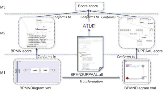
The BPMN model is transformed into NTA by means of ATL. ATL is a model transfor-mation language specified as both a meta model and a textual concrete syntax. The main advantage of using ATL is to have access to two types of model transformation descrip-tion. The preferred transformation writing style is declarative, which means that simple mappings can be expressed in simple terms; however, imperative constructs are provided so that some of the mappings too complex to be handled declaratively can still be specified. In Figure 16, the model transformation procedure (level M1) starts to take into account the meta models (level M2) of both the BPMN 2.0 language and the UPPAAL model checker, which are in conformance with the meta model Ecore (level M3) of EMF.1 Conforms to Conforms to M1 M2 BPMNDiagram.xml BPMN2UPPAAL.atl BPMNDiagram.xml BPMN.ecore UPPAAL.ecore Ecore.ecore M3 Conforms to Conforms to Conforms to Transformation
Figure 16. Transformation from an enriched version of BPMN to NTA.
H5. A Start Event does not have any incoming Sequence Flow and just a single outgoing Sequence Flow.
H6. An End Event does not have any outgoing Sequence Flow and just a single incoming Sequence Flow.
H7. A Task has at least one incoming Flow and one outgoing Flow. H8. Feedback is not considered.
H9. Collaboration between pools is performed with Message Flows.
This transformation is performed in order to provide all required templates and system declarations for the NTA. All templates are obtained by considering every modelling entity to be used during the checking task. Each class (including its attributes) and each relation of the meta model are thus translated into templates. As such, each BPMN element may be extracted from the collaborative process model, thereby producing the corresponding template that represents NTA. These templates combine all knowledge described in the model and represent the behavioural model of the collaborative process. As an example,Figure 17provides a Lazy rule with ATL to allow translating any Task into the template that features the behaviour presented inFigure 6.
5.3. Validation of the transformation
The established transformations were defined with an equivalence between the behaviour of BPMN elements – described by the operational semantic proposed above – and a timed automaton model. As a consequence, these transformations must ensure preservation of the semantic of BPMN element behaviour. Furthermore, to ensure the relevance of our
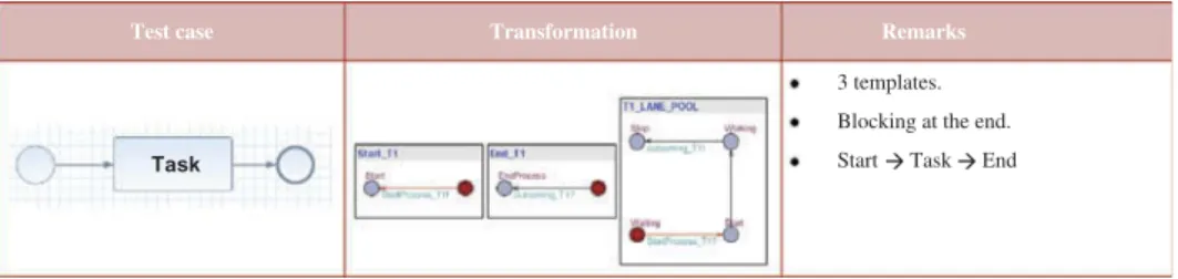
transformation as well as good representativeness of each BPMN element model with timed automata, it is proposed to introduce test cases, as shown inFigure 18with a test case of a process that contains only one start event, one task and one end event. The UPPAAL model checker offers both an editor and a simulator; the simulator offers the ability to perform tests corresponding to these test cases in order to determine whether the equivalent model of each BPMN element matches the expected behaviour with timed automata.
For this test case, the collaborative process model obtained with a NTA has been represented with three templates (i.e. one template for each BPMN element). Furthermore, the behaviour of this model is shown on the BPMN Simulator and displays the expected behaviour, such that the Start Event will begin the process with synchronisation to the Task, in sending another synchronisation to the End Event upon completion of the process.
6. Application case study
The drug circuit inside a hospital aims to more closely involve stakeholders in enhancing pharmacy practices and strengthening the role of the Medicine Committee (care unit). It has thus been proposed to analyse the behaviour of a process model describing the drug circuit by taking into account resource interoperability. A drug circuit is typically com-posed of three main steps: prescription, dispensation and administration. In order to specify the circuit's behaviour however, it is proposed to describe the main following tasks relative to the prescription step:
● Tasks performed by the pharmacy:
° Advice and analysis: the pharmacy performs a prescription analysis and offers its pharmaceutical opinion
° 5.2 Production and control: compounding, hospital preparations, reconstitu-tion of injectables…
° 5.3 Nominative delivery issue: requested in-care unit medication distribu-tion, grouped by patient
° 5.4 Global delivery issue: in-ward distribution of all drugs requested, grouped by drug
° 5.5 Supply: orders placed with suppliers in response to patient drug requests ° 5.6 Inventory: monthly (30-day) orders to suppliers, cheques and bills of
liquidation, inventory tracking… ● Tasks performed by the care unit:
° Medical prescription: the medical practitioner prescribes drugs for the patient.
Test case Transformation Remarks
3 templates. Blocking at the end. Start Task End Task
° Drug administration to the patient: the nurse administers medication to the patient in accordance with the terms of the prescription.
These Tasks and their interactions on the drug circuit have been modelled with the BPMN 2.0 modeller written in Eclipse Modelling Language, as represented inFigure 19.
The interoperability requirements (IR) chosen to illustrate this example are formulated as follows:
● IR1: ‘A human resource involved in an activity is available and able to fulfil its task or the operation assigned to it’.
● IR2: ‘The pharmacy receives supplies every 30 days’.
● IR3: ‘Nurses confirm with the pharmacy their administration of drugs to patients’. To analyse this collaborative process with regard to interoperability, it is first necessary to translate the collaborative process model with BPMN 2.0 into Networks of Timed Automata. This translation process is performed with ATL as previously demonstrated.2
In a subsequent step, interoperability requirements need to be formalised into proper-ties with TCTL. A behavioural analysis of the drug circuit can then be given on the NTA using UPPAAL.
Interoperability requirements are formalised into properties as follows. The IR1 requirement can be reformulated for the‘Medical prescription’ activity such that,
● IR1.1: ‘Medical practitioner writes medical prescription’.
● IR1.2: ‘Medical practitioner is able to write a medical prescription’.
These interoperability requirements are intended to verify that the medical prescription has been successfully written. The first requirement is formalised into a property (IP), yielding,
● IP1.1: E<> Medicalprescription_.Start and Medicalpractitioner.Available
This first property aims to verify that a path along which the Medical prescription activity is in the Starting state actually exists when the Medical practitioner is available; it can be
Opinion and analysis Medical prescription Care Unit Pharmacy Stockroom Stock Nominative delivery issue Global delivery issue Administration to the patient Supplying Production and control
verified on the behavioural model of the collaborative process derived after the transfor-mation. The second requirement however is uncorrelated with the collaborative process behaviour, and its verification can be conducted using a formal verification technique based on Conceptual Graphs (Sowa1976) with the COGITANT tool (Cogitant2009), as presented in Roque and Chapurlat (2009) and Mallek, Daclin, and Chapurlat (2012). This verification technique has not been addressed herein.
The IR2 requirement seeks to verify that the pharmacy's stock room is being supplied monthly (at 30-day intervals), i.e. every 720 hours. This requirement can then be formalised into the following property:
● IP2: E<> Supplyingstock_.Start and T> = 720
The purpose of this property is to verify that a path exists along which the ‘Supplying stock’ activity starts when T = >720 hours.
The IR3 requirement is intended to verify that when the nurse administers drugs to the patient, the pharmacy is duly informed. This requirement verifies that the‘administration to the patient’ activity is indeed performed by the Nurse, in addition to verifying that after drug administration to the patient, the pharmacist will add supply to the patient's stock. This requirement can therefore be formalised into two properties:
● IP3.1: E<> Administrationtothepatient_.Working and Nurse.Active ● IP3.2: E<> Administrationtothepatient_.Stop and Supplying_.Start
The first of these two properties verifies that a path exists along which the‘Administration to the patient’ activity is ongoing when the Nurse is active. The second property ensures existence of a path so that when the ‘Administration to the patient’ activity stops, the ‘Supply’ activity is then underway.
The verification of all properties is performed in UPPAAL, with results shown in
Figure 20.
Several properties are satisfied by the collaborative process model of the drug circuit, which has been represented as a NTA. However, the properties IP3.1 and IP3.2 are not satisfied. This result implies that, according to the drug circuit model, the interoperability requirement IR3 is not satisfied and hence an interoperability problem is detected. Indeed, this detected interoperability problem means that the Nurse may not have to administrate the drug to the patient and does not confirm it to the pharmacist. This problem can be solved, for example, by improving availability of the Nurse in order to perform the administration of the drug, and this prior to collaborative process implementation. Consequently, after the
resolution of detected interoperability problem this drug circuit is suitable for real-world implementation.
7. Conclusion
In a collaborative context, interoperability is becoming increasingly important. A partner collaborating with other partners is interested in detecting and solving interoperability problems as quickly and extensively as possible in a manner that is both adequate and efficient. In such a context, this paper focused on the use of formal verification technique to tackle this problem.
The formal verification technique used herein is based on model checking with UPPAAL, which represents the collaborative process behaviour as a NTA. This paper has proposed an analysis of the collaborative process behaviour model with regard to interoperability. More specifically, for the purpose of conducting this analysis, the ver-ification technique employed has relied on model checking via UPPAAL. To enable verification with this technique, it was first necessary to translate the targeted collabora-tive process model from BPMN to a NTA. This translation step was performed using model transformation language with ATL. The second step entailed formalising interoper-ability requirements into properties with TCTL.
This approach however revealed several limitations. The first of these relates to the selected model checking technique. Model checking is based on an exploration of all feasible paths or behaviours of a system; moreover, it allows taking the temporal aspect into account. Such a verification technique is still limited by the problem of a combinatorial explosion in the number of states, hence paths, that may eventually appear. This limitation causes, in the best case, the verification to be slowed and, at worst, the inability to generate tangible proof; in addition, it can result in the inability to verify interoperability require-ments. Accordingly, it is proposed herein to study model partitioning mechanisms in order to raise this issue during subsequent works. Another limitation in the approach tied to the verification technique adopted pertains to the verification outcome being solely based on a true or false response. An interoperability problem is in fact detected whenever the inter-operability requirement is not being satisfied by the collaborative process model. It would be advised to graduate the possible responses and therefore not be limited to one type of response like‘true or false’. Failure to meet a single requirement does not imply that the process is not interoperable. The third limitation relates to the formalisation of interoper-ability requirements into properties. This approach is in fact limited to formalising inter-operability requirements into properties directly on TCTL; yet, it remains difficult to ensure compliance and the quality of expression of every given property. In addition, the user must demonstrate an explicit mastery of the property representation language (TCTL). As such, it is proposed to use the Semantic Business Vocabulary and Business Rules (SBVR) (OMG
2008), which offers a vocabulary for writing interoperability requirements into natural language; in this manner, it will be possible for automatic translation into TCTL using the transformation model with ATL. Lastly, this approach is limited to detecting interoper-ability problems without providing solutions to these problems. Consequently, future research will be aimed at finding solutions for the interoperability problems detected. It is proposed herein to embrace interoperability approaches such as integrated, unification and federation approaches (INTEROP 2006) in order to develop solutions to these detected interoperability problems and to improve the collaboration.
Notes
1. Eclipse Modelling Framework, available online at:http://www.eclipse.org/modeling/emf/ 2. The results of this transformation are available at: http://www.lgi2p.ema.fr/~chapurla/
interoperability/
References
Alur, R., C. Courcoubetis, and D. Dill. 1993.“Model-Checking in Dense Real-Time.” Information and Computation 104 (1): 2–34.
ATLAS Groupe LINA & INRIA Nantes. 2006. “ATL: ATlas Transformation Language, ATL User Manual”, version 0.7. Accessed January 13 2014. HYPERLINK “http://www.uio.no/studier/emner/ matnat/ifi/INF5120/v06/undervisningsmateriale/ATL_User_Manual%5bv0.7%5d.doc” http://www. uio.no/studier/emner/matnat/ifi/INF5120/v06/undervisningsmateriale/ATL_User_Manual[v0.7].doc Aubert, B., and A. Dussart. 2002. “Système d’Information Inter-Organizationnel.” [In French.]
Rapport Bourgogne, Groupe CIRANO, March.
Balci, O., and W. Ornwsby. 2002. “Expanding Our Horizons in Verification, Validation and Accreditation Research and Practice.” Proceedings of the 2002 Winter Simulation Conference, vol. 1, edited by E. Yücesan, C.-H. Chen, J. L. Snowdon, and J. M. Charnes, 653–663, San Diego, CA, December 8–11.
Behrmann, G., A. David, and K. G. Larsen. 2004. A Tutorial on UPPAAL. Aalborg: Department of Computer Science, Aalborg University.
Bérard, B., M. Bidoit, A. Finkel, F. Laroussinie, A. Petit, L. Petrucci, Ph. Schnoebelen, and P. McKenzie. 2001. Systems and Software Verification: Model Checking Techniques and Tools. Berlin: Springer. BPMN. 2011. Business Process Modeling Notation, V2.0.http://www.bpmn.org/
Cogitant. 2009. CoGITaNT Version 5.2.0, Reference Manual.http://cogitant.sourceforge.net Department of Defense. 2003. Standard Practice Defense and Program-Unique Specification Format
and Content. MIL-STD-961E, 1 aout, 99. August 1. http://www.navair.navy.mil/nawctsd/ Resources/Library/Acqguide/mil-std-961e.pdf
Duffy, D. A. 1991. Principles of Automated Theorem Proving. New York: John Wiley & Sons. Clarke Jr., E. M., O. Grumbereg, and A. P. Doron. 1999. Model Checking. Cambridge, MA: MIT
Press.
Gruhn, V., and R. Laue. 2005. “Using Timed Model Checking for Verifying Workflows.” In Proceedings of the 2nd International Workshop on Computer Supported Activity Coordination, CSAC 2005, edited by J. Cordeiro and J. Filipe, 75–88, May. Miami, FL: INSTICC Press. INTEROP. 2006. Report on Model Interoperability, Deliverable DTG 2.2, Version 1.9, 94 p. June
29.http://interop-vlab.eu/ei_public_deliverables/interop-noe-deliverables
INTEROP. 2007. Enterprise Interoperability-Framework and Knowledge Corpus– Final Report. INTEROP NoE, FP6–Contract No 508011, Deliverable DI.3, Final Version, 44 p. May 21. http://interop-vlab.eu/ei_public_deliverables/interop-noe-deliverables
ISO. 1994. 8402, Quality Management and Quality Assurance. Vocabulary. 2nd ed. Geneva: International Standard Organization.
ISO/DIS. 2009. 11345-1: Advanced Automation Technologies and Their Applications. Part 1: Framework for Enterprise Interoperability, 40. ISO/TC 184/SC 5. Geneva: International Organization for Standardization.
Mallek, S., N. Daclin, and V. Chapurlat. 2012.“The Application of Interoperability Requirement Specification and Verification to Collaborative Processes in Industry.” Computational Industry. doi:10.1016/j.compind.2012.03.002
Mallek, S., N. Daclin, V. Chapurlat, and B. Vallespir. 2013. “Requirements Formalization for Systems Engineering: An Approach for Interoperability Analysis in Collaborative Process Model.” Workshop on selected applications and methods for enterprise interoperability, co-located with the 5th International IFIP Working Conference on Enterprise Interoperability (IWEI 2013), Enschede, March 26.
OMG. 2008. Available Specification, Semantics of Business Vocabulary and Business Rules (SBVR), v1.0.http://www.omg.org/spec/SBVR/1.0/PDF
Rodde, G. 1989. Les systèmes de production : modélisation et performances, 330 p. [In French.] Paris: Hermes Sciences Publication.
Roque, M., and V. Chapurlat. 2009. “Interoperability in Collaborative Processes: Requirements Characterisation and Proof Approach.” PRO-VE’09, 10th IFIP Working Conference on VIRTUAL ENTERPRISES, Thessaloniki, October 7–9.
Sowa, J. F. 1976.“Conceptual Graphs for a Data Base Interface.” IBM Journal of Research and Development 20 (4): 336–357.
Trinquet, Y. 1997.“Un aperçu sur quelques exécutifs temps réel du marché.” [In French.] Ecole d’été, Temps Réel’97 Applications, Réseaux et Systèmes.
Zeigler, B., T. G. Kim, and H. Praehofer. 2000. Theory of Modeling and Simulation. New York: Academic Press.