HAL Id: hal-02320841
https://hal-mines-albi.archives-ouvertes.fr/hal-02320841
Submitted on 8 Sep 2020
HAL is a multi-disciplinary open access
archive for the deposit and dissemination of
sci-entific research documents, whether they are
pub-lished or not. The documents may come from
teaching and research institutions in France or
abroad, or from public or private research centers.
L’archive ouverte pluridisciplinaire HAL, est
destinée au dépôt et à la diffusion de documents
scientifiques de niveau recherche, publiés ou non,
émanant des établissements d’enseignement et de
recherche français ou étrangers, des laboratoires
publics ou privés.
The impact of the casting thickness on the interfacial
heat transfer and solidification of the casting during
permanent mold casting of an A356 alloy
Anwar Hamasaiid, Matthew Dargusch, Gilles Dour
To cite this version:
Anwar Hamasaiid, Matthew Dargusch, Gilles Dour. The impact of the casting thickness on the
interfacial heat transfer and solidification of the casting during permanent mold casting of an A356
alloy. Journal of Manufacturing Processes, Society of Manufacturing Engineers, 2019, 47, pp.229-237.
�10.1016/j.jmapro.2019.09.039�. �hal-02320841�
The impact of the casting thickness on the interfacial heat transfer and
solidification of the casting during permanent mold casting of an A356 alloy
A. Hamasaiid
a,b,c,d,⁎, M.S. Dargusch
b, G. Dour
a,eaEcole des Mines d'Albi-Carmaux, CROMeP, now Institute Clement Ader, 81013, Albi Cedex 09, France
bCentre for Advanced Materials Processing and Manufacturing, School of Mechanical and Mining Engineering, The University of Queensland, St. Lucia, Brisbane, QLD,
4072, Australia
cUniversité Paul Sabatier, 118, Route de Narbonne, 31062, Toulouse Cedex, France dnow at 3DmetDie, France
enow at Advisian/WorleyParsons group, 600 Murray Street, 6005, West Perth, Australia
Keywords:
Permanent mold casting Gravity die casting Heat transfer Coating A356 alloy
A B S T R A C T
Many important quality indicators for components manufactured using permanent mould casting, such as the presence of shrinkage porosity, microstructure features, dimensional stability, cycle time and filling mechanisms are controlled directly or indirectly by the heat transfer mechanisms linking the casting to the mould. While interfacial heat transfer in permanent mould casting has been significantly investigated and widely reported in the literature, the geometrical dependence of heat transfer parameters has not been studied or reported in detail. Understanding this dependency is very important as the same cast component most often is constituted by different sections and geometrical variations. In this paper, experimental methods and analytical correlations have been developed and presented that enable an accurate determination of the time dependent interfacial heat flux density and heat transfer coefficient at the casting-mould interface. The variation of these parameters is investigated and analysed for three different casting sections and two types of thermal barrier coatings.
1. Introduction
Permanent Mould Casting (PMC), also called gravity die casting, of aluminium alloys is currently used to produce many components for many industrial sectors, in particular the power train components of automobiles, including the engine block and related components such as cylinder heads, and many other parts requiring high mechanical properties. The process consists of pouring aluminium liquid into a metallic mould that has a cavity shape required for the component to be produced. PMC moulds are generally made of hot work tool steels (type 1.2344 (AISI H13) or 1.2343 (AISI H11). These types of tool steels are used for their dimensional stability and high mechanical strength at elevated temperatures along with good toughness and resistance to thermal shock and thermomechanical fatigue.
Prior to pouring the mould cavity with molten aluminium alloy, the mould cavity surface is coated with a ceramic or graphite-based coating. The coating layer (50–200μm thick) has several functions in order to facilitate the removal of the castings after solidification, pro-tecting the surface of the mould and preventing adhesion of the alu-minium alloy to the surface of the mould along with control of the
solidification pattern [1]. The die also should be heated up to 100 °C–200 °C to avoid thermal shock and fracture along with pre-venting the premature solidification of the aluminium alloy before the filling is complete. Then the aluminium is poured into the die at around 700 °C [2]. When the die is filled, the component starts to solidify by removing the heat from the liquid alloy, via the die-component-inter-face through the die section influenced by the cooling medium. The cooling system is generally composed of a network of channels em-bedded into the die body at optimised distances, generally 15 mm–30 mm from the die surface, to avoid catastrophic cracks from the cooling line surface to the mould surface. Generally, a liquid or air is circulated inside the cooling lines to transport the heat outside of the system. The cooling of the component continues until solidification is complete. Then the die is opened and the solidified components are removed and the next cycle is started.
One of the most important factors in this process is the heat transfer during the solidification of the molten alloys. This is because the re-sulting microstructure, on which the quality of the cast piece is based, and the cycle time depends on the dynamics of the heat transfer [3]. Higher heat transfer results in finer microstructure and higher
⁎Corresponding author at: Ecole des Mines d'Albi-Carmaux, CROMeP, now Institute Clement Ader, 81013, Albi Cedex 09, France.
mechanical properties such as yield and impact strength [4]. Higher heat transfer results in shorter cycle times. Close control of the heat transfer at different areas of the cavity during the solidification pro-cesses is required in order to prevent shrinkage porosity and ensure proper control of the contraction dynamics during solidification.
Heat transfer in PMC is governed by different medium with geo-metric features of different complexity [1–5]. The governing factors and related interfaces are 1) through the solidified casting layer toward the cast/mould interface, 2) the coating compositions and thicknesses, 3) the mould material thermal conductivity along with the mould’s design and configuration and 4) the cooling systems. The heat transfer is generally characterised by the interfacial heat transfer coefficient (IHTC)
One of the major difficulties in simulating the PMC process is the lack of understanding of the heat transfer mechanism ant their impacts on IHTC associated with each of the above mentioned medium that directly influences the results of the simulation processes and the in-terpretation of the outcomes of these simulations and how these out-comes relate to the properties of a casting of a given geometry including the development of shrinkage and air porosity defects, optimising the runner and gating systems, and optimising the dimensional tolerances and the solidification pattern and time.
Considering the impact of IHTC in PMC, understanding the me-chanism of these important parameters has become an important issue for researchers and industry over the last four decades. The authors of the references [6,7]. studied the heat extraction through the die wall assuming that the casting-die interface has no resistance to heat flow (IHTC= ∞) in order to simplify the analytical treatment of this pro-blem. However, Prates et al. [8] reported that this hypothesis is not applicable in the case of the formation of a chill zone. They stated that a thermal resistance exists at the metal-die interface that limits the heat transfer during solidification. The thermal resistance is the inverse of the IHTC. Since this foundation work, many analytical and empirical methods have been developed to determine the IHTC such as using semi-analytical methods based on empirical correlations [9–13]. But using numerical methods based on the Beck iteration inverse method [14] using the experimental temperature data to determine the IHTC has gained popularity. Almost all the studies that have been reported on IHTC in PMC have used and optimised the analytical, numerical and experimental methods to improve the accuracy in the determined va-lues of IHTC [15–19]. The authors of the present paper have further improved the accuracy of the determination of the IHTC in previous published work. In this study the optimised method which is reported [1] is used to accurately determine the IHTC.
With regard to the impact of the process parameters, Most of the published work, deals with the interface conditions and the geometrical parameters on the mould side, such as surface condition ([20,21], gap formation between the casting and the mould surface [22] mould thickness [23–25], casting composition [23]. There is no literature available on the impact of casting thickness. Furthermore, Guo et al. [26] studied the influence on casting thickness on IHTC for High Pressure Die Casting Process (HPDC). They stated that while the process
parameters, such as injection velocity and initial die temperature in-fluence the peak value of IHTC, the casting thickness does not. In a previous study of the present authors the impact of the coating com-position and thickness has been highlighted [1]. The work that will be presented in this paper studies the effect of the casting thickness on the IHTC for PMC.
2. Experimental method 2.1. Casting procedure
In order to study the effect of the casting thickness on the heat transfer at the casting-die interface in PMC, a mould has been designed and manufactured from EN/DIN 1.2344 (AISI H13) steel and heat treated to a hardness level of 42–44 HRc. The chemical composition of the mould is shown inTable 1. The mould consists of two halves with original dimensions 210 × 210 × 50 mm for each half. The fixed half is a simple block of steel, whilst the mobile half has been machined to incorporate a 110 x 110 mm cavity with variable thicknesses. This variation of the thickness was produced by making steel blocks, with different thicknesses. The blocks were designed and manufactured to be easily inserted by sliding into the rear side of the mobile half of the die. This has allowed castings to be produced with three different widths (15 mm, 20 mm and 25 mm). These inserts were also cost effective and provided an effective mechanism for maintaining the same basic mould metal filling characteristics for different casting thicknesses.
The castings have been produced using a pilot machine, which has been built to run the die in a productive manner. The closing and opening movement of the mould was facilitated by a pneumatic pump. Two main series of experimental trials were performed while casting the Al-7Si-0.3 Mg alloy (A56) with different thicknesses. The chemical compositions of the investigated alloys are shown in
Table 2The alloy was melted in an electrical resistance furnace to 750 °C and it was poured manually into the die cavity using a pre-he-ated ladle. During the first series of castings, a white coating (TiO2
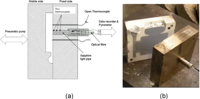
based with silicate binder) was applied to the die and during the second series, a graphite coating was used. The coating was sprayed with a pressure of 4 bar, by an established manual spray technique, onto the cavity surface, which was preheated to about 200–210 °C prior to the application of the coating. The thickness of the coating was measured and controlled by an Erichsen probe (MiniTest2100). This was done in order to keep the coating conditions comparable for each casting cycle and eliminate the effect of a thickness variation, as described in a previous publication by the current authors in [1]. For each casting thickness, several castings were produced for the purpose of reprodu-cibility.Fig. 1a shows a top view cross section schematic of the closed mould that had been instrumented with an advanced specially devel-oped sensors develdevel-oped and optimised by the authors of the present paper, [1,27,28] to measure the temperatures inside the die and the component surface. It is detailed in the following sectionFig. 1b which shows the real mould opened after a casting cycle.
Table 1
Chemical composition of X38CrMoV-5 steel (EN/DIN 1.2344, AISI H13).
Element % C Mn Si S P Cr Mo V Fe
X38CrMoV-5 0.396 0.36 0.94 < 0.003 0.009 5.05 1.25 0.47 balance
Table 2
Chemical composition of Al-7Si-0.3 Mg alloy.
Alloys Cu Zn Si Fe Ti Ni Mn Mg Pb Sn
2.2. Temperature measurements
For the temperature measurement an advanced sensor had been designed, machined, mounted and calibrated using the guidelines pre-sented in references [1,27,28]. The sensor was fabricated from the same steel as the mould. Respecting the isothermal, heat flux direction, six thermocouples (type K) were installed at three different positions: 1 mm, 10 mm, and 20 mm below the active sensor surfaces. These thermocouples are paired for redundancy. The K-Type thermocouples have the diameters of 0.25 mm and they are inserted into the sensor as previously described in detail [27,28] in order to ensure the fastest response time possible and taking representative temperature values. The fixed half of the die was modified to insert the sensor at the centre of the cavity as illustrated inFig. 1, with the active surface of the sensor remaining flush with the surface of the die. In this way, the active surface of the sensor is part of the die cavity surface and the tempera-tures beneath the die surface are the same as what is measured by the sensor.
The alloy surface temperature is measured using two open ther-mocouples. Two holes with diameter of 2 mm were drilled 15 mm to the left and to the right of the gauge position, in the centre of the cavity. Two Chromel and Alumel wires, of 0.25 mm diameters, were inserted into two-hole ceramic rods, themselves located in the holes of the die. The wires were inserted 1 mm into the die cavity, as illustrated in
Fig. 1a. The casting surface temperature was then provided by the hot junction produced by the aluminium.
The acquisition of temperature data was via a computer-controlled system developed with LabVIEW particularly for this purpose of these experimental trials.
3. Results and discussion 3.1. Raw temperature data
Fig. 2shows the results of the temperature measurements for the three casting thicknesses. The curves marked with a circle, triangle and square correspond to the temperatures measured for the casting thick-nesses of 15 mm, 20 mm and 25 mm respectively. As can be seen from the curves of the alloy surface temperature, the liquid aluminium temperature is at around 645–650 °C when it arrives at the location of
the sensor in the cavity. That is to say, the molten alloy has lost about 125 °C in the ladle and sprue section of the mould before arriving at the temperature sensor location in the cavity. The alloy surface tempera-ture then falls down rapidly to under liquidus temperatempera-ture (613 °C) for all three casting sections almost at the same time. Then the curves present the first stage of the process with a moderate decrease until around 580 °C. The moderate decrease is observed to be faster and shorter for the thinner sections. After this stage, the temperature stays almost steady at about 580 °C for periods that clearly depend on the casting thickness. Considering the eventual error in the exact tem-perature measurements, the plateau at 580 °C corresponds to the soli-dification of the eutectic Al-Si. Below this point, the melt alloy surface temperature drops rapidly, signalling that solidification at the surface of the casting was complete. The interval between the liquidus and the eutectic (end of solidification) increases proportionally with casting thickness namely 35 s, 50 s and 65 s respectively for the 15 mm, 20 mm and 25 mm thickness sections.
Fig. 1. a) Top view cross section of the die instrumented with heat transfer sensor and open thermocouples and the schematic of the experimental set up and b) illustration of a casting that was produced.
Fig. 2. Measured temperature data for three different casting thicknesses (White coating, pouring temperature 750 °C).
The temperatures at 1 mm beneath the surface of the mould rises to reach up to 376 °C, 384 °C and 401 °C respectively for the 15 mm, 20 mm and 25 mm casting thicknesses, from the initial value of about 280 °C. These temperatures are obtained when the melt alloy tem-perature reaches the eutectic temtem-perature (576–580 °C). Afterwards, the temperatures at the depth of 1 mm (TC(1 mm)) drop slightly for periods that depend on the casting sections namely 4 s, 9 s and 14 s respectively for the 15 mm, 20 mm and 25 mm sections. After this period of temperature decrease, the TC (1 mm) rises up again to reach a second peak when the melt alloy surface temperature is close to the solidus temperature. When the alloy surface temperature falls below the solidus temperature, the curves of the TC (1 mm) fall also with intensity that depends on the casting section thickness. As a general rule, the thinner the casting section is, the faster the fall of the mould near-surface temperature.
The rise of the temperature curves at 10 mm and 20 mm (TC (10 mm) and TC (20 mm)) was triggered with a slight delay of 2.5 s and 5 s respectively, as expected with the diffusion of the heat through the die. In all three investigated casting sections, the delay is the same. One can observe that when TC (1 mm)) starts to fall, the TC (10 mm) and TC (20 mm)) continue to rise for a while signalling the continuity of the heat diffusion mechanism (delay and damping effect). The effect of the solidification of the eutectic in the casting (secondary peak) is less marked in the variation of temperature at 10 mm and 20 mm as the readings at these distances are less sensitive to the short-lived heat transfer fluctuations at the casting-die interface.
3.2. Determining interfacial heat flux and heat transfer coefficient The temperature data measured at 1 mm and at 20 mm have been analysed using an inverse method based on Beck’s iterative method to evaluate the interfacial heat flux density (Wm−2) at the mould-casting
interface [14–29]. From the evaluated interfacial heat flux density, the temperature of the mould surface is determined by a direct method using the heat flux density as an input and the temperature at each position 1 mm, 10 mm and 20 mm is evaluated as a function of time and compared to the recorded temperatures. The predicted temperature at 10 mm must agree within ± 10 °C over the whole cycle before the IM evaluation is considered acceptable. The detail of this IM method has been described in detail in previous work by the current authors [2,9,10].
Fig. 3shows the heat flux and IHTC at the casting-mould interface for different casting thicknesses for the white coated mould, while
Fig. 4shows the heat flux and IHTC for the graphite coated mould. The curves of heat flux density and IHTC presented inFigs. 3 and 4
show a rapid rise during the first 1 s to reach their peak values. The peak values of the interfacial heat flux density and IHTC are similar for the different casting thicknesses. They are also similar for the castings produced with two different coating compositions of comparable thicknesses. These results were found to be reproducible for each trial performed. The peak values of the determined IHTC are also compar-able to the values reported in the literature for example in the following references [1–5,15–19].
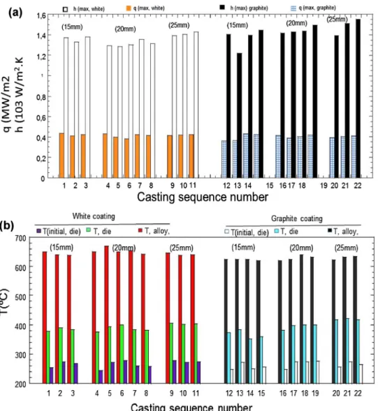
Fig. 5(a) and (b) show the maximum values of heat flux density and IHTC for the different die coating types and conditions investigated. The small scatter between the peak values of IHTC and heat flux density can be related to the small difference in coating thickness between different trials. One can also observe that the peak values of IHTC for the trials performed with the graphite coating are slightly greater than that of those performed with the white coating for some cycles. That is probably due to the fact that when the coating thickness is around 100μm, the effective conductivity of the graphite coating is slightly greater than that of the white coating [1,30]. It is also probable that the liquid alloy wets the surface of the graphite coating better.
However, the evolution of heat flux and IHTC at the casting-mould interface are not similar. In general, four different stages in the varia-tion of these parameters can be identified as follows:
1 The heat flux density decreases moderately, at the same slope for the three casting thicknesses, but for periods of time that seem to be dependent on the casting thickness. The thinner the casting, the shorter this period, as can be seen inFigs. 3 and 4. At this stage, the IHTC curves (Figs. 3(a) and4(b)) present and follow a plateau at their maximum value. The maximum values of IHTC for the three casting thickness are close to be comparable with a small tendency towards lower values for thinner castings. However, the period of that step seems to be proportional to the casting thickness. 2 In the second stage the heat flux density and IHTC decrease rapidly,
the slope of the decrease seems to be faster for thinner castings. This second phase of heat flux coincides with the beginning of the eu-tectic plateau.
3 The curves of the heat flux density and IHTC rises moderately
towards the value of the second peak. The time at which this third stage occurs appears to be proportional to the casting thickness. The magnitude of the second peak seems to be larger for the castings produced with a graphite coating on the mould. This phenomenon has been discussed in detail in the previous paper of the authors of this article [1] but there are no clear trends with casting thickness present. The duration of this stage doesn’t seem to vary with casting thickness. It is around 20 s for both coatings.
4 The IHTC and heat flux decrease towards zero. In this stage the values for the heat flux and IHTC curves seem to be independent of the casting thickness and coating composition.
4. Discussion
The first increase in heat flux density and IHTC does not have any important physical meaning. It is determined by the time during which the liquid alloy arrives near the region of the cavity where the IHTC gauge is located and by the response time of the thermocouples.
One of the most interesting findings in this work is the evolution of the first peak in each of the IHTC curves as a function of the casting thickness which is observed inFigs. 3(b) and4(b). As can be seen the casting thickness has no influence on the peak value of both heat flux density and the IHTC. However, the duration during over which the IHTC is maintained is larger for the thicker castings. If one compares the curves inFig. 3(b) (IHTC) and inFig. 2(temperature) for the same time periods, knowing that they were plotted from the same sets of tests, one can note that the periods of the first peak and associated plateau regions correspond to the period during which the temperature of the alloy is above the eutectic temperature (seeFig. 1). The periods of the first fall and the second rise correspond to the formation of the eutectic phase and the final drop in IHTC curves corresponds to the cooling of the fully solid skin (below the eutectic). This final drop is due to an air gap generated by the thermal contraction of the now solid casting.
Close examination of the results allowed the authors to understand that the peak value is uniquely due to the parameters that construct the interface conditions, mostly pressure, surface roughness, contacting surface microstructures and the harmonic thermal conductivity which is derived from both the thermal conductivity of the mould and casting material by the following equation:
λs= 2λmλc/ (λm+λc) (1)
Where λm and λc are the thermal conductivities of the mould and
casting respectively.
The casting thickness is not a parameter of the interface. The slight increase of the peaks of IHTC as the function of casting thickness ob-served on theFigs. 3(b) and4(b) is eventually related to the increase of metallostatic pressure due the increase in casting volume for the larger thickness castings.
These reproducible correlations between the evolution of the alloy temperature and HTC underline the fact that the interface properties can be expected to change as phase changes occur in the alloy during solidification.Fig. 6is a plot of the IHTC versus the measured surface temperature, which further depicts the relationship (note the curve for 20 mm casting seems to be shifted 6–7 °C compared to the alloy eu-tectic).
Based onFig. 6 and the previous discussion, the evolution of the IHTC with temperature can be divided into three main stages in terms of casting-die contact conditions which corresponds to the major stages of solidification during casting of this alloy.
4.1. Liquid-solid contact
During the liquid-solid contact stage (above 620 °C) the IHTC re-mains fairly constant at its maximum value forming a plateau. The peak value of the IHTC in this stage is expected to depend on the coating thickness, coating surface conditions, alloy composition through its conductivity, surface tension and metallostatic pressure. Based on the experimental observations, the peak value of the IHTC is independent of the casting volume and largely independent of the type of coating. The small scatter seen in the data summarised inFig. 5between the peak values of IHTC and heat flux density in this stage is in fact related to the small difference in coating thickness and an eventual variation of metallostatic pressure between different trials and the effective coating conductivity (influenced by the coating application and resulting voids density). The peak values of IHTC for the trials performed with the graphite coating are slightly greater than the peak values obtained with the white coating for some cycles for the reason discussed in the pre-ceding pages.
4.2. Semisolid-solid contact
The plateau continues below the liquidus as depicted inFig. 6. The temperatures at which the IHTC starts dropping is close to 590 °C for the 15 mm thick casting and closer to 580 °C for the thicker castings. When applying the Scheil-Gulliver model for a typical 7% Al-Si alloys, these two temperatures would correspond to a solid fraction of 45% and 55%. This is still much lower than the coherency condition of 80% solid fraction for the stress build-up. However, the dendrite network must have a sufficient gelatine-like cohesion to contract and loosen the in-terfacial contact. The dependency of the first drops in IHTC on the casting section means that the solidification does not happen layer by layer with a marked solid front from the beginning. It could mean that the contact deteriorates when a certain amount of solid fraction in the total volume of the casting is developed. Hence for the larger casting section the time needed for the solid fraction to reach such an amount seems to be larger for the same peak value of IHTC and heat flux density.
Fig. 7shows the period of the initial plateau of IHTC and the period of temperature of the aluminium alloys above eutectic temperature as a function of casting thickness for the number of casting cycles. It is in-teresting to observe that the period of the initial plateau in the variation of IHTC corresponds exactly to the period during which the alloy is
Fig. 5. (a): Summary of peak values of heat flux density and IHTC at the casting-mould interface for different casting thicknesses and different coating types. (b): Peak values of alloy and die surface temperature and initial die temperature for three series of cycles performed with three different casting thicknesses (15 mm, 20 mm and 25 mm).
totally liquid. This period is in general smaller by 5 s for the obtained curve with the graphite coating than that obtained with the white coating for the reasons discussed above.Fig. 7shows that this period increases linearly at a rate of 15 s when the casting thickness increases by 10 mm for both data series (graphite and TiO2). As this initial peak/
plateau period corresponds to the time for which the alloy remains up to 55% liquid, it can be expected that its duration should also depend on alloy composition, pouring temperature and the properties of the die. If a linear fit of the data inFig. 7is performed it can be seen that the slopes of the two produced lines are lightly different. This period (thmax)
for IHTC as a function of casting thickness (ec) can be characterised by
the Eq.(2)for white coating and Eq.(3)for the graphite coating for the reported experimental.
thmax=-10 + 1767ec (2)
thmax= -18 + 1866ec (3)
It is expected that this period is influenced also by the intensity of cooling, coating thickness, alloy composition, applied pressure or me-tallostatic pressure. Further investigation is required in order to model the dependency of this period on the above-mentioned parameter for a giving alloy and mould material.
The rate of the decrease is also related to the casting section thickness as can be seen inFig. 8. This can be related to the rate of change in solid fraction, which would be faster in thin castings than in thicker castings. As can be seen, the slope (m) of the curves increase when the casting thickness decrease. However, the increase is not linear. This drop depends directly on the kinetic of solidification which is derived by the alloy composition and all the parameters discussed above that determine the IHTC and the cooling rate.
After the drop and a minimum at the eutectic temperature as de-picted inFig. 6by the denser number of points in the plot, the IHTC (and also the heat flux density) presents a second peak. The impact of this increase in heat transfer is also reflected in the mould surface temperature (see Fig. 2), which slightly increases with a delay. Close examination of the second peaks for all casting cycles performed shows that the magnitude of the second peak seems to be independent of the casting thickness. These second peaks occur erratically and even some large differences can be observed for a few cycles performed under the same casting conditions. In general castings produced with graphite coatings were associated with larger values for the second peak in both the IHTC and heat flux.
The causes of the second peak may be linked to either of the fol-lowing:
- Expansion of the casting when the solid Si phase forms; this starts at the eutectic and continues afterwards. Such expansion of the casting was also noted in Wilhelmy tests performed independently [31]. - Exudation of liquid towards the surface; below the eutectic, the solid
fraction near the casting-mould surface is sufficient for the casting to thermally shrink, but there could be enough liquid channels re-maining open to permit the residual liquid in the centre to force its way through, under metallostatic pressure. The fresh contact of li-quid with the mould surface decreases thermal resistance, leading to a second increased IHTC, and hence increased heat flux and local mould temperature. Such exudation has been reported previously. - Recalescence; when delayed by nucleation undercooling
solidifica-tion takes place rapidly and the energy released by the exothermic process leads to an increase in temperature. The higher casting temperature then leads to an increased IHTC. This was noted in [2] as a potential explanation of the second peak in heat flux density and mould temperature.
The absence of increasing temperature (see Figs. 1 and 6) in the casting eliminates the scenario of recalescence. The variability and the random occurrence of the second peak tends to suggest that exudation could be the leading mechanism, given the complexity of the me-chanism leading to it. This was also the argument noted in Reference [32] to explain random occurrences of secondary peaks.
The slow build up to the second peak implies that the exudation is itself slow, or else it occurs over time in numerous places on a very small scale.
4.3. Solid-solid contact
This condition of contact starts when solidification is complete or has reached the coherency temperature across the whole casting thickness. At this stage the surface temperature of the casting is below the eutectic.
Due to the cooling, the casting contracts and the contact conditions drastically deteriorate. At some stage, the casting and the die coating depart contact and an air gap forms. As a consequence, IHTC drops continuously and tends towards very low values. The IHTC is uniquely dominated by the air gap in this stage as it is also been reported else-where in references [5,32].Fig. 6shows that the thicker castings have a
Fig. 7. Period of first plateau (liquid-solid) of the IHTC vs. casting thickness.
lower IHTC at any given temperature. This is because the gap δ is proportional to the thickness of the casting (e) at a given temperature, as per Eq.(1).
δ = e. α. ΔT (4)
Whereα is the thermal contraction coefficient
ΔT is the variation of temperature from the initiation of the air gap However, the final drop in IHTC seems to be slower for thicker castings (seeFig. 3 and 4). This is because the thicker castings show a slower variation of temperature with time in this stage as shown in
Fig. 2.
In casting simulations, the heat transfer coefficient is usually taken as a unique function of the temperature, regardless of the casting thickness. The heat transfer is typically taken as a high dwell, followed by a drop to zero at a fixed temperature. AsFig. 6shows this is not correct, and the drop-temperature has to be made thickness specific as inFig. 7. Moreover, the drop is not infinite andFig. 8should be used to linearize it. This would potentially improve the accuracy of detecting the time for which the mould is closed along with improving the de-tection of the cooling profile and optimising by integrating the local cooling intensity. In addition, the semi-solid period is simplified in re-ported simulation work as a vertical drop, this work shows that the initial drop is faster for thinner castings. Even if the phenomena of recalescence discussed above complicates the interpretation of this period it is clear that the findings presented here show that the varia-tion of the initial slope (Fig. 8) as a function of casting thickness for the period associated with the steep vertical drop could improve the ac-curacy of the simulation outcomes.
5. Conclusion
The advanced experimental instrument and procedure presented in this paper have enabled the study of the impact of the casting thickness on the interfacial heat transfer during permanent mould casting of the A356 aluminium alloy. The underlying mechanisms which may explain the variation of the heat flux density, interfacial heat transfer coeffi-cient, temperature of the mould surface and melt alloy surface have been discussed for the difference stages of the casting process.
The main findings are listed below:
- The heat transfer coefficient at the casting-mould interface changes with time, as a result of the different state of matter and natural expansion/contraction of the casting during the solidification pro-cess.
- The casting thickness does not influence peak values or intermediate values of the heat transfer coefficients
- The casting thickness, however, influences the kinetics of the IHTCS variation. The thinner the casting, the shorter the period during which the peak value of IHTC maintained during the solidification time. The thinner the casting, the sharper the drop of the IHTC during the solidification.
- Relationships have been established between casting thickness and the kinetics in the form of time for the first drop in the interfacial heat transfer coefficient.
- The drop of the heat transfer coefficient during the solidification has been characterised
- The data and the relationships can be used by die casting engineers to improve the casting simulations used to predict and optimise the permanent mould casting processes.
The results can be extrapolated to the low pressure and counter pressure die casting processes, since the interface casting-mould con-figuration is comparable to the permanent mould casting but with higher and controlled metallostatic pressure in the melt.
Acknowledgements
The authors acknowledge Ecole des Mines d’Albi-Carmaux, the University of Queensland and the CAST Cooperative Research Centre for supporting this activity including a co-tutelle agreement between the Université Paul Sabatier and the University of Queensland. References
[1] Hamasaiid A, Dargusch MS, Davidson C, Tovar RS, Loulou T, Rezaï-Aria F. Effect of mould coating materials and thickness on heat transfer in permanent mold casting of alluminium alloys. Mater Trans A 2007;38(6):1303–16.https://doi.org/10. 1007/s1166.
[2] Broucaret S, Michrafy A, Dour G. Heat transfer and thermo-mechanical stresses in a gravity die casting: influence of process parameters. J. Mater Process Tech 2002;110:211–7.https://doi.org/10.1016/S0924-0136(00)00881-5. [3] Decultieux F. Caractérisation du comportement thermomécanique D’alliages de
fonderie pendant la solidification Ph D thesis Paris: Ecole des Mines de Paris; 1996. [4] Dour G. Fonderie-aide-Mémoire. Paris: dunod. 2004.
[5] Zhang L, Li L. Determination of heat transfer coefficients at metal/chill interface in the casting solidification process. Heat Mass Transf 2013;49:1071–80.https://doi. org/10.1007/s00231-013-1147-6.
[6] Biloni H, Chalmers B. Predendritic solidification. Trans Metall Soc AIME 1965;233:373.
[7] Biloni H, Chalmers B. Origin of the equiaxed zone in small ingots. J Mater Sci Lett 1968;3(2):139–49.https://doi.org/10.1007/BF00585481.
[8] Prates M, Biloni H. Variables affecting the nature of the chill zone. Metall Mater Trans. 1972;3:1501–10.https://doi.org/10.1007/BF02643039.
[9] Flemings, M. Solidification Processing;5(10); 2121–2134. https://doi.org/10.1007/ BF02643923.
[10] Garcia A, Clyne TW, Prates M. Mathematical model for the unidirectional solidifi-cation of metals. ii- massive molds. Metall Mater Trans B 1979;10B(1):85–192. https://doi.org/10.1007/BF02653977.
[11] Garcia A, Prates M. Mathematical model for the unidirectional solidification of metals. Pt. 1. Cooled molds. Metall Mater Trans B 1978;9B(3):449–3457.https:// doi.org/10.1007/BF02654420.
[12] Clyne TW, Garcia A. Assessment of a new model for heat flow during unidirectional solidification of metals. Int J Heat Mass Transf - Theory Appl 1980;23(6):773–82. https://doi.org/10.1016/0017-9310(80)90031-9.
[13] Davies V. Heat Transfer in Gravity Die Casting. British Foundryman; 73(12): 331-334.
[14] Beck JV. Surface heat flux determination using an integral method. Nucl Eng Des 1968;7(2):170–8.https://doi.org/10.1016/0029-5493(68)90058-7.
[15]Ho K, Pehlke RD. Transient methods for determination of metal-mold interfacial heat transfer. AFS Trans 1983;91:689–98.
[16] Schmidt P. Heat transfer in permanent mould casting PhD thesis Stockholm; Royal Institute of Technology; 1994.
[17] Griffiths WD. A model of the interfacial heat-transfer coefficient during unidirec-tional solidification of an aluminum alloy. Metall and Mater Trans B
2000;31(2,1):285–95.https://doi.org/10.1007/s11663-000-0047-6.
[18]Pehlke DR, Berry JT. Investigation of heat transfer at the Mold/Metal interface in permanent Mold casting of light alloys. Mishigan. Project report vol. 85. The University of Michigan; 2005.
[19] Santos CA, Garcia A, Fric CR, Spim JA. Evaluation of heat transfer coefficient along the secondary cooling zones in the continous casting of steel billets. Inverse Probl. Eng 2006;14(6):687–700.https://doi.org/10.1080/17415970600573619. [20] Assar AM. Mould Surface Roughness and Interfacial Heat Transfer Using Heat Flow
Model. Material Science and Technology;13: 702-704. https://doi.org/10.1179/ mst.1997.13.8.702.
[21] Bouchard DF, Hamel G, Nadeau Bellemare JP, Tremblay S, Simard D. Effects of substrate surface conditions on heat transfer and shell morphology in the solidifi-cation of a copper alloy. Metall and Mater Trans B 2001;32(1):111–8.https://doi. org/10.1007/s11663-001-0013-y.
[22] Nishida Y, Droste W, Engler S. The air-gap formation process at the casting-mold interface and the heat transfer mechanism through the gape. Metall. Mater Trans B 1986;17B:833–44.https://doi.org/10.1007/bf02657147.
[23] Kumar TSP, Prabhu KN. Heat flux transients at the Casting/Chill interface during solidification of aluminum base alloys. Metall Mater Trans B 1991;22B (5):717–5727.https://doi.org/10.1007/BF02679028.
[24] Gafur MA, Haque MN, Prabhu KN. Effect of chill thickness and superheat on Casting/Chill interfacial heat transfer during solidification of commercially pure aluminium. Mater Process Tech 2003;133(3):257–65.https://doi.org/10.1016/ S0924-0136(02)00459-4.
[25] Parbhu KN, Chowdary B, Venkatraman N. Casting/Mold thermal contact heat transfer during solidification of Al-Cu-Si alloy (Lm 21) plates in thick and thin molds. Mater Eng Perform 2005;14(5):604–9.https://doi.org/10.1361/ 105994905X66015.
[26] Guo ZP, Xiong SM, Liu BC, et al. Effect of process parameters, casting thickness, and alloys on the interfacial heat-transfer coefficient in the high-pressure die-casting process. Metall and Mat Trans A. 2008;39:2896–22905.https://doi.org/10.1007/ s11661-008-9640-0.
[27] Dour G, Dargusch M, Davidson C, Nef A. Development of a non-intrusive heat transfer coefficient gauge and its application to high pressure die casting: effect of
the process parameters. J Mater Process Technol 2005;169(2):223–33.https://doi. org/10.1016/j.jmatprotec.2005.03.026.
[28] Hamasaiid A, et al. Heat transfer at the casting/die interface in high pressure die casting-experimental results and contribution to modeling. TMS Conference Proceedings. 2006. p. 1–9.
[29] Dargusch MS, Hamasaiid A, Dour G. An inverse model to determine the heat transfer coefficient and its evolution with time during solidification of light alloys. Int J Nonlinear Sci Numer Simul 2008;9(3):275–82.https://doi.org/10.1515/ IJNSNS.2008.9.3.275.
[30]Chiesa F. Quantifying permanent mold coating’s functional properties. Trans Am Foundrym Soc 1998;106:589–94.
[31] Dour G, Hamasaiid A. Wilhelmy surface tension measurement applied to metallic alloys - static anddynamic measurements in molten and semi-solid states. available on researchegate.com, August 2015.https://doi.org/10.13140/RG.2.1.1473.4567. [32] Wei S, Dillingham J, Jiranek MR Pischel. Influence of Mold Coating on Heat
Transport in Permanent Mold Casting Process (96-90). AFS Transactions 1996104: 251-262.