HAL Id: hal-01094547
https://hal.inria.fr/hal-01094547
Submitted on 12 Dec 2014
HAL is a multi-disciplinary open access
archive for the deposit and dissemination of
sci-entific research documents, whether they are
pub-lished or not. The documents may come from
teaching and research institutions in France or
abroad, or from public or private research centers.
L’archive ouverte pluridisciplinaire HAL, est
destinée au dépôt et à la diffusion de documents
scientifiques de niveau recherche, publiés ou non,
émanant des établissements d’enseignement et de
recherche français ou étrangers, des laboratoires
publics ou privés.
simulation for design improvement
Georges Dumont, Charles Pontonnier, Zhaoguang Wang
To cite this version:
Georges Dumont, Charles Pontonnier, Zhaoguang Wang. VES:Virtual Reality based on interactive
mechanical simulation for design improvement. ASME-ACIER (Advances In Computers And
Infor-mation In Engineering Research), Volume 1, ASME, pp.24, 2014, ASME-ACIER, 9780791860328.
�hal-01094547�
DRAFT
1
VES:Virtual Reality based on interactive mechanical
simulation for design improvement
Georges Dumont ´
Ecole normale sup´erieure de Rennes (ENS Rennes) and Irisa, Rennes, France
Charles Pontonnier, ´
Ecoles de Saint-Cyr Co¨etquidan, Guer, France and Irisa, Rennes, France
Zhaoguang Wang ´
Ecole normale sup´erieure de Rennes (ENS Rennes) and Irisa, Rennes, France
1.1 Introduction . . . 3
1.2 Motivation . . . 5
1.3 Background . . . 6
1.4 Description of the Two-Stage Method . . . 11
1.5 Results . . . 16
1.6 Conclusion . . . 19
References . . . 21
1.1
Introduction
Product lifecycle management (PLM) provides abundant tools to define products, combines infor-mation related to the products, and exchanges such inforinfor-mation between different actors in their life cycle. Among these tools, computer-aided engineering (CAE) gives to the designer the opportunity to create and edit a product in a digital format and may supply numerical simulation methods for an-alyzing functionalities of a product. The main drawback of such simulation lies in two aspects. On one hand, the implementation of a CAE simulation, e.g., finite element analysis (FEA), tends to be a time-consuming process. On the other hand, the interaction opportunities during these simulations remain relatively poor. For example, engineers cannot access intermediary simulation results in or-der to adjust simulation parameters in an interactive way. This drawback decreases the efficiency of the information flow and tends to influence the process of the PLM in a negative way. Currently, the development of information technologies boosts the emergence of new solutions based on advanced technical equipment that bring the user closer to the scientific data. Virtual Reality (VR) is such a promising domain in which an operator is immersed in a product space characterized by realis-tic renderings, as well as multi-sensory, and intuitive interactions. Thus, VR technology unseals a terrace with a large variety of potential applications, ranging from massive scientific data explo-rations, surgical trainings, to virtual prototyping. Within an industrial context, design evaluation of deformable mock-ups in a VR environment could benefit from the introduction of the user into the loop. Moreover, an interactive design validation of such mechanical parts plays an important role in a PLM, specifically during the Product Development Process (PDP), because an interactive
DRAFT
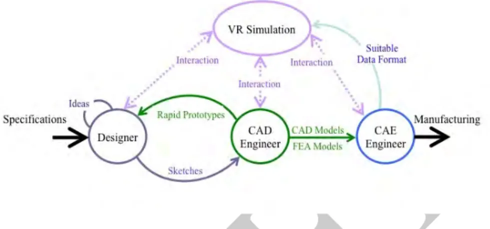
FIGURE 1.1: From specification to manufacturing, introduction of VR in the product design cycle.
deformation simulation in a VR environment enables engineers from different industrial sectors to immerse themselves and to manipulate these digital mock-ups for the purpose of identifying design problems prior to the real prototype phase. The time and costs required for sharing product infor-mation among different sectors would be largely reduced, and therefore the efficiency of the design information exchange in a PLM could be considerably increased.
However, interactive deformation simulation in a VR environment through haptic interfaces is a challenging task because of the trade-off issue between the deformation accuracy and the real time interaction performance. This issue would be troublesome for simulation cases in which complex mechanical deformable parts are taken into account. Namely, the degree of deformation realism tends to require a high meshing resolution, which has a direct impact on the size of the matrices involved in the elasticity system and thus brings a huge computational task difficult to achieve in real time.
Figure 1.1 illustrates a representation of the design cycle with the introduction of VR. As the designer interacts with the computer-aided design (CAD) engineer, who interacts with the CAE engineer, each person uses specialized tools and representations including sketches, rapid proto-types, CAD models, and FEA models. At each stage, VR can be used to both display the 3-D models and allow the designer or engineer to interact with the models in a 3-D environment. Early design choices can play a strategic role in the development of a product relying on virtual proto-types [14, 67]. The use of interactive simulation is mandatory to meet the manipulation requirements allowing the user to manipulate objects and to experience the consequences [11]. In [20, 21], the authors combined the procedures of haptic manipulated shape deformation and shape redesign to-gether in a virtual environment to encourage the rapid investigation of many possible shape design choices. The use of haptic interfaces in VR environments not only enhances users’ capacity to complete virtual tasks, but also provides additional interaction channels during different stages of product design [7, 1]. Therefore, the use of VR and haptic technology contribute to accelerate the decision-making process in the overall product development cycle [62, 19].
This chapter illustrates the action of virtual reality with haptics in the PDP loop for testing de-formable parts by introducing the user in the loop and proposing a two-stage deformation simu-lation method for real time haptic interaction. This two-stage method combines an off-line pre-computation phase and an online deformation interaction phase and is the main concept presented in this chapter.
DRAFT
Motivation 5
• First we present the motivation (Section 1.2) of this work that is underlined by an industrial demand to be able to validate deformation specifications before machining the mold of a designed stamping tool.
• The background section (Section 1.3) emphasizes prior work showing the interest in using virtual reality in the PDP and focuses on model reduction methods showing the specificities of modal analysis methods.
• Then (Section 1.4), we propose a deformation evaluation framework for real time haptic inter-actions by introducing a two-stage method [59]: an off-line phase to pre-compute deformation spaces, similar to a model reduction method [18] but based on modal analysis and, an online phase to enable haptic interactions by a costless response model. A mesh analysis method [60] is then proposed for the pre-computations during the off-line phase. This method allows the off-line phase to calculate different deformation spaces with an accuracy enhancement regard-ing correspondent anticipated scenarios. Thus, the method enables a real time switch among the different pre-computed deformation spaces, so that the online deformation computations focus on degrees of freedom (DOF) where necessary. We introduce a division scheme [61] to ensure real time haptic interaction performance. In the scheme, the deformation computation process is divided into two separate modules, which are then implemented in two separate threads. One module is dedicated to the haptic rendering, which is implemented by extracting a sub-matrix from the pre-computed data matrix, and in this way the haptic rendering process can be quickly refreshed at more than 1,000 Hz. The other module is dedicated to the task of deformation computation and visualization.
• The results (Section 1.5) of the whole process are analyzed on test cases and then proposed on an industrial example of design verification of a stamping mold that represents the industrial process.
• The last section (Section 1.6) proposes a summary of the method, a discussion on the results and, some ideas for future works.
1.2
Motivation
This research has been partially granted by the French government. It concerns the deformation evaluation of mechanical parts within the design process. As an example regarding the stamping process in the automotive industries, the verification of the conformity of a polystyrene part, from which the mold of the stamping tool will be achieved, is of first importance. According to practices in the automotive industry, the polystyrene molds are machined abroad and the evaluation involves physical hand manipulations by an expert sent abroad to verify, on the spot, the functionalities of the physical prototypes. The verifications concern the local stiffness test of local ribs or stiffeners and the global deformation evaluation of the polystyrene part. According to this verification process, where displacements are small for local stiffness testing or can be large rigid body displacements for global deformation evaluation, the strain and stress remain small during this process. In order to reduce the verification costs and to increase the efficiency of data flow in the PLM, the use of VR with force feedback could be a good choice. In a first step, the expert who carries out the evaluation tasks should handle interactively the CAD model of the designed form to evaluate the deformation of the structure under various solicitations as he would have done in the real world. In the following, the CAD model will be the basis for such a deformation analysis and it will be assumed that the
DRAFT
CAD model is a realistic representation of the physical polystyrene form. Our proposed framework should allow real time haptic interactions with an industrial deformable part and propose exploration of the following advantages of applying the VR technology to an industrial PLM:
• Using virtual prototypes to replace the corresponding costly physical models. • Using a VR environment to allow engineers interaction with the virtual prototypes.
• Using haptic interfaces to provide engineers with possibilities to better understand how a deformable mock-up deforms and with more realistic manipulation capabilities.
The deformation computation will have to meet two antagonist requirements. On one hand, a VR application is user-centred, which implies that the size of the models that are handled in the VR ses-sion must be limited so that the real time constraint is well respected. Indeed, the digital model must be carefully prepared before it can be handled in a VR environment. On the other hand, the virtual prototyping (VP) applications are model-centred in order to make the digital model as realistic as possible. Deformation verification processes can be radically different in terms of manipulation. It implies an adaptation of the interaction paradigm as well as a tuning of the simulation parameters to be correctly emulated in a virtual environment. The industrial case defined above implies the definition of a global and a local haptic verification scenarios:
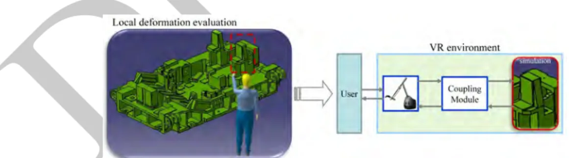
• Local deformation scenario refers to the process of design evaluation of local structures of the part. In Figure 1.2, the deformable mechanical part is represented by the CAD model of a polystyrene stamping mould, while the local structures include ribs or stiffeners. The stiffness validation of these local structures are crucial during the industrial stamping process as they strengthen the bearing capacities of the stamping tool in certain working conditions. In such a scenario, the deformation has to be precisely emulated locally, whereas the coupling between the virtual scene and the haptic device remain relatively simple, involving one manipulation entry (single hand manipulation).
FIGURE 1.2: Local deformation verification scenario: (left) industrial practice of validating such local structures by a single hand of an operator, (right) paradigm of the local deformation
verification scenario in a VR environment.
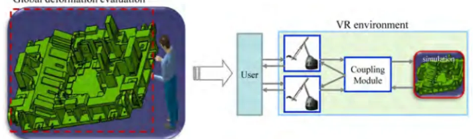
• Global deformation verification scenario refers to the process of design evaluation of the whole deformable mechanical part. In Figure 1.3, the global deformation of the stamping tool is evaluated as the surface accuracy of an industrial product, e.g., a car door, cannot be guaranteed if the geometrical and mechanical properties of the stamping tool are not fully re-spected. In this case, the deformation has to be globally realistic but local deformation details are not needed. However, the manipulation is done by two entries (two hands manipulation) and implies a complex coupling scheme between the virtual scene and two haptic devices.
DRAFT
Background 7
FIGURE 1.3: Global deformation verification scenario: (left) industrial practice of validating the whole structure by two hands of an operator, (right) paradigms of carrying out the global
deformation verification scenario in a VR environment.
1.3
Background
1.3.1
VR in PLM
Virtual prototyping is becoming a commonly adopted design and validation practice in several in-dustrial sectors and, for a long time, companies have been moving from expensive physical proto-types to the direct realization of digital mock-ups. This is clearly true for Boeing [47], Volkswa-gen [14], Chrysler [35], Ford [17], Caterpillar [34], or General Motors [31]–they have been intro-ducing VR technology to reduce the number of physical prototypes by simulations implemented on digital mock-ups in a virtual environment. If we focus on applications that integrate VR, with a special focus on haptics, in PLM, we can propose to classify them into four different themes.
VR for assembly/disassembly applications has been extensively studied because the assembly process constitutes an important part of the cost of a product [6]. Although modern CAD systems can be used in assembly process planning by manually selecting the mating surfaces, axes, and/or edges to assemble the parts, these interfaces do not reflect human interaction with complex parts. Such computer-based systems lack in addressing issues related to ergonomics, for example, to de-tect awkward postures during assembly operations. By applying haptics technology, engineers can touch and feel complex CAD models of parts and interact with them using natural and intuitive human motions [57]. Moreover, collision and contact forces, calculated in real time, can be trans-mitted to the operator using haptic devices and making it possible for him/her to feel the simulated physical contacts that occur during assembly operations. In [49], the authors proposed a physically based modeling for simulating realistic part-to-part and hand-to-part interactions through a dual handed haptic interface. In [53, 54] is proposed a method for interactive assembly operations by applying both kinematic constraints and guiding virtual fixtures. The purpose of this method is to help the user to perform the assembly task and to ensure a good assembly of CAD objects. From an assessment point of view, a quantitative analysis concerning the significance of haptic interactions in performing simulations of manual assemblies was performed by [56, 45].
The project review is a crucial evaluation step of a digital mock-up toward its production. In VR for project review, the stereoscopic rendering on large devices is used mostly to carry out visual tests, e.g., simulations and verifications of the general appearance of the product (color, texture) under different lighting conditions. Automotive industries seem to be the leaders in applying the VR technology for design reviews, which can significantly reduce the costs to produce physical prototypes, saving both money and time in the development process.
Ergonomics studies can be separated into two aspects [42]. The first aspect concerns the user’s point of view and deals with his ability to use a product. The second concerns the workers’ point of view and aims at validating whether it is difficult or not to perform the assembly of two parts.
DRAFT
The goal of ergonomics analysis is the verification of the concept or of the feasibility before the production of a physical model. Ergonomic studies explore whether the contemplated actions for assemblies or the usage of a product are all achieved in a convenient way. This has been studied from a cognitive point of view with a focus on the importance of human input to the design process [28, 10]. The interest in using haptic technology for ergonomic evaluations of assembly tasks has been demonstrated [58, 8] to have the potential to significantly increase both speed and accuracy of human-computer interactions. In the context of improving the ergonomics of workstations in a VR environment and focusing on the user’s ability to perform a given task, a biomechanical model has been proposed [43, 44] as a tool for real time motion analysis of the upper limb of the user.
Focusing on VR for design and simulation analysis, efficient and user-friendly interfaces, par-ticularly involving haptic devices, may improve the use of CAD systems. In [13] is proposed a demonstrator implementing an immersive design solution through voice commands and body ges-tures. This simulator has been improved in [42] by providing haptic solutions for the selection and the modification of digital mock-ups. The research group also proposed a CAD-VR integra-tion paradigm [9] to implicitly edit mechanical parts through multi-modal immersive interacintegra-tions. In [23], the procedures of shape deformation and shape redesign are proposed together in a virtual environment to allow a rapid investigation of many possible shape design choices based on a fast stress analysis and haptics. This method makes it possible to evaluate multiple designs throughout the design process of the product. The deformation simulation is derived from a mesh-free method for performance reasons. Moreover, in [36] is introduced a 3-D object deformation method in an immersive environment dedicated to the development and optimization of industrial parts designed with CAD.
This analysis could have been enlarged to more specific applications as driving simulators and flight simulators. These products also include, most of the time, force feedback that is not restricted to human hands as it is in the case where we used the haptic arm.
1.3.2
Modal analysis as a model reduction method for deformation computation
Deformation modeling methods can be classified into two main categories which are denoted as non-physically based methods and physically based methods, such as those extensively described in the surveys [26, 38]. Assuming the goal of deformation verification, our work will be based on the theory of elasticity [39], part of continuum mechanics, where equations describe the behavior of the continuous media by the description of relationship between four components: displacement, strain, stress, and force. These equations are discretized using the finite element method (FEM) [66] to be applied to 3-D volumetric deformable parts. A classical formulation of this approach is the following system of second-order ordinary differential equations, also known as Euler-Lagrange equations [50]:
M¨u + D(u, ˙u) + R(u) = F (1.1) Here, u (u, v, w) ∈ IR3nis the displacement vector (the unknown), M ∈ IR3n,3n is the mass matrix, D(u, ˙u) are damping forces, R(u) are internal deformation forces, and F ∈ IR3nis the external forces
resulting from user interactions or collision reaction forces. The mass matrix is constant in time and depends only on the object’s mesh and mass density distribution in the undeformed configuration. In general, it is a sparse non-diagonal matrix, however for algorithmic convenience, it is often simplified into a diagonal matrix by accumulating all the row entries onto the diagonal element [65]. Such lumping essentially means that all elements re-assign their volumetrically distributed mass to their vertices: it is as if the model consisted of a point-like mass at every simulation vertex, with zero mass anywhere else inside the elements. Such a construction of course means losing some simulation accuracy. It is true that the accuracy loss is smaller with finer meshes.
DRAFT
Background 9
the real time interaction performance. Moreover, for design verification application, where the body undergoes small deformation even if coupled with large displacements, it is assumed that the linear elasticity theory can be used as strain descriptor and constitutive law. Thus, this linear strain makes the internal force vector linear with respect to the nodal displacement vector. Namely, it simplifies Equation (1.1) to the following linear system:
M¨u + D ˙u + Ku = F (1.2) As the stiffness matrix and the mass matrix remain constant during real time deformation simula-tions, the above-simplified linear system produces an efficient pre-computation process, which is a key to guarantee the real time interaction performance.
As haptic applications require an approximate refresh rate of 1,000 Hz for the haptic rendering, while graphics applications require 30 Hz to 60 Hz [46], a trade-off between the deformation accu-racy and the real time computation speed has to be achieved for simulation of complex mechanical parts. Therefore, the issue of coupling a time-consuming process with a high refresh rate of the haptic loop is a challenge. Basically, two primary categories of solutions can be identified to solve the challenge. Either simplified models based on linearization or reduction are applied, or some pre-computation is performed before the real time interaction occurs.
Multi-resolution methods employ a hierarchical deformation method to adaptively refine the anal-ysis with respect to the deformations of the model. Such methods exploit the fact that a problem can be solved on different scales of resolution. In [55] is proposed a multi-grid deformation solver on a rectangular domain and in [15] is presented an interactive deformation simulator based on an octree representation that was adaptive in both space and time. The multi-resolution method is promising when haptic interfaces are introduced into these deformation simulations, because the multi-resolution representation of a complex deformable object should enable reaching a good trade-off between the real time interaction performance and the deformation fidelity. Some variations of the multi-resolution method were presented concerning haptic contacts or collision handling. A two-level layered deformable model was proposed in [25] where the low-resolution proxy was used to accelerate the computation of collision detections and the contact force renderings, and a high-resolution tetrahedral mesh was applied to achieve highly detailed deformations. A major limitation of this method is that we assume that real time interaction situations are foreseen. As it turns out, however, the real time constraints, e.g., the contact conditions, are normally time-varying and it is not possible to predict them off-line.
Dimensional model reduction methods have been explored extensively in the fields of control theory, electrical circuit simulation, computational electromagnetics, and microelectromechanical systems [2]. They have a long history in the engineering and applied mathematics literature [33]. The common scheme of these methods is to project the original state space on a low-dimensional subspace to reach a much smaller system, which manifests properties similar to those of the original system. Consequently, the dimensionality of the original finite element problem can be considerably reduced, yielding a system consisting of fewer differential equations and fewer unknown variables. These equations can be solved much more efficiently in real time. The key issue of the model reduction method for deformation simulation is the choice of a deformation subspace enabling a proper approximation of the deformation. The generation of such deformation subspace is based on a carefully designed pre-computation. Recently, a statistical approach for deformation basis generation concerning finite element models was presented [32], wherein a full-degree-of-freedom system was first simulated, and then standard principal component analysis (PCA) was applied on the recorded deformation data to obtain a representative deformation basis catching most of the deformation effects. An impulse response deformation model (IRDM) was proposed in [51] by simulating response of the surface mesh nodes of the object. In [4], two methods to generate reduced deformation basis were introduced. The first one is an interactive method based on the user feedback and the second one is based on the linear modal analysis. Complementary information can
DRAFT
be found in [3].
The basic formulation of the model reduction can be stated as: given n initial points associated with the 3n length location vector p = [p1, p2, ..., p3n]T, a reduced deformation model approximates
deformed point locations p0 by a linear superposition of r displacement fields [the columns Uiof U
in Equation (1.3)]. The amplitude of each displacement field is given by the reduced coordinates q by the two equations:
p0= p + u
u = Uq (1.3)
Here U = {U1,U2, ...,Ui, ...,Ur} ∈ IR3n,r is a displacement basis matrix or known as deformation
subspace, specifying a generalized time-independent deformation basis of some r−dimensional (r << 3n) space of IR3n, and q = {q
1, q2, ..., qr}T ∈ IRris the reduced displacement vector, while u
is the spatial displacement vector.
In [30] it is stated that the columns of U could be obtained from any possible carefully designed pre-computations. The selection of a good subspace is a non-trivial problem but can be treated by examining mode frequencies and contributions of the modes to the displacement, when using linear modal analysis. Let us assume that a good subspace is available, and that it is specified explicitly by a deformation basis matrix U.
By inserting u = Uq into Equation (1.2), and pre-multiplying by UT, we obtain the set of the reduced equations of motion which determines the dynamics of the reduced coordinates q:
˜
M¨q + ˜D˙q + ˜Kq = ˜f (1.4) where ˜M¨q, ˜D˙q, and ˜Kq are r−dimensional reduced forces and where:
˜f = UTF (1.5)
The system of ordinary differential equations (ODEs) in Equation (1.4) has a well-defined unique solution, given a specific instance of initial conditions and time-dependent external forces. If r << 3n, the integration of Equation (1.4) is much faster than the integration of the full system represented by Equation (1.2), albeit with some loss in accuracy.
The modal analysis method is an efficient reduction method introduced to computer graphics by [41], but only relatively few significant contributions have been presented since then. James and Pai [29] mapped real time dynamics to graphics hardware: in a pre-computation stage they built a so-called dynamic response texture (DyRT), where mode shapes and other quantities were stored. At run time, the modal coordinates q (called reduced coordinates) were computed from rigid bone transforms or external excitations. Enforcing direct manipulation and collision constraints is straightforward with node positions in an Euclidean space. However, applying these operations in a modal space can be unintuitive. In [27] is provided a solution, in which generalized forces are computed for constrained nodes based on the modal basis. Since the force computation involves evaluating a pseudo-inverse matrix based on the singular value decomposition (SVD), only a few constraints (up to 10 in their examples) can be applied in a real time simulation environment. In the above methods, a linear Cauchy strain model is used to obtain a constant stiffness matrix K, resulting in artifacts for large rotational deformations away from the rest shape. To suppress these artifacts, Choi and Ko [12] identified per-node rotations and extended the basic modal analysis formulation to accommodate these rotations, similar in spirit to the warped stiffness approach [37].
The model reduction method is attractive for real time haptic interactions involving deformable objects, as most of the computational overhead of modeling deformable objects is performed during the pre-computation process. Therefore, the computation power saved during real time interac-tions could be dedicated to represent other complex deformable behaviors, like visco-elasticity and non-linearity. However, the model reduction technique based on pre-computations raises several
DRAFT
Description of the Two-Stage Method 11
difficulties. The first one is to compress the amount of data collected during the pre-computation process, because the reduction of the collected data is essential for a quick access to them in real time interactions [52, 18]. It is true that the number of possible interactions is usually large, since enough pre-computations should be done before real time potential interactions occur. The size of the col-lected data depends heavily on the meshing resolution of a deformable object and the coverage of required deformation behaviors. This leads to the second difficulty: how to design an efficient data collection strategy? Without planning the method of data collections, the pre-computation process will be time-consuming.
By contrast, regarding our goal application and industrial design evaluation requirements, the two-stage method proposed in this article aims at avoiding the aforementioned difficulties raised from the model reduction method. First, during the pre-computation phase, our method computes a linear deformation space based on the modal analysis, similar to the proposition in [27]. Since our pre-computation step is not a random data collection process, we obtain modal deformation vectors and the corresponding modal parameters in a mathematically rigorous way. Moreover our experiments show that this process is not time-consuming and the data storage is small. Second, our predefined global and local scenarios provide an opportunity to plan the pre-computation process efficiently. Regarding these scenarios, we propose a mesh analysis technique, with an accuracy enhancement, which is dedicated to these anticipated scenarios. Third, considering the different refresh rates of the haptic rendering and the visual rendering, we propose to divide the deformation computation process into two separate modules: a haptic rendering module and a visualization module, which are actually implemented on different threads. Our haptic rendering process can be quickly refreshed at more than 1,000 Hz by extracting a sub-matrix from the pre-computed data matrix. However, the update rate of the visualization process is lower and it heavily depends on the meshing densities.
1.4
Description of the Two-Stage Method
As discussed in the previous section, the physically based real time haptic interaction with de-formable objects formulated by the FEM and the elasticity theory could lead to a huge mathemat-ical system. Thus the process of the solution is computationally expensive and hinders the real time interactivity. For this reason, we propose a two-stage deformation modeling method for haptic interaction by combining an off-line pre-computation phase and an online deformation interaction phase. Thanks to this method, most of the heavy computational task is carried out off-line and consequently, we obtain a costless deformation response model, which ensures a stable real time interaction experience. Particularly, the off-line pre-computation aims at handling those deforma-tion modeling components by proposing a feasible flow starting from an original digital model to a physical model represented by deformation spaces and the corresponding constraints. Then the on-line deformation interaction phase manages an appropriate response of the deformable model with respect to the pre-computed deformation spaces and the interaction requirements.
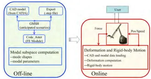
Figure 1.4 shows the overall structure of our two-stage deformation simulation method [59], which consists of two main phases: an off-line pre-computation phase, and a real time interaction phase. The detailed computation process of both phases is presented in the subsequent sections.
1.4.1
Off-line pre-computation phase
The off-line pre-computation phase of our method is a linear modal analysis of the considered deformable object.
DRAFT
FIGURE 1.4: Deformation simulations based on two-stage method: an off-line pre-computation module (left), and a real time interaction module (right).
As only small deformations are concerned for the design evaluation of industrial deformable parts, we will focus on the linearized version of the equation of motion, which admits a high degree of pre-computation, and thus leads to a quick real time deformation response model suitable for haptic interactions. In our method, from the mass, damping, and stiffness matrices M, D, and K obtained by FEA, Equation (1.2) is decoupled into 3n linearly independent ODEs leading to Equation (1.4) by solving the generalized eigenvalue problem:
MΦΛ = KΦ (1.6)
such that ΦTMΦ = I and ΦTKΦ = Λ are diagonal matrices. Λ contains the eigenvalues, and the columns of Φ = {ϕ1, ϕ2, ..., ϕi, ..., ϕN} contain the eigenvectors of M−1K. Φ is usually termed
the modal matrix, in which ith column ϕi represents the ith mode (e.g., one vector of the basis of
3n−dimensional space), and the ithentry of Λ is proportional to the square of the eigenfrequency. For volumetric deformation simulations, the first six of the vibrational modes, associated with a null eigenfrequency, account for rigid body motion (object position and orientation). In many applications, it is not necessary to choose all of the vibrational modes to describe the behavior of a deformable object. Higher order modes generally exhibit smaller displacement amplitudes, their resonant frequencies can be higher than simulation frame rates and these frequencies are higher than the frequencies applied by the user’s solicitation. In order to reduce the number of DOFs in the ODEs system to enable a faster simulation, one can disregard higher frequency modes while choosing the number of modes with respect to the simulation requirements [40]. In our examples, we have observed that a number of 30 modes, as proposed in [40], ensures results with almost no error with respect to the simulation that includes all the possible modes (e.g., 3n). Nevertheless, in situations where accuracy is important, additional motion details can be added systematically by including higher frequency modes in the analysis. Thus, a modal representation is ideal for controlling level of detail (LOD) in deformable object simulations leading easily to the condition r<< 3n.
Substituting U by Φ in Equation (1.4), the coefficients of general terms of forces in a r-dimension space can be rewritten as follows:
˜
MΦ= ΦTMΦ = diag(mi) (1.7)
˜
DRAFT
Description of the Two-Stage Method 13
˜fΦ= ΦTF = { f1, f2, ..., fi, ..., fr}T (1.9)
Here ˜MΦ and ˜KΦ are diagonal matrices, and ˜fΦis the modal force vector. However, for general
damping, ˜DΦ is dense because there is no reason why it should be diagonalized in the same basis
as M, and K (e.g., Φ). If we assume proportional (Rayleigh) damping D = αM + β K, then ˜DΦ=
α I + β Λ is also diagonal [see Equation (1.10)]. Here, α and β are material-dependent positive scalars [50]. We can now decouple Equation (1.4) and express it by 3n independent scalar 2nd ODEs as in Equation (1.11).
di= αmi+ β ki (1.10)
miq¨i+ diq˙i+ kiqi= fi, i= 1, 2, ..., r (1.11)
Here the scalar values mi, di, and kiare the modal mass, the modal stiffness, and the modal damping
of the ithlinear mode, respectively. The force f = { f
1, f2, ..., fr}T is the modal force vector, which
results from a projection of F on a modal subspace Φ. By defining the un-damped natural frequency of vibration ωi(in radians),
ωi=
r ki
mi
(1.12)
and therefore the ithdiagonal element of Λ termed λican be written as follows.
λi=
ki
mi
= ωi2 (1.13)
By inserting Equation (1.10) into Equation (1.11) and substituting the corresponding terms in Equations (1.12) and (1.13), we obtain the classical form of the equations’ set:
¨
qi+ (α + β λi) ˙qi+ λiqi=
fi
mi
(1.14)
Once the reduced displacement vector q is computed, the displacement vector u can be received by back-substitutions in Equation (1.3). As detailed in [27], each of these equations in Equa-tion (1.14) has an analytical soluEqua-tion of the following form:
qi= c1er1t+ c2er2t (1.15)
where the constants c1 and c2depend on the initial conditions, and the root of the characteristic
equation r2+ (α + β λi)r + λi= 0 are
r1,2=
−(α + β λi) ±p(α + β λi)2− 4λi
2 (1.16)
The solution depends on the sign of R = (α + β λi)2− 4λi: R > 0, R = 0, and R < 0 produces
the over-damped (r1, r2real and different), critically damped (r1, r2real but repeated), and
under-damped case (r1, r2are complex conjugates), respectively, and therefore qiin Equation (1.14) will
be a real value.
To conclude, we can examine the eigenvalues, discard high frequency mode shapes, and thereby only use dominant modes with the decoupling of original ODEs based on the modal analysis. This process can significantly reduce the computational cost, and thus contributes to the haptic interaction with deformation simulations. In this work, the modal parameters introduced in the above equations are pre-computed during an off-line phase. And thus, during the real time interaction phase, the motion components qi of an individual mode are computed independently and combined by the
DRAFT
principle of linear superposition. The choice of deformation modes depends on the simulation features. For example, low frequency modes are chosen if a global deformation is considered, while high frequency modes are chosen for local deformations (testing of ribs stiffness).
The choice of the tools, as presented in Figure 1.4, is independent of the method. Our pre-computation process starts on the geometrical modeling in a CAD software (e.g., CATIATM). Con-sidering the format compatibility between the CAD software and the meshing tool, a “step” file is exported. We choose GMSH to mesh our digital models as it integrates the NetGen and TetGen modules. And moreover it is also equipped with pre-processing and post-processing facilities and GMSH accepts a file format compatible with “step” format. During this step, the meshing results are stored in two different formats: “.msh” and “.txt.” The “.msh” file serves as input of Code-Aster1 for the deformation computation process, while the “.txt” file stores the topology of the mesh model. An advantage of choosing Code-Aster as a pre-computation tool is that it provides free accessibility to the finite element module, and it allows user-defined constraints on the deformable object for dif-ferent computational purposes. Although this FEA software is provided under open-source license, it was developed and is used by a major company for its own studies. Every update on Code-Aster is tested on test cases and compared either to analytic solutions or to other reference solutions ob-tained by commercial software. Moreover, before deciding to implement it, we tested the results with respect to the one obtained by commercial FEA software embedded in CATIA.TM
1.4.2
Online interaction phase
This phase aims mainly at computing the real time responses of the deformable object considering two aspects: the realization of the haptic rendering loop and the deformation computation of the whole object. The key blocks of our real time phase are shown on the right side of Figure 1.4, starting from the application of user’s forces by the haptic device, the reduced modal forces are computed, and the reduced displacement and physical displacement are computed by solving Equa-tion (1.11). Finally the posiEqua-tion and speed feedback are delivered to the haptic device, used in admittance mode, which provides the user with force and torque feedback. As a numerical scheme, we choose implicit Newmark integration scheme, as it is a second-order accuracy method and as it allows relatively large time steps. These two advantages guarantee better accuracy and better interactive performance (more details can be found in [5]).
The size of a deformation space Φ grows quickly with the increase in the dimension r or the increase in the complexity of deformable objects. And thus the process of u(t) = Φrqr(t) becomes
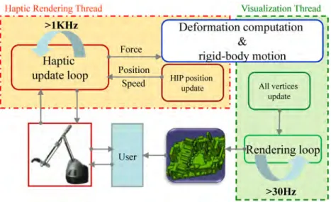
the main time-consuming task for real time haptic interactions with modal deformations. In order to obtain a stable and realistic interaction experience, we propose an online deformation division scheme to meet, on one hand, the high refresh rate of the haptic rendering loop, and on the other hand, the update rate of the graphical rendering loop. Commonly the haptic loop is decoupled from the simulation and rendering loops, enabling maintenance of a high refresh rate for haptics while interacting with a slow deformable body simulation. We propose an online deformation division scheme [59], as shown in Figure 1.5. In our division scheme, the deformation computation process is divided into two separate modules, which are implemented on two different threads. A haptic rendering thread is dedicated to update the haptic interaction point’s (HIP) position and speed, while a visualization thread is dedicated to update the new positions of all vertices.
As the method is based on modal analysis in FEM, the vertex is the natural entity for picking. In the haptic rendering thread (Figure 1.5, left), when the HIP selects an active vertex, the index (e.g., ithvertex) of this active vertex is recorded, and the corresponding modal subspace is chosen.
To prevent the user from picking an empty space, the picked vertex is the closest one from the HIP. Doing that, one must assume that the model is fine enough. The forces applied at the end effector
DRAFT
Description of the Two-Stage Method 15
FIGURE 1.5: Online division scheme consists of two separate modules implemented on different threads: (left) HIP position update module to meet high refresh rate of haptic rendering,
and (right) all vertices update module to meet the lower refresh rate of graphical rendering.
are recorded in F to compute the corresponding modal force f with Equation (1.9). The response of each mode in terms of displacement resulting from Equation (1.11) are assembled in q and the displacement and the position of the active vertex are quickly computed by Equation (1.17).
ui= Φiq, pi= pio+ ui (1.17) Here, pi
oand piare the initial and deformed position of the active vertex, respectively. The position
piis set to update the haptic rendering loop at a high refresh rate (> 1, 000 Hz), according to our
experiments (see Section 1.5). The implementation of the force feedback part is based on a coupling in impedance mode by simply using the dedicated application programming interface (API) of the used device.
The visualization thread (Figure 1.5, right) computes the deformation of the entire object by applying Equation (1.3) and using the history of reduced displacement vector q, which is passed from the haptic rendering thread through a shared memory. Then, the deformations are rendered with a lower refresh rate and the value depends heavily on the meshing densities. We did not focus on the performance for this thread. By using a good graphic library (e.g., Openscenegraph) or by using dedicated hardware (GPU), the refresh rate could be easily optimized to reach the state-of-the art in graphic rendering.
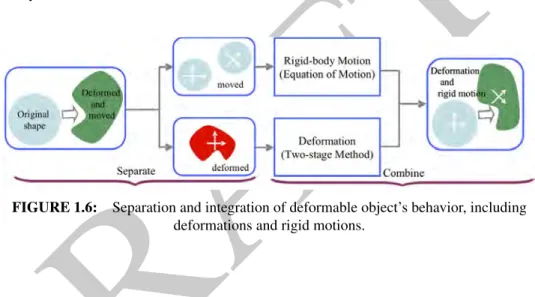
We mentioned that parts, although they are submitted to small deformation, may encounter large displacements due to a global rigid-body motion of a deformable object. Figure 1.6 illustrates the key idea of separating and integrating the rigid-body motion and the deformation. In the off-line pre-computing phase, the total behavior computed by FEM simulation is separated into two com-plementary components. The component of rigid-body motion, associated with the null frequency modes, is naturally discarded and the deformation component is represented by the modal deforma-tion space. During the online deformadeforma-tion interacdeforma-tion phase, the rigid-body modeforma-tion is reproduced using the classical equations of motion [Equation (1.18)], while the deformation is computed based on the two-stage deformation modeling method. The total behavior is obtained by combining the components of motion and deformation.
DRAFT
Mdv
dt =
∑
fext= F w× (Iw) + Idwdt =
∑
τext (1.18) where, M is the total mass of the elastic object, I is inertia tensor, v and w are velocity and angular velocity of a rigid object, respectively, and F and τext are external force and external torque that areapplied by users.
FIGURE 1.6: Separation and integration of deformable object’s behavior, including deformations and rigid motions.
1.4.3
Discretization Improvement
During off-line pre-computations, it is not necessary to mesh the object by applying a unified mesh-ing resolution on a complex deformable object for real time haptic interactions, as the deformation is concentrated in a local region when an operator interacts with local ribs or stiffeners. We propose a mesh analysis method that aims at enhancing locally the deformation accuracy considering the object as separate anticipated volumes of interest (VOI).
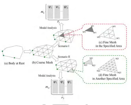
Figure 1.7 illustrates the mesh analysis method in a 2-D case for the purpose of simplicity as the extension to 3-D part is straightforward. A coarse mesh is applied to an entire deformable object. We suppose that there are several specified areas in the coarse mesh, which result from predefined scenarios (e.g., scenario I and II shown in Figure 1.7). Each of these areas is meshed with an increased mesh density while the other areas keep the original density mesh. The different modal deformation spaces (e.g., Φ3n1,r1, Φ3n2,r2, ... Φ3nk,rk) are stored separately with respect to different
meshing qualities.
This method can be seen as a pre-computed adaptive meshing method inspired from [16]. The standard adaptive meshing method relies on online re-meshing procedures that are CPU time-consuming and thus not always suitable for real time interactions. In our method, most of the overhead of mesh preparations is incurred during an off-line phase by decoupling a deformable ob-ject into separate VOIs, so that the regions in the anticipated scenarios can be computed accurately in real time, while fulfilling the goal of reducing the online computational costs. The essence of our mesh analysis method is to pre-compute several mesh representation models of a single CAD object, and during real time interactions, to choose the appropriate representation of the object ac-cording to the touch position of the mesh node. This method has been successfully used when the identification of VOI is predictable (e.g., case of well-identified ribs or stiffeners).
DRAFT
Results 17
FIGURE 1.7: 2-D demonstration of the mesh analysis technique based on anticipated scenarios (e.g., scenario I and II) – a coarse mesh is applied to an entire body. Several specified areas in
different scenarios are meshed using different meshing densities, (c) and (d).
1.5
Results
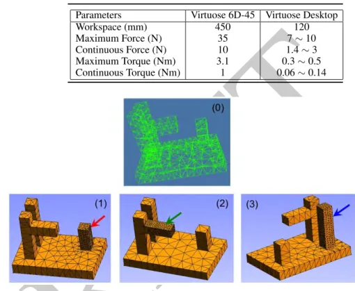
These first results are based on the use of one simple CAD model, consisting in a plate and four beams and used as a test case with four different representative meshes. It aims at illustrating our off-line mesh analysis method and the online switch scheme among different deformation spaces corresponding with these sub-models. In Figure 1.8, the bottom three models illustrate three VOIs with denser meshing resolutions of the same part depending on which beam is tested by the user. During real time interactions, the corresponding modal space is switched based on the control of the HIP by the user. The complexities of those models are listed in Table 1.2 and the time required for off-line pre-computations and the data storages are listed at the bottom of the table. The Young’s modulus is E = 2, 200 N/m2, the Poisson’s ratio is ν = 0.38, and the density is ρ = 1, 200 kg/m3 corresponding to the constitutive parameter of polystyrene and are also used for the industrial case. Of course, these values can be adapted to all kinds of linear elastic isotropic homogeneous materials. The computer used was an Intel R CoreTM2 Duo CPU 2.6 GHz, RAM 3.00 GB on Windows
XP operating system and we implemented two different haptic devices with the same API (Virtuose 6D-45 and Virtuose Desktop from HAPTION company2) with the characteristics listed in Table 1.1. In Table 1.2, we present the data of the three sub-models [e.g., model (1), (2), and (3)] of model (0). The time needed for our pre-computation is not time-consuming and the data storage is small compared with [52]. This is an advantage of the off-line phase based on the modal deformation spaces pre-computations, which makes it easier to store these modal data and to reproduce rapidly the deformations in the real time phase.
In comparison with corresponding results from a non-reduced deformation space (e.g., whole
DRAFT
TABLE 1.1:
Parameter configuration of the two haptic devices.Parameters Virtuose 6D-45 Virtuose Desktop Workspace (mm) 450 120 Maximum Force (N) 35 7 ∼ 10 Continuous Force (N) 10 1.4 ∼ 3 Maximum Torque (Nm) 3.1 0.3 ∼ 0.5 Continuous Torque (Nm) 1 0.06 ∼ 0.14
FIGURE 1.8: Experimental mesh models : (top) model (0) a CAD mesh model with three local beams, and (bottom) three refined meshes (1), (2), and (3) depending on the VOI.
TABLE 1.2:
Complexity of our experimental models. (0) (1) (2) (3) nodes (n) 291 630 877 775 tetrahedrons 795 2,275 3,337 2,962 off-line (sec) 8.4 10.0 10.5 9.7 data size (MB) 0.7 0.8 1.0 0.9FEA of the model simulated off-line), a number of 20 to 30 retained modes allows obtaining less than 2% of relative error on displacements and to correctly represent twisting of the beams. On these models, according to our interaction experience, removing the higher frequencies modes does not change visually the resulting simulation, although we did not notice any perceptive change from a haptic point of view. However, the choice of the relevant deformation modes could be adaptive and could benefit from the work presented in [64], where the authors extensively presented the high-quality modal sound synthesis by investigating mode-adaptive simulations and by defining adaptive criteria for increasing or decreasing the number of modes.
One main benefit of a modal deformable model is that the simulation can be performed in real time, as each of the decoupled equations can be solved efficiently.
DRAFT
Results 19
time during a simulation. The separation of haptic and visualization threads of our method leads to a haptic thread update rate of 3 KHz when the user interacts haptically with the simulation and of 10 KHz when the user only manipulates the HIP. These rates induce smooth interactions with our experimental models and is almost independent of the model’s complexity. This is a significant feature of the proposed division scheme, as we extract a sub-matrix, which is much smaller in size, to compute the position and speed of the active vertex. The update rate of the visualization thread for this simple model is very stable at 60 Hz and is sufficient for interaction applications. This update value of the visualization thread depends heavily on the complexity of the model and of its mesh density.
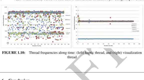
The initial industrial CAD model has been tested following our method according to the local deformation scenario presented in Figure 1.2 and to the global deformation scenario presented in Figure 1.3. The local deformation scenario represents the validation of stiffness of local structures while the global deformation scenario represents the evaluation of the deformation of the whole part. In this section, this model is meshed by 21,499 mesh vertices and 88,198 tetrahedrons and the data storage of the pre-computation data is 137 Mbytes. The constitutive laws are the same as presented above. Figure 1.9 shows the real time interaction scenarios of this industrial model. The left part of the picture shows a global deformation scenario based on the lift of the part by holding it in a corner, while the right part of the picture presents a local deformation scenario where the user applies locally a force on a rib through the haptic interface. As stated above, for this model, the update rate of the haptic thread is not affected by the complexity of the model. Due to the complexity of the CAD model, the update rate of the visualization thread decreases to 10 Hz, which poses problems for interactive applications.
The haptics update rate denoted a high standard deviation (SD), relying hardly on the solicitation applied to the model by the user. On the other hand, performance did not decrease drastically when manipulating the industrial CAD model. It shows that the modal analysis is robust against the complexity of the model. Contrary, the graphics update rate depended mainly on the model complexity, whereas the solicitation did not significantly change the refresh rate. The most complex model (industrial CAD model) drastically decreased the graphic’s performance. This issue does not depend on the method proposed in this chapter and could be addressed by working on more efficient graphics rendering environments as, for example, by exploring the use of GPU implementation [63].
FIGURE 1.9: real time haptic interaction scenario of an industrial CAD model: (left) global deformation, and (right) local deformation
DRAFT
FIGURE 1.10: Thread frequencies along time: (left) haptic thread, and (right) visualization thread
1.6
Conclusion
The goal of this work was to investigate the real time deformation simulation through haptic inter-faces for the purpose of the design evaluation of deformable mechanical parts in the process of an industrial PLM. We have first presented a review of related work on the integration of the VR tech-nology and the industrial PLM. Then, we presented the theoretical background of the deformation modeling methods and the mathematical formulation of the finite element method. We identified the key challenges of haptic interactions with deformable mechanical parts in terms of the trade-off issue between the deformation accuracy and the real time interaction performance. Then, we pre-sented a survey of relevant work on real time deformation modeling methods, which were dedicated to handle the trade-off issue. We stressed that the model reduction method was more attractive for the real time haptic interaction with deformable mechanical parts, which were formulated by the FEM. Based on this background, we focused on the development of a real time deformation simulation framework for haptic interactions.
In this chapter, we proposed a two-stage method for the small deformation modeling and com-bined it with the large rigid-body motion for the purpose of design evaluation of an industrial de-formable part, aiming at dealing with the trade-off between the deformation accuracy and the inter-action performance within an industrial context. In our method, the off-line pre-computation phase provides a costless deformation response model for the real time interactions. Moreover, our mesh analysis method based on anticipated scenarios allows the real time deformation to be computed with an accuracy enhancement on degrees of freedom where they are necessary. And our online division scheme ensures the haptic thread to be refreshed at more than 1,000 Hz, which provides a smooth interaction experience. Experimental results showed that our two-stage method could ef-ficiently handle the trade-off issue by guaranteeing the deformation accuracy and providing stable real time haptic interaction. We did not implement any method to prevent the user to pull a vertex too far. We could imagine using a drastic change in force feedback magnitude or a release in force feedback when the user drives the model outside its validity (linear) zone.
There are several potential industrial applications that could benefit from the deformation mod-eling and the real time interaction method proposed in this paper. One example is the real time deformation simulation for the integration of interactive analysis and redesign in a VR environ-ment [23]. Another example is to introduce volumetric deformations into the procedure of virtual assemblies or maintenance operations guided by haptic interfaces.
However, the future work of improving or extending our method will be mainly focused on the following three aspects. First, concerning the low interactive rate of complex industrial CAD mod-els, one possible solution is to simplify the geometry before the off-line pre-computations, since
DRAFT
References 21
the geometry simplification is a common pre-process of finite element analysis [24]. Another pos-sible solution is to extend our mesh analysis method to a multi-fold representation of deformable objects [48].
Second, we limit the interaction possibilities to a selection of possible manipulations, which means that the pre-computation process must be carried out again for a new interaction scenario, as our two-stage method depends heavily on the prescribed boundary conditions. It is an important future work to extend the capacity of our method to allow arbitrary interactions by considering the time-variant boundary conditions [27] or by generating the “pre-computation” data during the interaction by distributed computational resources [22].
Third, the visualization of the deformation is not sufficient for mechanical industries, and thus some other results are equally required, e.g., stresses and strains fields [20, 21]. It would also be interesting to explore the change in haptic force depending on the stress or strain by performing a user study. This could be important for interactive deformation analysis applications, because the conversion from the stress state to a value for a haptic device could be an enhancement to aid designers to better understand how a part deforms in the early design phase.
References
[1] Faieza A. Aziz and Maryam Mousavi. A review of haptic feedback in virtual reality for manufacturing industry. Journal of Mechanical Engineering, 40(1):68–71, 2009.
[2] Zhaojun Bai and Ren-Cang Li. Structure-preserving model reduction using a Krylov subspace projection formulation. Comm. Math. Sci., 3(2):179–199, 2005.
[3] Jernej Barbiˇc. Real-time Reduced Large-Deformation Models and Distributed Contact for Computer Graphics and Haptics. PhD thesis, Computer Science Department School of Com-puter Science Carnegie Mellon University, 2007.
[4] Jernej Barbiˇc and Doug L. James. Real-time subspace integration for St. Venant-Kirchhoff deformable models. ACM Transactions on Graphics (SIGGRAPH 2005), 24(3):982–990, 2005.
[5] C. Basdogan. Real-time simulation of dynamically deformable finite element models using modal analysis and spectral Lanczos decomposition methods. In Proceedings of the Medicine Meets Virtual Reality, pages 46–52, 2001.
[6] G. Boothroyd and P. Dewhurst. Product Design for Assembly. McGraw-Hill, New York, 1989.
[7] Monica Bordegoni and Umberto Cugini. Haptic modeling in the conceptual phases of product design. Virtual Reality, 9(2-3):191–202, 2006.
[8] Monica Bordegoni, Umberto Cugini, Paolo Belluco, and Marcello Aliverti. Evaluation of a haptic-based interaction system for virtual manual assembly. In Proceedings of the 3rd International Conference on Virtual and Mixed Reality, pages 303–312, Berlin, Heidelberg, 2009. Springer-Verlag.
[9] P. Bourdot, T. Convard, F. Picon, M. Ammi, D. Touraine, and J.M. Vzien. VR-CAD integra-tion: Multimodal immersive interaction and advanced haptic paradigms for implicit edition of CAD models. Computer-Aided Design, 42(5):445–461, 2010.
DRAFT
[10] John E. Brough, Maxim Schwartz, Satyandra K. Gupta, Davinder K. Anand, Robert Kavetsky, and Ralph Pettersen. Towards the development of a virtual environment-based training system for mechanical assembly operations. Virtual Reality, 11:189–206, 2007.
[11] Grigore C. Burdea and Philippe Coiffet. Virtual Reality Technology. John Wiley & Sons, Inc., New York, NY, USA, 2 edition, 2003.
[12] Min Gyu Choi and Hyeong-Seok Ko. Modal warping: Real-time simulation of large rotational deformation and manipulation. IEEE Transactions on Visualization and Computer Graphics, 11:91–101, 2005.
[13] T. Convard. Conception Assist´ee par Ordinateur en Environnement Immersif. PhD thesis, Universit´e Paris Sud XI, 2005.
[14] F. Dai, W. Felger, T. Fr¨uhauf, M. G¨obel, D. Reiners, and Gabriel Zachmann. Virtual proto-typing examples for automotive industries. In Virtual Reality World, 1996.
[15] Gilles Debunne, Mathieu Desbrun, Alan H. Barr, and Marie-Paule Cani. Interactive multires-olution animation of deformable models. In Eurographics Workshop on Computer Animation and Simulation (EGCAS), 1999.
[16] Gilles Debunne, Mathieu Desbrun, Marie-Paule Cani, and Alan H. Barr. Dynamic real-time deformations using space & time adaptive sampling. In Proceedings of the 28th annual con-ference on Computer graphics and interactive techniques, pages 31–36. ACM, 2001. [17] D. Deitz. Real engineering in a virtual world. Mechanical engineering, 117:78–85, 1995. [18] JL. Dulong, F. Druesne, and P. Villon. A model reduction approach for real time part
defor-mation with non-linear mechanical behaviour. International Journal on Interactive Design and Manufacturing, 1:229–238, 2007.
[19] John Eddy and Kemper E. Lewis. Visualization of multidimensional design and optimization data using cloud visualization. In Proceeding of International Design Engineering Technical Conferences and Computers and Information in Engineering Conference (IDETC/CIE2002), pages 30–43, 2002.
[20] Daniela Faas, Andrew Fischer, and Judy M. Vance. Interactive mesh-free stress analysis for mechanical design assembly with haptics. In ASME 2007 International Design Engineering Technical Conferences, DETC07-34660, Las Vegas, 2007.
[21] Daniela Faas and Judy M. Vance. Interactive deformation through mesh-free stress analysis in virtual reality. In ASME 2008 International Design Engineering Technical Conferences and Computers and Information in Engineering Conference, volume 3, NYC, 2008.
[22] Jiˇr´ı Filipoviˇc, Igor Peterl´ık, and Ludˇek Matyska. On-line precomputation algorithm for real-time haptic interaction with non-linear deformable bodies. In Proceedings of the World Hap-tics 2009 - Third Joint EuroHapHap-tics conference and Symposium on Haptic Interfaces for Vir-tual Environment and Teleoperator Systems, pages 24–29, 2009.
[23] Andrew Fischer, Judy M. Vance, and Dao M. Vo. Haptic feedback to guide interactive product design. In World Conference on Innovative Virtual Reality (WINVR09), 2009.
[24] G. Foucault, P-M. Marin, and J-C. L´eon. Mechanical criteria for the preparation of finite element models. In 13th International Meshing Roundtable, pages 413–426, 2004.
[25] Nico Galoppo, Serhat Tekin, MiguelA. Otaduy, Markus Gross, and Ming C. Lin. Interactive haptic rendering of high-resolution deformable objects. In Randall Shumaker, editor, Virtual Reality, volume 4563 of Lecture Notes in Computer Science, pages 215–223. Springer Berlin Heidelberg, 2007.
DRAFT
References 23
[26] Sarah F. F. Gibson and Brian Mirtich. A survey of deformable models in computer graphics. In Computer Graphics, 1997.
[27] Kris K. Hauser, Chen Shen, and James F. O’Brien. Interactive deformation using modal analysis with constraints. In Graphics Interface, pages 274–256, 2003.
[28] P. O’B Holt, J. M. Ritchie, P. N. Day, J. E. L. Simmons, G. Robinson, G. T. Russell, and F. M. Ng. Immersive virtual reality in cable and pipe routing: design metaphors and cognitive ergonomics. Journal of Computing and Information Science in Engineering, 4(3):161–170, 2004.
[29] Doug James and Dinesh Pai. DyRT: Dynamic response textures for real time deformation simulation with graphics hardware. ACM Transactions on Graphics (SIGGRAPH 2002), 21(3):582–585, 2002.
[30] Doug L. James and Dinesh K. Pai. BD-Tree: output-sensitive collision detection for reduced deformable models. ACM Transactions on Graphics (SIGGRAPH 2004), 23(3), 2004.
[31] G. Kobe. Virtual interiors. Automotive Industries, 175(5):52–54, 1995.
[32] P. Krysl, S. Lall, and J. E. Marsden. Dimensional model reduction in non-linear finite el-ement dynamics of solids and structures. International Journal For Numerical Methods In Engineering, 51(51):479–504, 2001.
[33] J. L. Lumley. The structure of inhomogeneous turbulent flows. Atmospheric turbulence and wave propagation, pages 166–178, 1967.
[34] D. P. Mahoney. Driving VR. Computer Graphics World, 18(5):22–23, 1995.
[35] D. P. Mahoney. VR drives chrysler’s new car. Computer Graphics World, 20(7):61–62, 1997.
[36] Vincent Meyrueis, Alexis Paljic, and Philippe Fuchs. D3: an immersive aided design defor-mation method. In Proceedings of the 16th ACM Symposium on Virtual Reality Software and Technology, pages 179–182. ACM, 2009.
[37] Matthias M¨uller, Julie Dorsey, Leonard McMillan, Robert Jagnow, and Barbara Cutler. Stable real-time deformations. In Proceedings of the 2002 ACM SIGGRAPH/Eurographics sympo-sium on Computer animation, pages 49–54. ACM, 2002.
[38] Andrew Nealen, Matthias Mller, Richard Keiser, Eddy Boxerman, and Mark Carlson. Physi-cally based deformable models in computer graphics. Computer Graphics Forum, 25(4):809– 836, 2006.
[39] J.T. Oden. Finite Elements of Non-linear Continua. Dover Publications Inc, 1972.
[40] A. Pentland and S. Sclaroff. Closed-form solutions for physically based shape modeling and recognition. IEEE Transactions on Pattern Analysis and Machine Intelligence, 13(7):715– 729, 1991.
[41] A. Pentland and J. Williams. Good vibrations: Modal dynamics for graphics and animation. Compter Graphics, 23(3):207–214, 1989.
[42] Flavian Picon. Interaction Haptique pour la Conception de Formes en CAO Immersive. PhD thesis, Universit´e Paris XI, 2010.
[43] Charles Pontonnier and Georges Dumont. Inverse dynamics method using optimisation tech-niques for the estimation of muscle forces involved in the elbow motion. International Journal on Interactive Design and Manufacturing (IJIDeM), 3:227–236, 2009.
DRAFT
[44] Charles Pontonnier and Georges Dumont. From motion capture to muscle forces in the human elbow aimed at improving the ergonomics of workstations. Virtual and Physical Prototyping, 5(3):113–122, 2010.
[45] Charles Pontonnier, Georges Dumont, Afshin Samani, Pascal Madeleine, and Marwan Badawi. Designing and evaluating a workstation in real and virtual environment: From digi-tal mock-up to realization. In Cognitive Infocommunications (CogInfoCom), 2012 IEEE 3rd International Conference on, pages 249–254, 2012.
[46] E. Saddik. The potential of haptics technologies. IEEE Instrumentation and measurement magazine, 10(1):10–17, 2007.
[47] B. Schmitz. Great expectations: The future of virtual design. Computer-Aided Engineering, 14(10):68–72, 1995.
[48] M. Seiler, J. Spillmann, and M. Harders. A threefold representation for the adaptive simulation of embedded deformable objects in contact. Journal of WSCG, 18(1-3):89–96, 2010.
[49] Abhishek Seth, Hai-Jun Su, and Judy M. Vance. Sharp: A system for haptic assembly and realistic prototyping. In ASME 2006 International Design Engineering Technical Conferences and Computers and Information in Engineering Conference, September 2006.
[50] Ahmed A. Shabana. Theory of Vibration, Volume II: Discrete and Continuous Systems. Springer-Verlag, New York, NY, 1990.
[51] Kazuyoshi Tagawa, Koichi Hirota, and Michitaka Hirose. Impulse response deformation model: an approach to haptic interaction with dynamically deformable object. In Proceedings of 14th Symposium on Haptic Interfaces for Virtual Environment and Teleoperator Systems. IEEE, 2006.
[52] Kazuyoshi Tagawa, Koichi Hirota, and Michitaka Hirose. A data compression method for impulse response deformation model. In Symposium on Haptic Interfaces for Virtual Envi-ronment and Teleoperator Systems, pages 428–433, 2009.
[53] L. Tching, G. Dumont, and J. Perret. Haptic assembly of CAD models using virtual constraint guidance. In Proceedings of ASME 2010 World Conference on Innovative Virtual Reality (WINVR 2010), 2010.
[54] L. Tching, G. Dumont, and J. Perret. Interactive simulation of CAD models assemblies using virtual constraint guidance. International Journal on Interactive Design and Manufacturing (IJIDeM), 4(2):95–102, 2010.
[55] Demetri Terzopoulos and Kurt Fleischer. Modeling inelastic deformation: Viscoelasticity, plasticity, fracture. In Proceedings of SIGGRAPH’88, 1988.
[56] Dao M. Vo, Judy M. Vance, and Mervyn G. Marasinghe. Assessment of haptics-based in-teraction for assembly tasks in virtual reality. World Haptics Conference, pages 494–499, 2009.
[57] Sergei Volkov and Judy M. Vance. Effectiveness of haptic sensation for the evaluation of virtual prototypes. ASME Journal of Computing and Information Sciences in Engineering, 1(2):123–128, 2001.
[58] Steven Wall and William Harwin. Quantification of the effects of haptic feedback during a motor skills task in a simulated environment. In Proceedings of Phantom User Research Symposium’00, 2000.
DRAFT
References 25
[59] Zhaoguang Wang and Georges Dumont. Real Time Interaction with Deformable Industrial CAD Model through Haptic Interface in VR. In Proceedings of IDMME-Virtual Concept 2010, pages 20–23, Bordeaux, France, 2010.
[60] Zhaoguang Wang and Georges Dumont. Haptic manipulation of deformable CAD parts with a two-stage method. International Journal on Interactive Design and Manufacturing (IJIDeM), 5(4):255–270, 2011.
[61] Zhaoguang Wang and Georges Dumont. Interactive Design Validation of Deformable Parts Through Haptic Interface. In Proceedings of the ASME World Conference on Innovative Virtual Reality (WINVR2011), pages 133–143, Milan, Italy, June 27-29 2011. ASME. [62] Xianglong Yang, Yuncheng Feng, Tao Li, and Fei Wang. Solving sequential decision-making
problems under virtual reality simulation system. Winter Simulation Conference, 1:905–912, 2001.
[63] Che Yinghui, Wang Jing, and Liang Xiaohui. Real-time deformation using modal analysis on graphics hardware. In Proceedings of the 4th international conference on Computer graphics and interactive techniques in Australasia and Southeast Asia, pages 173–176. ACM, 2006. [64] Changxi Zheng and Doug L. James. Toward high-quality modal contact sound. ACM
Trans-actions on Graphics (Proceedings of SIGGRAPH 2011), 30(4), 2011.
[65] Yan Zhuang and John Canny. Haptic interaction with global deformations. In Proceedings of IEEE International Conference on Robotics and Automation, 2000.
[66] O. C. Zienkiewicz. The Finite Element Method / O. C. Zienkiewicz. McGraw-Hill, London ; New York :, 3d expanded and rev. ed. edition, 1977.
[67] F. Zorriassatine, C. Wykes, R. Parkin, and N. Gindy. A survey of virtual prototyping tech-niques for mechanical product development. In Proceedings of the Institution of Mechanical Engineers, pages 513–530, 2003.

![[PDF] Fichiers d'exercices de bd relationnelles normalisees corriges](data:image/gif;base64,R0lGODlhAQABAIAAAP///wAAACH5BAEAAAAALAAAAAABAAEAAAICRAEAOw==)