HAL Id: hal-03144744
https://hal.archives-ouvertes.fr/hal-03144744
Submitted on 18 Feb 2021
HAL is a multi-disciplinary open access
archive for the deposit and dissemination of
sci-entific research documents, whether they are
pub-lished or not. The documents may come from
teaching and research institutions in France or
abroad, or from public or private research centers.
L’archive ouverte pluridisciplinaire HAL, est
destinée au dépôt et à la diffusion de documents
scientifiques de niveau recherche, publiés ou non,
émanant des établissements d’enseignement et de
recherche français ou étrangers, des laboratoires
publics ou privés.
Balancing of the Orthoglide taking into account its
varying payload
Jing Geng, Vigen Arakelian, Damien Chablat, Philippe Lemoine
To cite this version:
Jing Geng, Vigen Arakelian, Damien Chablat, Philippe Lemoine. Balancing of the Orthoglide taking
into account its varying payload. Robotics, MDPI, 2021, 10 (1), pp.30. �10.3390/robotics10010030�.
�hal-03144744�
Balancing of the Orthoglide taking into account its
varying payload
‡
Jing Geng 1,2,*,†, Vigen Arakelian 1,2,†, Damien Chablat 1,† and Philippe, Lemoine 1,†
1 LS2N-ECN UMR 6004, 1 rue de la Noë, BP 92101, F-44321 Nantes, France ;
2 INSA Rennes / Mecaproce, 20 av. des Buttes de Coësmes, CS 70839, F-35708 Rennes, France ;
* Correspondence: [email protected] ; Tel.: +33-652533181; † The authors contributed equally to this work.
‡ This paper is an extended version of a work published at the 29th International Conference on Robotics in
Alpe-Adria-Danube Region (RAAD 2020): Geng J., Arakelian V., Chablat D., Lemoine P. Shaking Force Balancing of the Orthoglide.
Received: date; Accepted: date; Published: date
Abstract: For the fast-moving robot systems, the fluctuating dynamic loads transmitted to the
supporting frame can excite the base and cause noise, wear, and fatigue of mechanical components. By reducing the shaking force, fully or partially, the dynamic characteristics of the robot system can be improved. However, the complete inertial force and inertial moment balancing can only be achieved by adding extra counterweight and counter-rotation systems, which largely increases the total mass, overall size, and complexity of robots. In order to avoid these inconveniences, an approach based on the optimal motion control of the center of mass is applied for the shaking force balancing of the robot Orthoglide. The application of the "Bang-bang" motion profile on the common center of mass allows a considerable reduction of the acceleration of the total mass center, which results in the reduction of the shaking force. With the proposed method, the shaking force balancing of the Orthoglide is carried out taking into account the varying payload. Note that such a solution by purely mechanical methods is complex and practically inapplicable for industrial robots. The simulations in ADAMS software validate the efficiency of the suggested approach.
Keywords: balancing; shaking force; center of mass; optimal control; "bang-bang" motion profile
1. Introduction
It is known that a mechanical system with unbalanced shaking force/moment transmits substantial vibration to the frame. Thus, a primary objective of the balancing is to cancel or reduce the variable dynamic loads transmitted to the frame and surrounding structures.
The methods of shaking force balancing can be arranged as follows:
By adding counterweight in order to keep the total mass center of moving links stationary [1]. It is obvious that the adding of the counterweights is not desirable because it leads to the increase of the total mass, of the overall size and of the efforts in joints. To avoid these drawbacks, the masses of the motors can be used as counterweights [2] (Figure 1(a)). Taking into account the complexity of the parallel manipulators, adding counterweights became not interesting especially in spatial ones [3] (Figure 1(b));
By adding auxiliary structures. In [4-6], the parallelograms were used as auxiliary structures in order to create the balanced manipulators. In [7], the pantograph (Figure 1(c)) has been added in order to balance the shaking force of Delta robot. Such a solution leads to a decrease in the added masses of counterweights but practical application remains a challenge;
By installing elastic components [8,9] (Figure 1(d)). The addition of elastic elements can successfully reduce the input torque and dynamic loads in the robot joints. However, it is less effective in reducing vibrations of the robot’s base;
By adjustment of kinematic parameters [10] (Figure 1(e)). The result shows that the such a method is consistently better than the counterweight balancing in terms of the reduction of the joint forces and the torques in the servomotors, but less efficient for reduction of the shaking forces;
Via center of mass acceleration control [11-17]. This approach is based on the optimal control of the acceleration of the manipulator center of masses. For this purpose, the “bang-bang” profile has been used. The aim of the suggested method consists in the fact that the manipulator is controlled not by applying end-effector trajectories but by planning the displacements of the total mass center of moving links. Such a solution does not allow for complete balancing, but it leads to a significant decrease in shaking forces. In [17], a substituted point mass (Figure 1(f)) was found to replace the common center of mass of the 5R parallel manipulators as a virtual point. In this case, the motion planning of the substituted point mass can ensure a reduction of the shaking force.
(a) (b)
(c) (d)
Figure 1. (a) Motors used as counterweights [2]; (b) Spatial parallel manipulator balanced by adding
counterweights [3]; (c) Shaking force balancing by adding a pantograph [7]; (d) A combination of a proper distribution of link masses and two springs [9]; (e) Two-step kinematic parameter adjustment in the adjusting kinematic parameters method [10]; (f) The optimal acceleration control of the substituted center of massS*of 5R parallel manipulator [17].
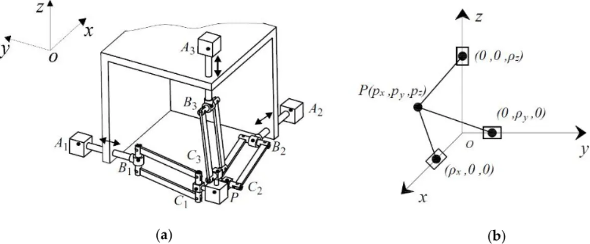
This paper deals with the shaking force balancing problem of the Orthoglide [18,19] via the last-mentioned approach taking into consideration the robot structure. The robot Orthoglide is a three-degrees-of-freedom parallel manipulator with regular workspace and good compactness. Its three actuators are arranged according to the Cartesian coordinate space. The prototype and architecture of the robot are shown in Figures 2 and 3.
Figure 2. The prototype of the Orthoglide (LS2N).
Here we point out that this paper is an extended version of a work first published at the 29th International Conference on Robotics in Alpe-Adria-Danube Region (RAAD 2020) [20]. With regard to [20], additional simulation results are presented here, i.e., the balancing of shaking force taking into account the varying payload and its sensitivity analysis. The rest of the paper is organized as follows: Section 2 describes the balancing approach based on optimal motion planning of the common center of mass; In Section 3, the numerical simulations in ADAMS software are conducted to validate the efficiency of the proposed balancing approach and the sensitivity to the design variables.
Now, let us consider the shaking force balancing of the Orthoglide.
2. Shaking force Balancing of the Orthoglide
2.1. Problem formulation
Let us first consider the kinematic architecture of the Orthoglide (Figure 3(a)). It consists of three identical kinematic chains that are formally described as PRP Ra , whereP, Rand Padenote
the actuated prismatic, revolute, and parallelogram joints respectively. The mechanism input is made up by three actuated orthogonal prismatic joints. The output body is connected to the prismatic joint through a set of three kinematic chains. Inside each chain, one parallelogram is used and oriented in a manner that the output body is restricted to translational movements only. The three parallelograms have the same lengthsLB Ci i. The arrangement of the joints in the PRP Ra
chains has been defined to eliminate any constraint singularity in the Cartesian workspace. Each frame pointAiis fixed on the
i th
linear axis so thatA A1 2A A1 3A A2 3. The pointsBi andCiarelocated on the
i th
parallelogram, as is shown in Fig. 1. The reference frame is located at the intersection of the prismatic joint axes and aligns the coordinate axis with them. The details of the design of the Orthoglide and its optimization can be found in [18,19].(a) (b)
Figure 3. (a) The structure of the Orthoglide; (b) The geometrical model of the Orthoglide
For the Orthoglide geometrical model (see Figure 3(b)), the inverse kinematic equations [21] can be drives in a straightforward way as:
2 2 2 2 2 2 2 2 2 x x x y z y y y x z z z z x y p s L p p p s L p p p s L p p (1)
where sx, sy, sz are the configuration indices that are equal to 1; The input vector of the three
prismatic joints variables as ρ ( ,
x y, z) and the output position vector of the tool center point as p(p p px, y, z). Note that for the Orthoglide robot, a single inverse kinematic solution is reachable.The shaking forces
F
shof mechanisms can be written in the form:( ) sh payload m m F s&& (2) where 1 n i i m m
is the total mass of the moving links of the manipulator, mpayloadis the mass of thepayload and
s&
&
is the acceleration of the total mass center. In the proceeding of 29th InternationalConference on Robotics in Alpe-Adria-Danube Region, the balancing problem of the Orthoglide has been addressed without counting the varying payloadmpayload. As mentioned above (in section 1), the
shaking force balancing via mass redistribution consists in adding counterweights in order to keep the total mass center of moving links stationary [22]. In this case,
s&
&
0
for any configuration of the manipulator and, as a result, the shaking force is cancelled. It is obvious that the adding of supplementary masses as counterweights is not desirable because it leads to the increase of the total mass, of the overall size of the manipulator, the efforts in joints, the shaking moment and the input torques. Therefore, in the present study, it is proposed to minimize the shaking force via reduction of the total mass center acceleration:( ) max min s t s && (3)
i.e. to apply an optimal control of the total mass center of moving links that allows one to reduce the maximal value of its acceleration.
For this purpose, let's consider the control of the spatial parallel manipulator Orthoglide through the motion planning of its center of mass. To ensure it, let us assume that the center of mass
moves along a straight line between its initial and final positions. Thus, the motion profile used on this path will define the values of shaking forces. For the same displacement of the total center of mass Sand the displacement timetf , the maximal value of the acceleration changes following the
motion profile [23]: For quantic polynomial profile, the 2 max 10 3
a S t ; For bang-bang profile,
2 max 4
a S t . It means the application of bang-bang law theoretically brings about a reduction of 30.7% of the maximal value of the acceleration. Hence, to minimize the maximum value of the acceleration of the total mass center and, as a result, shaking forces, the “bang-bang” profile should be used. Thus, by reducing the acceleration of the center of mass of the Orthoglide, a decrease in its shaking forces is achieved. Therefore, to achieve the shaking force balancing through the approach described above, it is necessary to consider the relationship between the input parameters
(
x, y, z)
ρ and the center of mass positionsP(p p px, y, z)of the Orthoglide.
2.2. The relationship between the total center of mass and the input parameters of the robot
In order to control the manipulator according to the method described above, it is necessary to establish the relationship between the displacement of the total center of mass and the input parametersρ(
x, y, z), i.e., for the given position and the law of motion of the Common Center of Mass (COM) of the manipulator determine its input displacements. Then, by means of the obtained input parameters via forward kinematics determine the position of the output axis(p p px, y, z)
P . For this purpose, it is necessary to establish the relationship between the common center of mass of the manipulator and its input parameters.
Let us start this issue with the initial and final positions P(p p px, y, z) of the platform ( ,x y zi i, )i
i
P and Pf(xf,y zf, f). So, by invers kinematics [21], the input angles corresponding to these positions will be determined: ρi(
xi, yi, zi)and ρf(
xf, yf, zf). The corresponding values of the common COM of the manipulator can also be found: SCOM_i (xSi,ySi,zSi) and SCOM_f (xSf, ySf,zSf). The displacement of the total center of mass is D(d d dx, y, z)SCOM_f- SCOM_i. Subsequently, a
straight line connecting the initial and final positions of the comment center mass of the manipulator can be established and its motion planning by “bang-bang” profile with the time interval tf can be
ensured: SCOM S
t , i.e.2 2 2( ) , (0 ) 2 ( ) 1 4( ) 2( ) , ( ) 2 f f f f f f t t t t t t t t t t t t COM_i COM_i S D S S D (4)
Let us now consider the relationship between SCOM
x t y t z t( ), ( ), ( )
and the input displacement(
x, y, z)
ρ .
The common COM of the manipulator can be expressed as:
1 n i payload i m m M
i P COM r r S (5)where i is the number of the moving link
i 1, ,n
, SCOM is the coordinate vector of the totalmass center of the manipulator, riis the the coordinate vector of the linkagei, miis the mass of the
linkagei; rPis the the coordinate vector of the payload, mpayload is the mass of the payload;
1 n i payload i M m m
In the developed prototype, the slider of prismatic joint is designed as bodyAB, whereAis not on the three axes but has an offset named
l
. At the same time, C1C2C3P. Thus, the coordinates of the joints along X, Y and Z axes are the followings:X-axis : C1(p px, y,pz); B1(x, 0, 0); A1(xl, 0, )l .
Y-axis : C2 (p p px, y, z); B2 (0,
y, 0); A2 ( ,l
yl, 0).Z-axis : C3(p p px, y, z); B3(0, 0,z); A3(0, ,l zl).
The mass centers of the parallelograms can be written as:
0.5 , 0.5 , 0.5 i i i i i i C B C B C B x x y y z z , and their masses are m1. The masses center of the three actuated links are: 0.5
, 0.5
, 0.5
i i i i i i
A B A B A B
x x y y z z
, the masses of input links are denoted
asm2. The coordinates of the mass center of the joint of end-effector P are(p p px, y, z) and its mass
is m3.
With the masses of the corresponding links, the expressions of the total center of mass of the moving links of the Orthoglide can be expressed as:
1 2 3 1 2 3 1 2 3 0.5 3 ( ) ( ) 0.5 3 ( ) ( ) 0.5 3 ( ) ( ) x x x x payload x y y y y payload y z z z z payload z S m p m l m m p M S m p m l m m p M S m p m l m m p M (6)where,M 3(m1m2)m3mpayloadis the total mass of the moving components.
According to the proposed method, the displacement of the total center of mass should follow Bang-bang motion profileS( )t , i.e.
2 2 2 2 2 2( ) , (0 ) 2 ( ) 1 4( ) 2( ) , ( ) 2 2( ) , (0 ) 2 ( ) 1 4( ) 2( ) , ( ) 2 2( ) , (0 ) 2 ( ) 1 4( ) 2( f Si x f f Si x f f f f Si y f f Si y f f f f Si z f Si f t t x d t t x t t t t x d t t t t t t y d t t y t t t t y d t t t t t t z d t t z t t t z t t )2 , ( ) 2 f z f f t d t t (7)
Note that the output parameters (p p px, y, z) of the manipulator Orthoglide can be expressed with
the functions including the input parameters(
x, y, z) via direct kinematics [21]. Thus, Equation(6) becomes a group of three equations expressed with three unknowns(
x, y, z)and it has a unique solution. Finally, the time-varying input displacements of the actuated prismatic joints can be obtained in order to ensuring the displacement of the COM.3. Illustrative example via CAD model
To validate the proposed method, numerical simulations are conducted in ADAMS software. We created a CAD model and carry out the simulations by applying the following parameters of the Orthoglide [24] which correspond to the geometrical parameters of the prototype developed in LS2N (Figure 1). The detailed geometric parameters are: the length of the longer side of the three
parallelograms isLB C1 1B C2 2B C3 30.31m, the configuration indices of the current mechanism aresxsy sz 1. The masses of sliders are: m10.396kg, the masses of the parallelograms are
2 0.248
m kg and the mass of the revolute jointPism30.1kg. The trajectory of the output axis P of the platform is given by its initial position Pi with the coordinates:xi0, yi0,zi 0 and the
final position Pf with the coordinates:
x
f
0.1
m
, yf0.07m,zf 0.11m. The correspondinginput displacements are determined via inverse kinematics:
xi 0.31m,
xf 0.18m,
yi 0.31m, 0.34yf m
,
zi0.31m,
zf 0.17m. The coordinates of the common COM of the manipulator fortwo positions have been found: xSi 0.04m, ySi 0.04m,zSi0.04m ,xSf 0.04m , ySf 0.09m , 0.05
Sf
z m. The traveling time of this trajectory is tf 0.1s, the designed acceleration of the center of mass is 2
38.7 / com
a m s .
3.1. Balancing of the Orthoglide without taking into account the payload
The traditional control strategy based on the trajectory and motion planning of the end-effector. In the application of the pick-and-place robot, the displacement of the end-effector is defined as a straight line and parameterized with a motion profile such as a quantic polynomial profile. With the proposed approach in this paper, the trajectory of the end-effector is not defined but the trajectory of the COM. Then, the “bang-bang” motion profile is applied to the trajectory of the COM. Thus, in this section, three studied cases are designed in order to see the efficiency of the proposed method:
Case 1: Defining the displacement of the end-effector of the unbalanced manipulator as a straight line and parameterized with “fifth-order polynomial” profile;
Case 2: Defining the displacement of the end-effector of the unbalanced manipulator as a straight line and parameterized with “bang-bang” profile;
Case 3: The generation of the motion via defining the displacement of the manipulator center of mass as a straight line and parameterized with “bang-bang” profile.
By comparing Cases 1 and 2, we can see the necessity of using “bang-bang” law; by comparing Cases 2 and 3, the advantage of COM motion planning become obvious; in comparison of Cases 1 and 3, the difference between the traditional control method and proposed one becomes evident.
(a) (b)
Figure 4. (a) Variations of shaking forces for three studied cases; (b) Variations of shaking moments
for three studied cases.
The simulation results (Figure 4(a)) show that, compared to the traditional control technique (Case 1), the shaking force has been reduced up to 33.2% by applying “Bang-bang” law to the COM (Case 3) without carrying a payload. Employing the “Bang-bang” motion on the end-effector (Case 2) reduces the shaking force by 24.9%. Obviously, the motion control of the COM of the Orthoglide is more efficient.
Compared to the increase of the shaking moment of the balancing method based on adding counterweights, the shaking moment (see in Figure 4(b)) has a reduction of 33.6% with the approach based on the motion planning of the COM (Case 3). The method that defines the motion of the end-effector with “bang-bang” (Case 2) motion profile reduces the shaking moment by 23.8%.
Another advantage of this method is its simplicity and versatility. In the case of changing trajectory, it is just necessary to provide the initial and final coordinates of the end-effector, calculate the input parameters according to the proposed method and implemented in the manipulator control system.
3.2. Balancing of the Orthoglide while taking into account the payload
With the balancing method by adding counterweights, once the payload changed, the mass redistribution needs to be redone, which brings about the complexity of the balancing process.
However, the proposed approach by optimal motion planning of the COM is still efficient taking into account the varying payload because the motion planning can be conducted without modifying the robot components and configuration. In view of the payload capacity of the Orthoglide (5kg), Table 1 and Table 2 demonstrate the shaking force and shaking moment for three cases when the Orthoglide is carrying a payload. The variations and reduction ratio of the shaking force and the shaking moment taking into account the payloads are respectively presented in Table 1 and Table 2.
Table 1. The shaking force and its reduction of the Orthoglide while carrying a payload
Mass of payload / kg
Shaking force1 / Newton Reduction2 / %
Case 1 Case 2 Case 3 Case2 Case3 0 117.99 88.56 78.86 24.9 33.2 1 212.08 152.82 144.57 27.9 31.8 2 306.73 218.08 210.55 28.9 31.3 3 401.55 283.65 276.31 29.3 31.2 4 496.43 349.36 342.22 29.6 31.1 5 591.35 415.14 408.14 29.8 30.9
1The maximum value of the shaking force during the movement
2The reduction ratio of shaking force is calculated by 2 1 3 1
1 1
Case Case Case Case and
Case Case
.
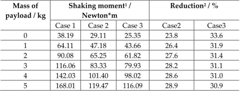
Table 2. The shaking moment and its reduction of the Orthoglide while carrying a payload
Mass of payload / kg
Shaking moment1 /
Newton*m
Reduction2 / %
Case 1 Case 2 Case 3 Case2 Case3 0 38.19 29.11 25.35 23.8 33.6 1 64.11 47.18 43.66 26.4 31.9 2 90.08 65.25 61.82 27.6 31.4 3 116.06 83.33 79.93 28.2 31.1 4 142.03 101.40 98.02 28.6 31.0 5 168.01 119.47 116.09 28.9 30.9 1The maximum value of the shaking moment during the movement
2The reduction ratio of shaking moment is calculated by 2 1 3 1
1 1
Case Case Case Case and
Case Case
.
As is shown in Table 1, the shaking force of the Orthoglide has been reduced up to 33.2%. Following the increase of the payload, the reduction ration is approaching the theoretical value 30.7%. Thus, we have the conclusion that, with the proposed balancing approach, a minimum reduction (30.7%) of the shaking force can be achieved. Compared to Case 3, Case 2 has a minimum reduction of the shaking force of 24.9%.
It should be noted that the purpose of these simulations was not an illustration of the decrease in the shaking moment. However, it was considered useful to give the simulation results, which show that a decrease in shaking force is accompanied by a decrease in shaking moment. It can be considered a further advantage of the suggested balancing solution.
3.3. Sensitivity analysis of the shaking force and shaking moment
In the current industry, manufacturing errors are unavoidable and should be considered during the design process in order to ensure high accuracy of achieved results. With the proposed balancing strategy, the mass of the payload is one of the design variables, which can largely influence the final values of shaking forces and shaking moments acting on the frame. During the balancing process, if a mass error exists, the balancing condition can be different. Thus, we assume that the error presents. Then, two cases are designed in order to evaluate its sensitivity:
Case 3: balancing by optimal motion planning with “bang-bang” law taking into account the mass error;
Case 4: balancing by optimal motion planning with “bang-bang” law without taking into account the mass error.
By comparing Case 3 and 4, the errors of shaking force and shaking moment to the payload can be obtained.
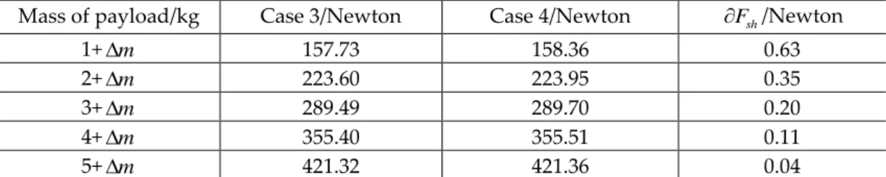
Table 3. Maximal value of the total shaking force of the robot taking into account the mass error of
the payload
Mass of payload/kg Case 3/Newton Case 4/Newton Fsh/Newton
1+m 157.73 158.36 0.63 2+m 223.60 223.95 0.35 3+m 289.49 289.70 0.20 4+m 355.40 355.51 0.11 5+m 421.32 421.36 0.04 sh F
is the difference of the shaking force between the Case 4 and Case 3.
Table 4. Maximal value of the total shaking moment of the robot taking into account mass error of
the payload
Mass of payload/kg Case 3/Newton*m Case 4/Newton*m Msh/Newton*m
1+m 47.30 47.74 0.43 2+m 65.44 65.75 0.30 3+m 83.55 83.78 0.23 4+m 101.63 101.82 0.19 5+m 119.70 119.86 0.16 sh M
is the difference of the shaking moment between the Case 4 and Case 3.
The simulation results given in Table 3 and Table 4 show the variations of shaking force and shaking moment. As we can see, both shaking force and shaking moment are not very sensitive to the payload’s variations, which means the proposed balancing solution has good stability even under manufacturing errors. Following the increase of the payload, the difference between Cases 3
and 4 is reducing, which indicates that the mass error of the payload carried by the Orthoglide can be ignored.
4. Conclusion
It is known that the shaking force balancing by counterweights mounted on the moving links is more appropriate for serial and planar parallel manipulators. It is much more difficult for spatial parallel manipulators. Therefore, in this paper, an alternative method based on optimal acceleration control of the common COM is applied for shaking forces minimization of the Orthoglide robot. The suggested balancing technique consists in the fact that the Orthoglide is controlled not by applying platform trajectories but by motion planning of the total mass center of moving links. The trajectories of the total mass center of the manipulator are defined as straight lines and are parameterized with “bang-bang” profile. Such a control approach allows the reduction of the maximum value of the center of mass and consequently the shaking force. The numerical simulations show the efficiency of the proposed solution.
Future works concern now the experimental validation of the suggested balancing technique via tests that will be carried out on the prototype of the Orthoglide developed in LS2N (Figure 2).
Author Contributions: Conceptualization, methodology and investigation, software, validation, data curation,
writing–original draft preparation, writing–review and editing, G.J., A.V., C.D. and L.P. All authors have read and agreed to the published version of the manuscript.
Funding: This research was supported by a scholarship funded by the China Scholarship Council. Conflicts of Interest: The authors declare no conflict of interest.
References
1. Filaretov, V.F., Vukobratovic, M.K.: Static balancing and dynamic decoupling of the motion of manipulation robots. Mechatronics 1993, 3(6), pp. 767-783.
2. Bayer, A., Merk, G.: Industrial robot with a weight balancing system 2009; EP Patent 2 301 727.
3. Gosselin CM.: Gravity compensation, static balancing and dynamic balancing of parallel mechanisms. In: SmartDevices and Machines forAdvanced Manufacturing. Springer, London, 2008; pp 27–48
4. Agrawal, S.K, Fattah, A.: Reactionless space and ground robots: novel design and concept studies. Mechanism and Machine Theory 2004, 39(1), pp. 25-40.
5. Fattah, A., and. Agrawal, S.K.: Design and modeling of classes of spatial reactionless manipulators. In: 2003 IEEE International Conference on Robotics and Automation (ICRA); IEEE, Taipei, 2003; pp. 3225-3230.
6. Fattah, A., and. Agrawal, S.K.: Design arm simulation of a class of spatial reactionless manipulators. Robotica 2005, 23(1), pp. 75-81.
7. Wijk, V. van der, and Herder, J. L.: Dynamic Balancing of Clavel’s Delta Robot. In: Kecskeméthy A., Müller A. (eds); Computational Kinematics; Springer, Heidelberg, 2009; pp. 315–322.
8. Alici G. and Shirinzadeh, B.: Optimum force balancing with mass distribution and a single elastic element for a five-bar parallel manipulator. In: 2003 IEEE International Conference on Robotics and Automation (ICRA); IEEE, Taipei, 2003; pp. 3666-3671.
9. Alici, G. and Shirinzadeh, B.: Optimum force balancing of a planar parallel manipulator. Proceedings of the Institution of Mechanical Engineers, Part C: Journal of Mechanical Engineering Science, 2003, 217(5), pp. 515–524.
10. Ouyang, P. R., and Zhang, W. J.: A Novel Force Balancing Method for Real-Time Controllable Mechanisms. In: ASME 2002, 27th Biennial Mechanisms and Robotics Conference; Montreal, 2002; pp. 183–190.
11. Briot, S., Arakelian, V., and Le Baron, J.-P.: Shaking Force Minimization of High-Speed Robots via Center of Mass Acceleration Control. Mechanism and Machine Theory 2012, 57, pp. 1–12.
12. Briot, S., Arakelian, V., Sauvestre, N., and Baron, J.-P. L.: Shaking Forces Minimization of High-Speed Robots via an Optimal Motion Planning. In: ROMANSY 18 Robot Design, Dynamics and Control; Springer, Vienna, 2010; pp. 307–314.
13. Arakelian, V.: Design of Partially Balanced 5R Planar Manipulators with Reduced Center of Mass Acceleration (RCMA). In: Parenti-Castelli V., Schiehlen W. (eds); ROMANSY 21 - Robot Design, Dynamics and Control; Springer, Udine, 2016, vol 569; pp. 113–122.
14. Arakelian, V., Geng, J., and Fomin, A. S.: Minimization of Shaking Loads in Planar Parallel Structure Manipulators by Means of Optimal Control. Journal of Machinery Manufacture and Reliability 2018, 47(4), pp. 303–309.
15. Geng, J., and Arakelian, V.: Design of Partially Balanced Planar 5R Symmetrical Parallel Manipulators via an Optimal Motion Planning. In: Uhl, T. (eds) Advances in Mechanism and Machine Science. IFToMM 2019; Springer, Krakow, 2019, vol 73, pp. 2211–2220.
16. Geng J., Arakelian V.: Partial Shaking Force Balancing of 3-RRR Parallel Manipulators by Optimal Acceleration Control of the Total Center of Mass. In: Kecskeméthy A., Geu Flores F. (eds) Multibody Dynamics 2019, ECCOMAS 2019, Computational Methods in Applied Sciences; Springer, Cham, 2019, vol 53, pp. 375-382.
17. Geng, J., and Arakelian, V.: Balancing of Planar 5R Symmetrical Parallel Manipulators Taking into Account the Varying Payload. In: Venture G., Solis J., Takeda Y., Konno A. (eds) ROMANSY 23 - Robot Design, Dynamics and Control, ROMANSY 2020, CISM International Center for Mechanical Sciences (Courses and Lectures); Springer, Cham, 2020, vol 601, pp. 372-379.
18. Wenger, P., and Chablat, D.: Kinematic Analysis of a New Parallel Machine Tool: The Orthoglide. In: Lenarčič J., Stanišić M.M. (eds) Advances in Robot Kinematics; Springer, Dordrecht, 2000; pp. 305–314. 19. Chablat, D., and Wenger, P.: Architecture Optimization of a 3-DOF Translational Parallel Mechanism for
Machining Applications, the Orthoglide. IEEE Transactions on Robotics and Automation 2003, 19(3), 403–410.
20. Geng J., Arakelian V., Chablat D., Lemoine P.: Shaking Force Balancing of the Orthoglide. In: Zeghloul S., Laribi M., Sandoval Arevalo J. (eds) Advances in Service and Industrial Robotics. RAAD 2020. Mechanisms and Machine Science; Springer, Cham, 2020, vol 84, pp 227-234.
21. Pashkevich, A., Chablat, D., and Wenger, P.: Kinematics and Workspace Analysis of a Three-Axis Parallel Manipulator: The Orthoglide. Robotica 2006, 24(1), pp. 39–49.
22. Arakelian, V., and Briot, S.: Balancing of Linkages and Robot Manipulators: Advanced Methods with Illustrative Examples. Springer, Switzerland, 2015.
23. Khalil, W., Dombre, E.: Modeling, Identification and Control of Robots. Hermès, 2003.
24. S. Guegan.; W. Khalil: P. Lemoine.: Identification of the dynamic parameters of the Orthoglide. In: 2003 IEEE International Conference on Robotics and Automation (ICRA); IEEE, Taipei, 2003; pp. 3666-3671.