HAL Id: hal-01847833
https://hal.archives-ouvertes.fr/hal-01847833
Submitted on 6 Nov 2019
HAL is a multi-disciplinary open access
archive for the deposit and dissemination of
sci-entific research documents, whether they are
pub-lished or not. The documents may come from
teaching and research institutions in France or
abroad, or from public or private research centers.
L’archive ouverte pluridisciplinaire HAL, est
destinée au dépôt et à la diffusion de documents
scientifiques de niveau recherche, publiés ou non,
émanant des établissements d’enseignement et de
recherche français ou étrangers, des laboratoires
publics ou privés.
Processing and characterization of aluminium-based
MMCs produced by gas pressure infiltration
E. Carreno Morelli, Thierry Cutard, R. Schaller, C. Bonjour
To cite this version:
E. Carreno Morelli, Thierry Cutard, R. Schaller, C. Bonjour. Processing and characterization of
aluminium-based MMCs produced by gas pressure infiltration. MATERIALS SCIENCE AND
EN-GINEERING. A, STRUCTURAL MATERIALS, 1998, 251 (n° 1-2), p. 48-57.
�10.1016/S0921-5093(98)00649-2�. �hal-01847833�
Processing and characterization of aluminium-based MMCs
produced by gas pressure infiltration
E. Carren˜o-Morelli
a,*, T. Cutard
1,a, R. Schaller
a, C. Bonjour
baEcole Polytechnique Fe´derale de Lausanne, Institut de Ge´nie Atomique, PHB-E´cublens, CH-1015 Lausanne, Switzerland bEcole d’Inge´nieurs du Valais, route de Rawyl 47, CH-1950 Sion, Switzerland
Abstract
A device has been designed and built for unidirectional infiltration of ceramic preforms with a molten metal. It allows production of Al or Mg alloys reinforced with short or continuous ceramic fibres. The apparatus has been tested for different alloys and preforms by varying the process parameters (infiltration pressure, fibre content, melt superheat, preform preheat and solidification speed). As an example, full infiltration of Al2O3–SAFFIL chopped preforms with an Al–4wt.%Cu–1wt.%Mg–
0.5wt.%Ag alloy has been achieved under controlled conditions by using a gas pressure between 1 and 3 MPa. The resulting metal matrix composite has been characterised by microscopical observations and mechanical tests. Measurements of Young’s modulus, density, microhardness and mechanical loss show that the optimal process conditions for Al–4wt.%Cu–1wt.%Mg–0.5wt.%Ag– SAFFIL composites are a temperature of 750°C for both preform and melt and the maximum infiltration pressure of 3 MPa. Preliminary tests have shown that the gas pressure infiltration apparatus is also suitable to produce continuous fibre reinforced and hybrid metal matrix composites.
Keywords: Aluminium; Gas pressure infiltration; Magnesium; Metal-matrix composites
1. Introduction
Liquid metal infiltration of ceramic preforms is a usual route to produce metal matrix composites (MMCs) [1,2]. In particular, squeeze casting provides good infiltration quality of chopped preforms [3,4]. This procedure consists of pushing the molten metal into a preheated preform using a piston and pres-sures in the range 50–100 MPa. Despite the good results obtained with this technique, some difficulties remain related with air entrapment into the preform [5,6] which can be at the origin of voids at metal– ceramic interphases, with detrimental consequences to the mechanical properties. An additional problem is related to the high pressure involved in the process, which implies the development of heavy equipment even for laboratory research. Moreover, high
pres-sure could produce fibre damage or an inhomoge-neous fibre distribution along the infiltration direction [3].
In order to overcome these problems, special at-tention has been devoted to low pressure infiltration processes [7–10]. With respect to squeeze casting, the infiltration pressure can be substantially reduced if the vacuum is made in the preform to avoid air en-trapment [11]. Consequently, relatively low-cost facili-ties can be developed using a gas pressure to achieve infiltration. In this work, a prototype of a gas pres-sure infiltration device which has been developed for MMCs processing at the laboratory scale is pre-sented. This prototype is based on the idea that al-loy melting and preform infiltration should be done separately. Consequently, the apparatus is divided into two parts: a melting chamber, where the alloy is melted under vacuum or protective atmosphere, and an injection chamber, where the molten metal is pushed into the preform by gas pressure. The two chambers are isolated from each other by a high pressure valve.
* Corresponding author. Tel.: +41 21 6933708; fax: +41 21 6934470; e-mail: [email protected]
1Present address: Ecole des Mines d’Albi-Carmaux, Centre Mate´ri-aux, F81013 Albi, France.
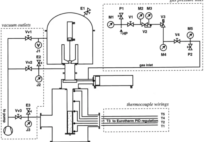
Fig. 1. Schematic drawing of the gas pressure infiltration device showing the melting and the vacuum chambers. The high pressure valve allows one to isolate the melting chamber from the injection chamber (which is inside the vacuum chamber).
2. Experimental
2.1. Gas pressure infiltration de!ice: description and
operation
Fig. 1 shows a schematic drawing of the gas pressure infiltration apparatus where four major parts can be distinguished:
1. the melting chamber 2. the vacuum chamber
3. the injection chamber inside the vacuum chamber 4. the high pressure valve which allows one to isolate
the melting and the injection chambers.
Vacuum can be achieved independently in each chamber as shown in Fig. 2 (using vacuum outlets Vv1, Vv2 and Vv3). The melting chamber is equipped with a Leybold ISG 0,5 (Leybold GmbH, Ko¨ln, Germany) commercial induction furnace. The alloy is melted in a graphite crucible, the bottom of which is closed by an actuator-controlled graphite finger. The melt heating is monitored by a thermocouple located inside the graphite finger.
The vacuum chamber provides isolation of the injec-tion chamber during preform preheating, casting and solidification. Actually, both the vacuum and injection chambers are connected by a 1 mm diameter conduct which allows one to continue with the preform outgas-ing even duroutgas-ing castoutgas-ing. In addition, this avoids any possibility of gas entrapment into the preform.
The injection chamber is composed of a cylindrical high pressure vessel made of a high temperature refrac-tory alloy (Haynes 230 Ni–Cr–W alloy, from Nickel-Contor, Zu¨rich, Switzerland) and of an inner graphite (type R8650 from Steinemann AG, Chur, Switzerland) mould in which the preform is located. The preform is rod-shaped with a slightly conical geometry in order to facilitate its extraction through the bottom entry port of the mould. The preform can be pre-heated up to
800°C by a THERMOCOAX® (Philips AG, Dietikon,
Switzerland) heater wound around the injection cham-ber. Five thermocouples installed at different heights in the external wall of the injection chamber (Fig. 2) allow one to sense the evolution of the temperature, which is
Fig. 2. Schematic drawing showing the vacuum outlets (Vv1, Vv2, Vv3), the vacuum gauges (J1, J2, J3), the gas inlet with the hand driven valve V4, and thermocouple wirings.
Fig. 3. Operation in the gas pressure infiltration device: (a) melting, (b) casting, (c) gate valve closing, (d) injection, (e) de-moulding. Table 1
Summary of infiltration parameters
Fibre content [% vol.]
Specimen Infiltration pressure [MPa] Melt superheat [°C] Preform preheat [°C]
1 A 15 780 755 B 15 2 780 755 C 15 3 780 755 2 780 15 750 D 25 E 3 780 750 3 750 F 25 750 3 750 25 700 G
Table 2
Density, Young’s modulus and mechanical loss maximum height for Al–4wt.%Cu–1wt.%Mg–0.5wt.%Ag reinforced with 25vol.%SAFFIL processed with different fabrication parameters
tg !max[10−3] Melt superheat [°C] Preform preheat [°C] "[g cm3] E [GPa]
Specimen Infiltration pressure [MPa]
780 750 2.81 86.8 3.9 D 2 3 780 750 2.88 86.5 E 7.3 750 750 3 2.92 F 96.0 11.2 700 750 88.5 6.7 3 2.90 G
computer-monitored during the operation. The central thermocouple T3 is connected to a Eurotherm 902P (Eurotherm, Durrington, West Sussex, England) con-troller which ensures the temperature regulation during preform preheating. After infiltration the preform is cooled down by a forced cold air stream which flows in a helical circuit around the injection chamber. Different
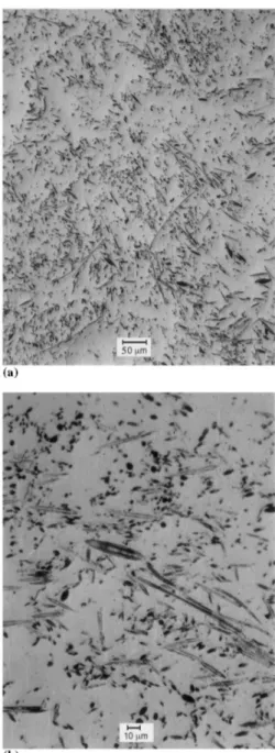
Fig. 5. Optical micrographs of Al–4wt.%Cu–1wt.%Mg–0.5wt.%Ag reinforced with 15vol.%SAFFIL processed with an infiltration pres-sure of 2 MPa.
Fig. 4. Macrograph of the as-processed MMC rod after gas pressure infiltration.
solidification speeds can be obtained by varying the air flux or the air temperature. The cooling time to room temperature is about 15×103 s for free cooling, and
can be reduced to 5×10³s by using the cold air stream.
The high-pressure valve which separates the injection chamber from the melting chamber is a vacuum gate valve specially reinforced to work under pressures as high as 5 MPa. Closing and opening movements are made by an electro-pneumatic actuator. A graphite guide is placed between the crucible and the mould in order to protect the valve and to guide the metal into the mould. The high pressure valve allows one to restrict the high pressure zone to the small volume of the mould.
The principle of operation is shown schematically in Fig. 3. As a first step, vacuum (!1 Pa) is pulled in both the melting and injection chambers. The infiltrant metal is melted in the graphite crucible of the upper chamber by high frequency heating (a). Simultaneously, in the injection chamber the preform is preheated and
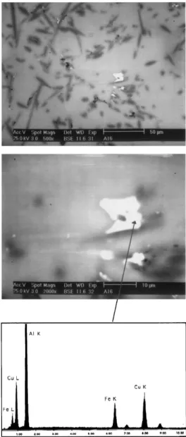
Fig. 7. Segregation of an Al–Cu–Fe phase around an Al2O3 fibre (EDS microanalysis).
Fig. 6. SEM micrographs of Al–4wt.%Cu–1wt.%Mg–0.5wt.%Ag reinforced with 15vol.%SAFFIL (a) as-cast and (b) after solution treatment of 2 h at 480°C+2 h at 500°C.
outgassed. When the desired temperature of the molten metal as well as of the fibre preform are reached, the power for the preform preheating is switched off and the graphite finger is opened, allowing flow of the molten metal from the upper to the lower chamber (b). Then, the gate valve is closed (c) and argon is rapidly introduced until the desired pressure is reached in order to push the metal into the preform (d). Immediately thereafter, the casting is cooled by activation of the forced air stream. After solidification, the gas pressure is released by opening the pressure release valve P2 (see Fig. 2). When room temperature is reached, the result-ing MMC rod is extracted by openresult-ing the bottom ports of both the vacuum and injection chambers (e).
Special attention is paid to minimizing the contact time between the molten metal and the ceramic rein-forcement, in order to reduce the interphase reactions
which could lead to composite strength degradation [7]. The time between the opening of the graphite finger and the activation of the forced air stream is about 10 s. From the monitored temperatures T1 and
T2 measured in the external wall of the injection
chamber, an upper limit of 120 s can be estimated for the contact time. This is about one half of the corre-sponding value for free cooling.
2.2. Processing route. An example: Al–4wt.%Cu– 1wt.%Mg–0.5wt.%Ag reinforced with Al2O3 short
Saffil fibres
2.2.1. Preforms
The reinforcing SAFFIL #-Al2O3 fibres were
pro-duced by ICI (UK) with nominal dimensions of 3–6 !m diameter and 40–100 !m length. Pseudo ran-domly oriented preforms of 15 and 25% fibre volume fraction were provided by Vernaware, UK. Preforms result from a slurry of SAFFIL fibres and silica binder which are compressed in a mould. As a result of the fabrication process, the fibre axis tend to be aligned normal to the pressing direction, which results in a two-dimensional random arrangement. Rod-shaped preforms for gas pressure infiltration (20 mm diameter, 120 mm length) were machined from the as-received preforms (size of 153 mm×153 mm×25 mm).
2.2.2. Infiltration parameters
Systematic production of Al–4wt.%Cu–1wt.%Mg– 0.5wt.%Ag reinforced with SAFFIL short fibres has been made by varying the infiltration parameters in order to optimize the production process (see Table 1). The process variables were the fibre content [15– 25% vol.], the preform preheat [700–750°C], the melt superheat [700–800°C] and the infiltration pressure [1–3 MPa]. In order to reduce the contact time be-tween molten metal and fibres, the maximum cooling speed after injection was used in all experiments. This was accomplished by setting the air flux to the maxi-mum and by cooling the air in a liquid nitrogen bath before its entrance to the vacuum chamber. After processing, different thermal treatments were made for the as-cast specimens in order to identify condi-tions for an optimal mechanical behaviour.
2.2.3. Characterization
Optical and scanning electron microscopy were used to evaluate the infiltration quality, segregation, porosity and grain distribution. Specimens for metal-lographic observation were prepared by grinding through 600 grit papers followed by polishing with 6 !m and 3 !m diamond paste. The grain structure was revealed by chemical etching in a solution of 3 ml HCl, 5 ml HNO3, 2 ml HF, 190 ml H2O followed
by lightly swabbing with a solution of 20% NO3
fum-ing/80% H2O to remove oxidation. The chemical
composition of segregated products at interfaces was determined by EDS microanalysis in a Philips XL 30 FEG scanning electron microscope.
Mechanical properties were evaluated by measure-ment of Young’s modulus (E), density ("), micro-hardness (HV) and mechanical loss spectra [12]. Young’s modulus was measured in a resonant bar apparatus which allows one to tune the resonant fre-quency f (!kHz) in flexural mode for specimens of 4×1×50 mm. E is given by:
E= 0.971l
4
a2"f2 (1)
where l and a are the length and thickness of the specimen. Density measurements were made by com-paring the weight of the samples immersed in air and water, and using the Archimedean principle. Micro-hardness testing was carried out with a Leitz Durimet apparatus using a Vickers indenter and a load of 500 g. For each microhardness measurement, five indenta-tions were made and the average was used for calcu-lating the Vickers hardness number (HV). Mechanical loss spectra as a function of the temperature (tg ! versus T) were measured in an inverted torsion pen-dulum with forced oscillations during controlled heat-ing and coolheat-ing cycles between 100 and 450 K. Typical oscillation frequencies f= 0.1 Hz, strain am-plitudes $= 10− 5 and temperature change rates dT/
dt= 2 K min− 1 were used.
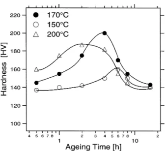
Fig. 8. Microhardness tests for Al–4wt.%Cu–1wt.%Mg–0.5wt.%Ag reinforced with 25vol.%SAFFIL, after solution treatment of 2 h at 480°C+2 h at 500°C, water quenching and natural ageing of 4 days at room temperature.
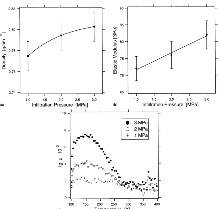
Fig. 9. Normalised density, Young’s modulus and mechanical loss spectra for Al–4wt.%Cu–1wt.%Mg–0.5wt.%Ag reinforced with 15vol.%SAFFIL, processed with different infiltration pressures (specimens A, B and C, Table 1).
3. Results
Optical examination (Fig. 4) revealed a quite uniform grain structure along the MMC castings (rods of 20 mm diameter by 120 mm length). Only a 20 mm region at the bottom shows a columnar grain structure coming from the outset of solidification. Effectively, the air cooling circuit has been mounted so as to induce direc-tional solidification from the bottom to the top of the preform. Grain size along castings seems to be con-trolled by the isotropic fibre arrangement [3].
No evidence of the presence of cavities at interfaces nor in the matrix was found with optical microscopy,
which shows that full infiltration of the ceramic pre-form was obtained using the present gas pressure infiltration process (Fig. 5).
Scanning electron microscopy shows in the as-cast structure the existence of a segregated phase around the fibres (Fig. 6a) which have been identified as Al2Cu
from EDS microanalysis. This phase, which is not desirable for mechanical properties, is almost com-pletely dissolved after a two-stage solution treatment of 2 h at 480°C+2 h at 500°C (Fig. 6b). However, residual segregation persists due to the presence of iron as shown in Fig. 7. Iron is certainly present in the aluminium alloy before infiltration, since during the
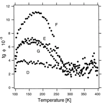
Fig. 10. Mechanical loss spectra for Al–4wt.%Cu–1wt.%Mg– 0.5wt.%Ag reinforced with 25vol.%SAFFIL, processed with different fabrication parameters; f= 0.1 Hz, $= 10− 5, dT/dt= 2 K min− 1, coolings. (Letters refer to Table 2).
Fig. 11. Optical micrographs of polished sections from Mg–2wt.%Si– Carbon composites (a) parallel and (b) normal to the fibre direction. The white arrow indicates the infiltration direction. Precipitates of the Mg2Si phase are observable between the C fibres.
infiltration process, the molten metal is never in contact with a metallic part that contains iron. Microhardness tests made in solution treated, water quenched and aged specimens show that the peak aged condition is obtained after artificial ageing of 4 h at 170°C (Fig. 8). This annealing time is certainly shorter than in the non-reinforced alloy as demonstrated by Parrini et al. [13] in the case of the Al–4wt.%Cu matrix.
The existence of micropores in the as-processed Al-based MMCs is revealed by the measurements of the density (Fig. 9a) and of the elastic Young’s modulus (Fig. 9b) which suggest that the microporosity is the lowest for the highest infiltration pressure (3 MPa) as expected. The behaviour of the mechanical loss maxi-mum at 200 K during thermal cycling is in good agreement with this presumption (Fig. 9c). Effectively, this maximum has been attributed to dislocation cre-ation and motion near the interfaces originated in the thermal expansion mismatch between matrix and fibres [14–16]. Then, because cavities reduce the interfacial bonding strength, the lowest level of mechanical loss is expected for the highest degree of porosity. On the contrary, the best bonded interfaces should give rise to the highest mechanical loss maximum, as is the case of specimens infiltrated with a pressure of 3 MPa.
The evaluation of MMCs produced with different infiltration pressure, preform preheat and melt super-heat, shows that the best performance (highest level for density, Young’s modulus and mechanical loss maxi-mum during cooling) is obtained after infiltration at 3 MPa with melt and preform temperatures equal to
750°C (see Table 2 and Fig. 10). Other tests have revealed that for lower melt temperatures the MMC porosity was higher. This would mean that the alloy viscosity was too high to achieve full infiltration of the ceramic preform. For higher melt temperatures, the mechanical properties were lower. This can be inter-preted as due to the interface degradation by too long a contact time between the molten metal and the ce-ramic preform.
Finally, preliminary tests have been carried out to produce long fibre reinforced and hybrid MMC. Fig. 11 shows a Mg–2wt.%Si matrix composite reinforced with continuous carbon fibres. The observation of both di-rections parallel and normal to fibres, shows that a good infiltration quality is obtained. In the metallic matrix one observes precipitation of the intermetallic Mg2Si phase. In addition, full infiltration of Al–
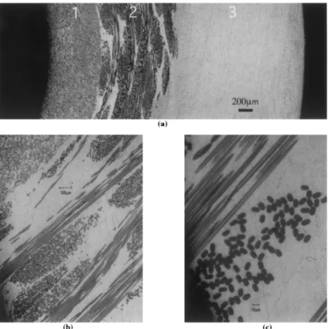
Fig. 12. (a) Optical micrographs of a hybrid MMC consisting in a core of Al–4wt.%Cu–1wt.%Mg–0.5wt.%Ag–SAFFIL (1), an interlayer of Al–4wt.%Cu–1wt.%Mg–0.5wt.%Ag–Nextel (2) and a surface layer of non-reinforced Al–4wt.%Cu–1wt.%Mg–0.5wt.%Ag (3). The observation in detail of the interlayer (b, c) shows that full infiltration of the continuous Nextel 440 fibres has been achieved.
4wt.%Cu–1wt.%Mg–0.5wt.%Ag in complex preforms made of both short SAFFIL and long Nextel 440 alumina fibres was achieved with pressures of 3 MPa. The preforms consisted in a core of SAFFIL around which the Nextel fibres were wound. After infiltration, one obtains a core of Al–4wt.%Cu–1wt.%Mg– 0.5wt.%Ag–SAFFIL surrounded by a long fibre (Nex-tel) reinforced interlayer and an non-reinforced metal surface layer. Fig. 12a shows the transverse section of a machined tube made of this hybrid composite. Details of the intermediate region are shown in the Fig. 12(b) and (c). The interest of this kind of material is to combine the high stiffness of long fibres with fatigue resistant surfaces. These developments are in progress. 4. Conclusions
A new apparatus has been developed which allows one to process MMCs by the gas pressure infiltration technique. This apparatus is composed of two parts: one melting chamber where the metallic alloy is melted under vacuum or protective atmosphere, and an injec-tion chamber for preform preheating and gas pressure infiltration. In this configuration infiltration needs a
low volume of high pressure gas, and consequently, the infiltration time is reduced and the operational safety is increased.
Al–4wt.%Cu–1wt.%Mg–0.5wt.%Ag–SAFFIL com-posites have been produced with variable process parameters and then characterised by microscopical and mechanical tests.
Optical and scanning electron microscopy show that full infiltration was obtained with infiltration pressures between 1 and 3 MPa. An optimal thermal treatment has been found for these materials. It consists of a two-stage solution treatment of 2 h at 480°C+2h at 500°C (necessary to dissolve the Al2Cu phase
segre-gated around the fibres in the as-cast structure) fol-lowed by artificial ageing of 4 h at 170°C to reach the peak aged condition.
Measurement of Young’s modulus, density, micro-hardness and mechanical loss show that the optimal
process conditions for Al–4wt.%Cu–1wt.%Mg–
0.5wt.%Ag–SAFFIL composites are a temperature of 750°C for both preform and melt and the maximum infiltration pressure of 3 MPa.
Infiltration of complex preforms consisting on an arrangement of both, short SAFFIL and long Nextel 440 fibres has been successfully achieved. In addition,
continuous reinforced Mg–2wt.%Si–C composites have been produced in preliminary tests. This features that the infiltration apparatus is suitable for the production of both continuous reinforced and hybrid MMC.
Acknowledgements
Authors specially acknowledge the technical support provided by B. Guisolan. Authors also acknowledge the support of the Centre Interde´partemental de Microscopie Electronique (CIME-EPFL) for the SEM observations. This research has been partially financed by the Swiss Priority Program on Materials Research, Project 2.1.B. References
[1] M. Taya, R.J. Arsenault, Metal Matrix Composites, Pergamon Press, Oxford, 1989, pp. 51–63.
[2] M.M. Schwartz, Composite Materials Handbook, Mc Graw-Hill, New York, 1984.
[3] T.W. Clyne, J.F. Mason, Metall. Trans. A 18 (1987) 95. [4] H. Fukunaga, K. Goda, Bull. Jpn. Soc. Mech. Engrs. 27 (1984)
1245.
[5] S. Long, Z. Zhang, H.M. Flower, Acta Metall. Mater. 43 (1995) 3489.
[6] S. Long, Z. Zhang, H.M. Flower, Acta Metall. Mater. 43 (1995) 3499.
[7] A. Mortensen, J.A. Cornie, M.C. Flemings, J. Met. 40 (1988) 12.
[8] A. Mortensen, L.J. Masur, J.A. Cornie, M.C. Flemings, Metall. Trans. A 20 (1989) 2535.
[9] L.J. Masur, A. Mortensen, J.A. Cornie, M.C. Flemings, Metall. Trans. A 20 (1989) 2549.
[10] S. Nourbakhsh, H. Margolin, F.L. Liang, Metall. Trans. A 10 (1989) 2159.
[11] S. Nourbakhsh, F.L. Liang, H. Margolin, J. Phys. E 21 (1988) 898.
[12] A.S. Nowick, B.S. Berry, Anelastic Relaxation in Crystalline Solids, Academic Press, New York, 1972.
[13] L. Parrini, R. Schaller, Acta Metall. Mater. 43 (1995) 2149. [14] A. Vincent, G. Lormand, S. Durieux, C. Girard, E. Maire, and
R. Fouge`res, J. Phys. IV, 6, coll.C8 (1996) C8–719. [15] L. Parrini, R. Schaller, Acta Mater. 44 (1996) 4881.
[16] E. Carren˜o-Morelli, S.E. Urreta, R. Schaller and L. Gabella, J. Physique IV, 6, coll.C8 (1996) C8–735.