HAL Id: hal-01703246
https://hal.archives-ouvertes.fr/hal-01703246
Submitted on 2 Jul 2018
HAL is a multi-disciplinary open access
archive for the deposit and dissemination of
sci-entific research documents, whether they are
pub-lished or not. The documents may come from
teaching and research institutions in France or
abroad, or from public or private research centers.
L’archive ouverte pluridisciplinaire HAL, est
destinée au dépôt et à la diffusion de documents
scientifiques de niveau recherche, publiés ou non,
émanant des établissements d’enseignement et de
recherche français ou étrangers, des laboratoires
publics ou privés.
A microstructural and low-cycle fatigue investigation of
weld-repaired heat-resistant cast steels
Traian Branza, F. Deschaux-Beaume, Vincent Velay, Philippe Lours
To cite this version:
Traian Branza, F. Deschaux-Beaume, Vincent Velay, Philippe Lours. A microstructural and
low-cycle fatigue investigation of weld-repaired heat-resistant cast steels. Journal of Materials Processing
Technology, Elsevier, 2009, 209 (2), pp.944-953. �10.1016/j.jmatprotec.2008.03.002�. �hal-01703246�
A microstructural and low-cycle fatigue investigation of
weld-repaired heat-resistant cast steels
T. Branza
a, F. Deschaux-Beaume
b,∗, V. Velay
a, P. Lours
aaUniversit´e de Toulouse, Mines Albi, CROMeP, Campus Jarlard, 81013 Albi, Cedex 09, France
bUniversit´e de Montpellier 2-IUT de N¨ımes, Mechanics and Civil Engineering Laboratory, 30907 Nˆımes, France
Keywords:
Heat-resistant cast steel Welding
Cracking Low-cycle fatigue
a b s t r a c t
The multi-pass weld-repair of heat-resistant cast steels is carried out using an automated shielded metal arc welding (SMAW) process, with various filler materials and pre-heating at 400◦C. Specimens weld-repaired with a filler material more resistant than the heat-resistant
cast steel (over-matching) generally crack within the base metal following the tenth filling pass, whereas specimens buttered with a soft alloy prior to welding remain free of cracks.
The high temperature strain-controlled fatigue lifetime of material weld-repaired without buttering is lower than that of bulk initial material. This is due to an increase of the stress amplitude as a result of the so-called over-matching. In the case of material welded following a prior buttering, the fatigue lifetime is reduced because of the stress tri-axiality generated in the thin soft layer which prevents its plastic flow. As a consequence, it is concluded that even though buttering prevents cracking efficiently during welding, it is not acceptable as far as fatigue performance, especially lifetime, is concerned.
1.
Introduction
Heat-resistant cast austenitic stainless steels are good can-didates for manufacturing high temperature components, because of their high creep strength, outstanding corrosion resistance and moderate cost compared to nickel-base super-alloys. They have been used for the manufacture of pyrolysis tubes (De Almeida et al., 2003) or steam-reformer tubes (Ray et al., 2003) for the petrochemical industry since the early 1960s, and more recently for making superplastic forming (SPF) tools (Montagnon et al., 2004). However, heat-resistant cast steels suffer from very low ductility, resulting in two major prob-lems. First, such alloys are highly sensitive to cracking induced by thermal cycles (Bhaumik et al., 2002). This type of damage is currently observed in SPF tools subject to severe thermal cycling between room temperature and 900◦C or even more (Branza et al., 2004a). Then, the welding or required
weld-∗Corresponding author. Tel.: +33 4 66 62 85 86; fax: +33 4 66 62 85 31.
repair to extend the service life of those steels often provokes cracking, especially for massive bulk components (Haro et al., 2000, 2002, 2003).
It is generally assumed that a minimum tensile elongation of 4% at room temperature is required to prevent weld-cracking (Colwell and Hoffman, 1998). If the material ductility is lower, the welding or weld-repair needs some precautions. A solution annealing treatment, promoting the dissolution of secondary carbides, can enhance the ductility prior to weld-ing. However, the carbide dissolution temperature is generally higher than 1200◦C (Wu et al., 2000), so such a treatment is often too expensive, especially for large bulk structural parts. Another way to limit the dramatic consequences of the intrin-sic material brittleness is the optimisation of the welding parameters and the use of a buttering technique (Ebert, 1976). It consists in depositing a soft filler metal over the surface of the steel in order to interpose a layer better able to
Table 1 – Chemical compositions (in wt.%) of the base material (BM), the filling metals (FM) and the buttering alloys (BA) El. wt.% Fe C Cr Ni Mn Si P S Mo W Nb V BM Bal. 0.313 24.4 39.2 1.11 1.45 <0.001 0.0011 <0.02 <0.002 0.328 0.038 FM 2133Mn Bal. 0.1–0.17 20–22 32–34 3.5–5 ≤0.6 1–1.5 6222Mo <1 0.03 22 63 0.8 0.3 0.005 0.005 9 3.5 BA Safonte 48 52 Invar 63 36 0.35 0.2
modate weld-induced stresses, before carrying out the filling with a more resistant metal.
Whatever the technique used, the welding of heat-resistant cast steels has some detrimental effects on the material prop-erties. If the microstructural changes of such steels after welding have been previously investigated (Haro et al., 2000, 2002), the effect on the mechanical properties, and especially on the fatigue behaviour, is rarely studied.
It is however well known that the welding of steels can greatly change their fatigue behaviour. One of the main parameters affecting the fatigue strength is the mis-matching ratio, generally defined as the ratio M between the yield strengths of the filler metal and the base metal (Ravi et al., 2004a,b,c, 2006). Under-matched joints (M < 1) are generally used for repair-welding (Ravi et al., 2005) or for the assem-bling of brittle materials, so as to concentrate the major part of the plastic strain in the welding zone during weld-ing. On the other hand, over-matching is recommended for ductile materials. In such a way, the welding zone is less sensitive to the presence of flaws (porosities, inclusions) inher-ent to the welding process (Vojvodic Tuma and Sedmak, 2004).
Numerous investigations on the effect of the mis-matching on the toughness (Angamuthu et al., 1999) or the fatigue properties (Zhang et al., 2002) of welded alloys have been carried out. Generally speaking, cracks preferentially propa-gate within the softest zone (welding zone or heat affected zone of the base metal according to the mis-matching), at room or high temperature (Saxena, 2007). The fatigue-crack growth-resistance of the welding zone has also been observed to be enhanced for over-matching, and cracks then deviate in the base metal (Anand et al., 2006). These results can be understood considering that the plastically strained zone, which is the driving force for crack propagation, is larger at the crack-tip in a soft material than in a hard material. An unsymmetrical crack-tip plastic zone is then formed when the cracks are located in the welding zone close to the inter-face with the base metal and the deviation occurs in the side where the plastic zone is larger (Kim and Schwalbe, 2004).
Another important parameter affecting the fatigue strength of welded structures is the presence of flaws and residual stresses. The fracture of over-matched welded sam-ples under cyclic tensile loading in the welding zone has been attributed to the presence of flaws and unfavourable stress state in this region (Borrego et al., 2007).
The mis-matching effect can be also responsible for a heterogeneous distribution of stresses and strains in the mechanically loaded welded samples, as reported byBoronski (2006), which generates stress concentrations. In the case of high temperature constant isothermal loading, stress concen-trations occur due to the difference of creep strain rate in the base metal and the welding zone (Chellapandi and Chetal, 2000).
The present article focuses on the weld-repair of a heat-resistant cast austenitic stainless steel used for the man-ufacturing of SPF tools. Multi-pass weld-repair tests are carried out with various operating conditions and the weld-repaired specimens are investigated. Both the microstructural features and the low-cycle fatigue behaviour are analysed.
2.
Materials
2.1. Base material
The base material studied is a heat-resistant cast austenitic stainless steel corresponding to the grade GX30NiCr3924 according to the EN 10027 European Norm. The chemical composition of the steel is given in Table 1. The high car-bon content (0.31 wt.%) promotes the precipitation of a rather large amount of carbides during the solidification (primary carbides) or during ageing treatments (secondary carbides), which enhances the creep strength.
The mechanical properties of the base material are given in
Table 2. The room temperature yield strength is rather low, but it only decreases slightly with temperature remaining rather high at 500◦C. Note that the elongation to rupture is extremely low in the whole temperature range from room temperature to 500◦C.
Table 2 – Mechanical properties of the base material
Temperature (◦C) Yield strength (MPa) Ultimate tensile strength (MPa) Elongation to rupture (%)
20 220 335 2.0
500 175 300 5.0
2.2. Filler materials
Two following types of filler materials, chosen for their specific properties, are used in this study:
• soft filler materials for the buttering, in order to form a ductile layer between the base metal and the filling metal allowing the release of thermal stresses through plastic strain;
• heat-resistant filler materials for the filling of the V-groove, to maintain the high temperature properties of the base material.
The chemical compositions of all filler materials are given inTable 1. Two different buttering alloys (referred to as BA) are used. They both have an austenitic structure, so as to be metallurgically compatible with the base metal, and a low yield strength at room temperature and high temperature, to promote easy stress release. The first one, Safonte (SAF) is supplied in the form of shielded electrodes with 2.5 mm core diameter, and the second one, Invar (Imphy Alloys) in the form of 2-mm diameter welding wires.
Two different filling materials (referred to as FM), supplied in the form of shielded electrodes with 2.5 mm core diameter, are used (Table 1). The first one, designated by the commercial reference 2133Mn (B ¨olher Thyssen), shows Ni and Cr contents rather close to those of the base material, with lower C content, and higher Mn and Nb contents. The second one, designated by 6222Mo (B ¨ohler Thyssen), has a chemical composition cor-responding to a 625 alloy (UNS Designation NO6625). It is a typical filler alloy currently employed for the welding of heat-resistant austenitic steels or nickel-base alloys (Bohler Thyssen Welding, 2005).
3.
Experimental
3.1. Welding process
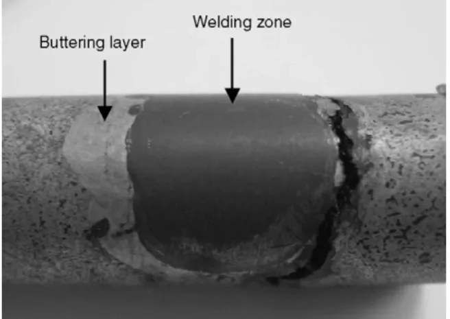
The welding samples consisted of bulk 400 mm × 160 mm × 120 mm parallelepiped blocks, representative of industrial SPF tools. A 20-mm deep V-groove (60◦) was machined on the two larger sides of the specimens, corresponding to a typical preparation prior to the weld-repair of a cracked component.
An automatic shielded metal arc welding (SMAW) process, allowing the control of both the welding rate and the arc volt-age, with a Lincoln PW 455 STT power source, was used for the filling with 2133Mn and 6222Mo, and for the buttering with Safonte. Buttering with Invar was carried out using a man-ual gas tungsten arc welding (GTAW) process, with a Kemppi Master 2850 power source, in DC electrode negative (DCEN) mode. The welding parameters, i.e. current, voltage and weld-ing rate were optimised for each couple base metal/filler metal (Table 3).
Prior to welding, the base metal samples were systemat-ically pre-heated uniformly at 400◦C using heat resistances, in order to reduce the thermal gradients and stresses dur-ing welddur-ing. A delay of 5–10 min was respected between two passes, in order to make the temperature field uniform after each pass. In this way, the interpass temperature is below 430◦C.
The weld-repair tests were done without buttering using the two filling materials, with a partial filling of the V-groove (10 or 16 passes), or a complete filling (40 passes). Except for the first three passes, where the arc tension was slightly higher, the same energy was used for all the weld passes of one assembly (Table 3). Weld-repair tests with prior buttering with Safonte or Invar, and a complete filling with 6222Mo were also carried out.
3.2. Microstructural investigations
Following welding, microstructural investigations were car-ried out on cross-sections of the welding specimens using a Philips XL30 scanning electron microscope (SEM) with an EDAX energy dispersive spectrometer (EDS). In order to quan-tify the extent of cracking for each welded sample, the total crack length was measured by image analysis (Aphelion soft-ware) from low magnification (30×) SEM micrographs taken over the whole cracked zone. Three cross-sections were anal-ysed for each welded sample.
Vickers (500 g) micro-hardness was also measured on the different zones of the cross-sections. Vickers micro-hardness profiles were obtained along lines crossing the base material–fusion zone interface, and if present the buttering layer, with a spacing of 100 !m. However, in order to maintain a 300 !m distance between two indents, to prevent the inter-action between the plastic zones of two neighbouring indents,
Table 3 – Summary of welding parameters
Filling material Buttering alloy Operation Current (A) Arc voltage (V) Welding speed (mm/s) Filler wire rate (mm/s) Number of weld passes Time between weld passes (min)
2133Mn None Filling 63 24–25 2.7 – 10 5–10
2133Mn None Filling 63 24–25 2.7 – 16 5–10
2133Mn None Filling 63 24–25 2.7 – 40 5–10
6222Mo None Filling 63 25–26 2.7 – 10 5–10
6222Mo None Filling 63 25–26 2.7 – 16 5–10
6222Mo None Filling 63 25–26 2.7 – 40 5–10
6222Mo Safonte Buttering 75 23–25 2.7 – 18 5–10
Filling 63 26 2.7 – 31 5–10
6222Mo Invar Buttering 110 12 1.6 4–5 22 5–10
the indents were made by “zigzagging” along the profile line.
3.3. Fatigue tests
The main objective of the fatigue tests performed in this study was to evaluate the effect of weld-repair on the in-service life-time of SPF tools, which are subject to thermal and mechanical cycles. In addition, some indications concerning the behaviour of the materials during welding, especially the propensity to cracking according to the type of filler material used, were also expected from these tests.
Previous works have shown that the main damage factor of SPF tools is related to the thermal cycling imposed to the dies (Baleix et al., 2001, 2002). A strain-controlled fatigue test was selected in order to simulate the mechanical strain result-ing from the thermal strain gradient due to thermal cycles. Strain-controlled fatigue is also convenient to investigate the behaviour of samples during multi-pass welding, each welding pass generating a rapid thermal cycle. The strain amplitudes were selected to be as representative as possible of a typical strain cycle of an industrial SPF operation (Baleix et al., 2001, 2002), which is in the same order of magnitude as the strain level induced by a welding pass. Three strain amplitudes, 0.4, 0.6 and 0.8%, resulting in a slight plastic strain at each cycle, were chosen.
Low-cycle fatigue tests were carried out using a 250 kN electro-hydraulic fatigue machine (MTS) and specimens were heated in a resistance furnace. The strain in the samples was controlled with a water-cooled 21-mm gauge length extensometer. Because of the high temperature achieved for specimen testing, special grips in Udimet 720 superalloy were used. Two test temperatures, typical of the SPF process, i.e. 750 and 920◦C, were selected. It is also in this temperature range that the mechanical resistance of the heat-resistant cast steels decreases somewhat. The strain rate was 10−4s−1for all tests. The fatigue specimens (150 mm length and 12 mm diame-ter) were machined from the welded blocks free of cracks, in order to obtain an unsymmetrical sample containing the weld-root (Fig. 1). In such a way, it is possible to observe structural effects due to the heterogeneous and unsymmetrical charac-teristics of a weld-repaired component. Two fatigue samples were prepared for each condition. Before machining, the weld-repaired blocks were annealed 20 h at 950◦C with slow heating and cooling rates (5◦C/min), to promote residual stress relief. This phenomenon of stress release is supposed to occur on SPF tools during their first in-service heating after weld-repair. In addition, this treatment prevents the samples from distorting during machining. Due to the great thermal stability of the base material, this annealing treatment has no effect on the grain size, but should have a slight effect on the precipitation and growth of secondary carbides (Branza, 2005).
Fig. 1 – Geometry of fatigue samples machined from weld-repaired blocks.
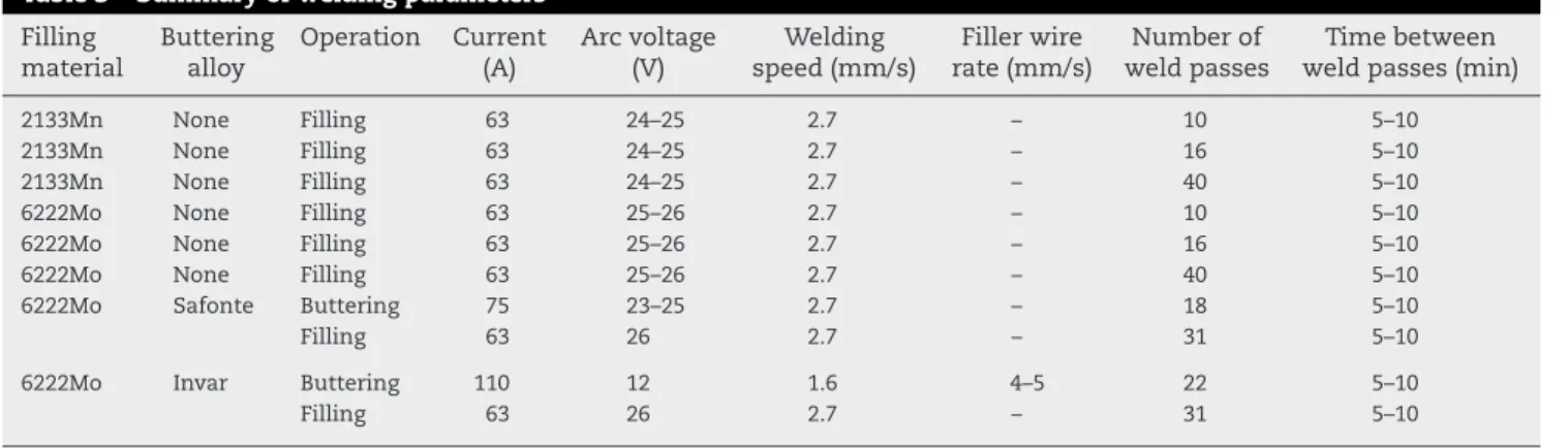
Fig. 2 – SEM micrographs of the base metal.
4.
Results of weld-repairs
4.1. Microstructural observations
SEM micrographs inFig. 2show the base material microstruc-ture. It is a typical dendritic structure (Fig. 2a), with coarse primary arms (about 200 !m width). EDS analysis reveals the presence of two different phases in the interdendritic regions (Fig. 2b), a major chromium-rich phase, in dark contrast, and a minor niobium-rich phase, in bright contrast. This indi-cates the formation of two types of primary carbides (possibly Cr23C6and Nb23C6 according to EDS analysis) at the end of the solidification, in the interdendritic regions. A fine precip-itation of secondary carbides is also observed in the dendrite core (Fig. 2).
When the number of passes is above or equal to 16, the cross-sections of weld-repaired samples without buttering reveal the presence of cracks in the base metal, close to the fusion zone.Fig. 3shows the evolution of the total crack length measured by image analysis versus the number of passes for the two different filling materials. The first cracks appear between the tenth and the sixteenth passes. Following this threshold, initial cracks tend to extend and/or new cracks initi-ate and propaginiti-ate until the filling of the V-groove is completed. This indicates a progressive increase of the maximum stress with the increase of the number of passes, which could reach the failure strength of the material, or a cyclic damage phe-nomenon induced by the successive heating and cooling, the 5–10-min delay between two passes allowing the cooling of
Fig. 3 – Effect of the type of filler metal and of the number of passes on the total crack length after welding.
the welded area. Note that cracking is much more important with the filling material 2133Mn, than with 6222Mo.
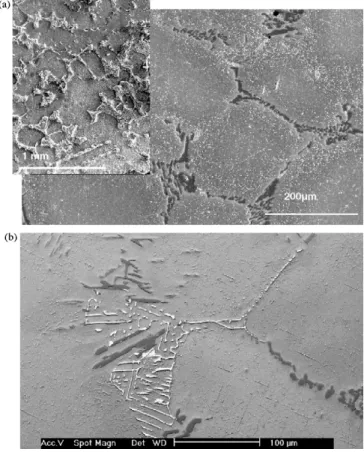
The cracks formed during welding are always located in the base metal, very close to the fusion zone (Fig. 4), and prop-agate across the carbide-rich interdendritic regions. On the other hand, prior buttering is shown to prevent weld-induced cracking completely (Fig. 5).
4.2. Micro-hardness tests
Fig. 6 shows the Vickers hardness profiles obtained over the cross-sections of weld-repaired samples, with or without buttering. The hardness profile in the base metal is widely scattered because of the heterogeneous microstructure of the cast steel, constituted of a quite soft austenitic matrix surrounded by interdendritic hard carbide-rich regions. The hardness of the welding zone for the two filling materials is higher than that of the base metal, suggesting an over-matching at room temperature. So this supposed higher yield strength of the filling materials at room temperature promotes the stress increase during cooling after welding and, as a con-sequence, the resulting cracking of the base metal. However, the difference in room temperature hardness between the base and the filling materials is not sufficient to explain the propensity to cracking satisfactorily, because the hardness of the welding zone with 6222Mo is higher than with 2133Mn, whereas the total crack length in the base material is lower with 6222Mo (Fig. 3). Note that due to the great thermal sta-bility of heat-resistant cast austenitic stainless steels, no heat affected zone (HAZ) is observed, so the hardness, as well as the microstructure, of the base material is not changed close to the fusion zone.
For the weld-repaired specimens achieved with buttering, the hardness of the buttering layer strongly depends on the buttering alloy. With Invar, the buttered layer hardness is slightly lower than the mean hardness of the base material, whereas with Safonte, hardness is higher than that of the filling zone (with 6222Mo). The beneficial effect of buttering with Invar is then attributed to the under-matching effect at room temperature. But in the case of Safonte, the strong over-matching observed at room temperature does not explain the
Fig. 4 – Macrograph of the cracked weld-repaired sample, after a complete filling with 6222Mo, without buttering (a), and crack path across the primary carbides within the base metal (b).
absence of cracks. However, due to the large temperature vari-ations and thermal gradients observed during welding, it is clear that the mechanical behaviour of the materials at high temperature should have a great impact on the stress increase in the base material. It is then important to obtain data con-cerning the high temperature behaviour of the materials.
4.3. Fatigue tests
Two types of result are expected from the low-cycle fatigue tests carried out on homogeneous fatigue samples (without weld) and on weld-repaired samples, with or without butter-ing. First, the number of cycles before failure is an indication on the lifetime of repaired components which can be com-pared to bulk material. Secondly, the comparison of the stress amplitudes, for a fixed strain range (supposed to correspond to mechanical strain resulting from a thermal gradient dur-ing SPF cycle or multi-pass welddur-ing), of welded and unwelded samples can assess the beneficial or detrimental effect of a filler material.
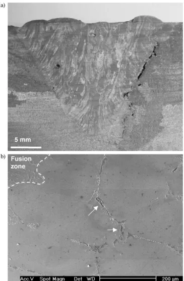
Fig. 5 – Macrograph (a) and micrograph (b) of a weld-repair sample, after a complete filling with 6222Mo and a prior buttering with Invar.
4.4. Cyclic behaviour of the base metal and of the
welded samples
At 750◦C, the stress amplitude (!"/2) for a fixed strain range (!ε) of the base material (without weld) increases during the first cycles, indicating a hardening effect. At 920◦C, stabilisa-tion is reached as soon as the first cycle is completed. However,
Fig. 6 – Vickers micro-hardness profiles in the various zones of the weld-repaired sample cross-sections.
Fig. 7 – Cyclic behaviour of the base metal and of the welded samples, for a strain amplitude of 0.4%.
Fig. 8 – Stabilised stress amplitude during fatigue tests for various strain amplitudes and temperatures for the base material and the welded samples.
wide scattering in stress range, reaching 20% for tests at 920◦C, is observed for samples tested in the same conditions. These differences are too important to be explained only by a cer-tain scattering of the test parameters, so it can be assumed that they are due to the large grain size of the base metal (Fig. 1), which makes the plastic behaviour of the samples very sensitive to the grain orientation.
Fig. 7compares the evolution of the stress amplitude dur-ing the first 10 cycles of a fatigue test, respectively performed on homogeneous (base material) and welded samples without buttering, for a maximum strain amplitude of 0.4%. For the same strain, the welded samples, either filled with 2133Mn or 6222Mo, sustain higher stress range than the homogeneous material. This trend is confirmed at 750◦C for all fatigue tests whatever the maximum imposed strain is (Fig. 8). In contrast, at 920◦C the stress range for a fixed strain is just slightly higher than in homogeneous base material, in samples welded with 6222Mo, whereas rather similar stress amplitudes are observed in samples welded with 2133Mn (Fig. 8). Note that at 750◦C, the stress is higher, for the same strain, with 2133Mn filler metal, whereas at 920◦C, the stress is higher with 6222Mo.
Fig. 9 compares the stress amplitude sustained at var-ious temperatures by the specimens without welding, the specimens welded with 6222Mo and the specimens welded following prior buttering with Invar. Despite the small number
Fig. 9 – Comparison of the stabilised stress amplitude during fatigue tests on the base material, the welded samples with 6222Mo, and the welded samples with prior buttering with Invar.
Fig. 10 – Localisation of the fracture during fatigue tests of the buttered samples.
of fatigue tests carried out on samples welded with buttering (only three fatigue test conditions, with two samples per con-dition), it seems that buttering has no significant effect on the material behaviour.
4.5. Fatigue lifetime and localisation of the fracture
If the behaviour of the buttered and non-buttered samples during the first 10 cycles is rather similar, the localisation of fracture shows some significant differences. When the sam-ples are not buttered, fracture generally occurs in the base metal, close to the fusion zone (Fig. 4), or in some cases in the centre of the sample, according to a specific path cross-ing the base metal and the fusion zone. In this last case, the fracture surface is only oxidised in the part crossing the base metal, which indicates that the crack initiates and progres-sively propagates within the base metal, the final catastrophic failure occurring in the fusion zone. In the samples buttered prior to welding, fracture takes place in the buttering layer after a low number of cycles (Fig. 10).
Fig. 11indicates the average number of cycles before failure of both the bulk material and the various welded samples. The
bulk material shows a typical behaviour, the number of cycles before failure decreasing with the strain range. The welded materials show a much more complex behaviour: in most con-ditions, the number of cycles before failure increases with the strain range. This could be due to damage to the base mate-rial during welding, such as microcracking, which has not been detected by the microstructural analysis. The weld-repair with prior buttering with Invar does not show any significant differ-ence with weld-repair without buttering at 750◦C. In contrast, it decreases drastically the number of cycles before failure at 920◦C. Note that only two fatigue samples were tested for each condition, which could explain the non-standard fatigue life behaviour observed on welded samples. Indeed, the possible presence of undetected microcracks in the samples induces wide lifetime scattering, which requires a more relevant sta-tistical analysis, and then many more samples.
5.
Discussion
5.1. Fatigue lifetime of weld-repaired components
The weld-repaired samples always exhibit a lower fatigue life-time than the bulk non-welded material, both at 750 and 920◦C (Fig. 11). Consequently, it may be concluded that the sole verification of the absence of cracking over the investigated specimen, which is ensured by the deposition of a buttered layer prior to welding, does not guarantee acceptable fatigue strength.
In order to understand the failure mechanism during fatigue loading in heterogeneous welded samples better, a numerical simulation of strain-controlled fatigue test is per-formed using Abaqus software (Branza, 2005).Fig. 12shows the typical stress distributions calculated in a welded sample, for a fixed strain range. The maximum stresses occur in the fusion zone. In addition, note that there is also, due to the mis-matching effect, some stress concentration in the base metal, close to the interface with the welding zone and at the oppo-site side of the fusion zone. These regions strictly correspond to the zones where failure occurs in the samples.
However, the stress concentration due to the mis-matching between the welding zone and the base material (stiffness
Fig. 11 – Comparison of the number of cycles to failure for the various fatigue tests.
Fig. 12 – Axial stress field (in MPa) during fatigue test calculated by numerical simulation.
and yield strength differences) is not the only factor respon-sible for the strong decrease of the number of cycles before failure experimentally measured.Figs. 7 and 8show that, for the same strain, the stress amplitude is higher in the welded samples than in the bulk samples.Fig. 13shows master S–N W ¨ohler curves at 750 and 920◦C, plotting the stress amplitude versus the number of cycles to failure, including all experi-mental results obtained for bulk and welded materials. Note that the continuity between the data characteristic of the bulk and the welded material is rather good. This indicates that the high stress imposed on the welded specimens during strain-controlled fatigue loading could justify the lower number of cycles before failure assessed experimentally.
So the main detrimental effect resulting from welding is to enhance the stiffness of the samples, or of the structural parts in the case of industrial applications, which increases the stress amplitude when the material is subject to a fixed strain (induced by a thermal gradient for instance). A sec-ondary effect is the generation of stress concentration due to the mis-matching between the welding zone and the base metal, which determines the location of fracture.
In the samples weld-repaired with prior buttering, the number of cycles before failure decreases compared to bulk
Fig. 13 – S–N W ¨ohler curves showing the stabilised stress amplitude vs. the number of cycles to failure when the failure occurs in the base metal.
Fig. 14 – Evolution of the stress amplitude during fatigue tests of the samples welded with 6222Mo, with or without buttering with Invar.
samples or classically welded samples. In this case, the fail-ure is systematically located in the buttering layer. However, for a given strain, the stress amplitude during the first cycles is in the same order of magnitude as that obtained for stan-dard welding (Fig. 9). For the buttered specimens, a decrease of the stress amplitude is measured on the stress–strain loops after few cycles. This indicates a softening or more probably a damaging of the buttering layer, which in turn provokes its early cracking (Fig. 14). These results are in agreement with previous works, reporting the lower toughness of a soft-ened HAZ confined between two harder zones (base metal and even-matching or over-matching welding zone) (Angamuthu et al., 1999). This behaviour may result from an increase in the stress tri-axiality as the thickness of the soft layer decreases, thus preventing its plastic strain. This enhances the risk of cracking of this layer, in spite of the high ductility of the material (Kim and Schwalbe, 2004). This also explains satis-factorily the establishment of stresses with similar amplitude, for a given strain, observed with or without buttering. In addi-tion, the presence of a soft welding zone (under-matching) increases the crack-tip plastic deformation in this region and then favours the propagation of cracks (Kim and Schwalbe, 2004).
5.2. Weld-cracking
The mechanism of cracking of the base metal during welding is a typical solid-state cracking phenomenon due to the low ductility of the material. The propensity to cracking of the base metal depends on the stress level in this material. The two filling metals used show higher yield strength than the base material (over-matching), so they both promote the crack-ing of the base metal in isothermal conditions, as confirmed by isothermal fatigue test results. However, the problem is more complex during welding, because the strains and the temperatures are not uniform in the material. The filler mate-rial, which is deposited into the welding arc, is subject to a higher temperature than the base metal during its deposit and its cooling. The yield strength being lower when the tem-perature is higher, the difference between base metal and filler metal yield strength is then reduced. Consequently, the real over-matching effect during welding is lower than the
Fig. 15 – Yield strength vs. temperature for the base and filling materials.
over-matching in isothermal conditions. In addition, the non-uniform thermal strain established during welding creates a complex stress field compared to the uni-axial and isothermal fatigue loading.
Despite these differences, it has been shown in a previ-ous work that for a given over-matching, the higher residual stresses after welding occur in the fusion zone and in the base metal close to the interface, in the region where the thermal gradient is the highest (Branza et al., 2004b, 2005) and where the cracks are experimentally observed in the welded sam-ples without buttering. This unambiguously shows that the over-matching effect persists in welding conditions without buttering, with the filling materials used, despite the thermal gradient, so that the fatigue-cracking and the weld-cracking mechanisms are rather similar.
The similarities persist when the effect of both filling mate-rials is compared. Alloy 2133Mn, which has the lower yield strength up to 900◦C (Fig. 15), produces a higher stress ampli-tude during strain-controlled fatigue tests of welded samples at 750◦C than alloy 6222Mo (Fig. 8). This could be due to an enhanced hardening effect in alloy 2133Mn, which is in agree-ment with the higher crack length observed after welding with this filling metal (Fig. 3).
Buttering samples prior to welding prevents weld-cracking, indicating a significant effect of the buttering on the magni-tude of the stress field in the base material developed upon welding.
However, fatigue tests at 750 and 920◦C show a similar stress amplitude for fatigue specimens either prepared with or without buttering, which is due to the stress tri-axiality in the thin buttering layer confined between two harder regions. The effects of the isothermal fatigue loading and the thermo-mechanical cycles due to a multi-pass welding on the failure mechanisms of buttered samples are rather different. This could have two main reasons. First, the thermal gra-dient during welding lowers the mis-matching between the base material, the buttering alloy and the filling metal, as previously discussed. Secondly, the geometry as well as the loading are very different during fatigue test and multi-pass welding. In this last case, the geometry of the specimen pro-gressively changes with the filling of the V-groove, whereas the induced mechanical loading is non-uniform and more “localised” (around the deposited pass). Then, we can assume the stress tri-axiality in the buttering zone during welding is
lower than during a fatigue test. This allows the plastic flow of the buttering alloy and a beneficial release of the stress in the base metal.
6.
Conclusion
The multi-pass weld-repair of a heat-resistant cast steel used for the manufacturing of SPF dies was carried out with two filler materials, with or without prior buttering of the base material surface. The non-buttered samples systematically crack after the tenth filling pass whereas the buttered sam-ples remain free of cracks up to the deposition of the final fortieth pass. The strain-controlled fatigue lifetime of the heat-resistant cast steel is strongly reduced by the presence of a welding zone as a result of an increase of the stress ampli-tude due to the over-matching effect and to the presence of stress concentrations in the base material close to the inter-face with the welding zone.
In the case of the buttered samples (with Invar), the fatigue lifetime drastically decreases because of the occurrence of a tri-axial stress which inhibits the plastic strain of the soft but-tering layer and enhances its cracking.
As a consequence, it is concluded that if the buttering tech-nique efficiently prevents weld-cracking, it strongly limits the fatigue lifetime of the components.
r e f e r e n c e s
Anand, D., Chen, D.L., Bhole, S.D., Andreychuk, P., Boudreau, G., 2006. Fatigue behaviour of tailor (laser)-welded blanks for automotive applications. Mater. Sci. Eng. A 420, 199–207. Angamuthu, K., Guha, B., Achar, D.R.G., 1999. Investigation of
dynamic fracture toughness (JId) behaviour of strength mis-matched Q & T steel weldments using instrumented Charpy impact testing. Eng. Fract. Mech. 64, 417–432. Baleix, S., Le Roux, S., Bernhart, G., Lours, P., 2001. Surface and
image analysis of oxides grown and spalled on heat resistant cast steels exposed to thermal cycles. J. Mater. Process. Technol. 118, 321–328.
Baleix, S., Bernhart, G., Lours, P., 2002. Oxidation and oxide spallation of heat resistant cast steels for superplastic forming dies. Mater. Sci. Eng. A 327, 155–166.
Bhaumik, S.K., Rangaraju, R., Parameswara, M.A., Bhaskaran, T.A., Venkataswamy, M.A., Raghuram, A.C., Krishnan, R.V., 2002. Failure of reformer tube of an ammonia plant. Eng. Fail. Anal. 9, 553–561.
Bohler Thyssen Welding, 2005. Welding guide.
Boronski, D., 2006. Cyclic material properties distribution in laser-welded joints. Int. J. Fatigue 28, 346–354.
Borrego, L.P., Pires, J.T.B., Costa, J.M., Ferreira, J.M., 2007. Fatigue behaviour of laser repairing welded joints. Eng. Fail. Anal. 14, 1586–1593.
Branza, T., 2005. Ph.D. Thesis. universit ´e Toulouse III, France. Branza, T., Martinier, A., Duchosal, A., Deschaux-Beaume, F.,
Bernhart, G., Lours, P., 2004a. Fatigue damage and weld repair of heat-resistant cast steel SPF dies. In: Proceedings of the Third European Conference on Super Plastic Forming. C ´epadues-Editions, Albi, France, pp. 133–138.
Branza, T., Duchosal, A., Fras, G., Deschaux-Beaume, F., Lours, P., 2004b. Experimental and numerical investigation of the weld repair of superplastic forming dies. J. Mater. Process. Technol. 155–156, 1673–1680.
Branza, T., Duchosal, A., Bordreuil, C., Deschaux-Beaume, F., Fras, G., Lours, P., 2005. Influence of the welding processing on weld repair quality of SPF tools. In: Proceedings of the Fourth European Conference on Superplastic Forming. IOM Communications, Manchester, UK, pp. 121–126.
Chellapandi, P., Chetal, S.C., 2000. Influence of mis-match of weld and base material creep properties on elevated temperature design of pressure vessels and piping. Nucl. Eng. Des. 195, 189–196.
Colwell, R.L., Hoffman, J.J., 1998. Weld cracking in modified heat-resistant castings, a microstructural investigation. In: Proceedings of the NACE International Annual Conference Corrosion 98. NACE International (paper 423).
De Almeida, L.H., Ribeiro, A.F., Le May, I., 2003. Microstructural characterization of modified 25Cr–35Ni centrifugally cast steel furnaces tubes. Mater. Charact. 49, 219–229.
Ebert, H.W., November 1976. Fabrication of HK-40 in the field. Weld. J., 939–945.
Haro, S., Lopez, D., Velasco, A., Viramontes, R., 2000.
Microstructural factors that determine the weldability of a high Cr-high Si HK 40 alloy. Mater. Chem. Phys. 66, 90–96. Haro, S., Colas, R., Velasco, A., Lopez, D., 2002. Study of
weldability of a Cr–Si modify heat-resistant alloy. Mater. Chem. Phys. 776, 831–835.
Haro, S., Ramirez, C., Mendoza, E., Rodriguez, J., Colas, R., 2003. Microstructural analysis of heat-resistant welded pipes. Mater. Charact. 51, 21–27.
Kim, Y.J., Schwalbe, K.H., 2004. Numerical analyses of strength mis-match effect on local stresses for ideally plastic materials. Eng. Fract. Mech. 71, 1177–1199.
Montagnon, J., Moraux, J.Y., Hocquette, A., 2004. Application of thermo-calc to the developments of new heat-resistant alloy casting for specifics SPF-DB tooling. In: Proceedings of the Third European Conference on Super Plastic Forming. C ´epadues-Editions, Albi, France, pp. 117–124.
Ravi, S., Balasubramanian, V., Babu, S., Nemat Nasser, S., 2004a. Assessment of some factors influencing the fatigue life of strength mis-matched HSLA steel weldments. Mater. Des. 25, 125–135.
Ravi, S., Balasubramanian, V., Nemat Nasser, S., 2004b. Effect of mis-match ratio (MMR) on fatigue crack growth behaviour of HSLA steel welds. Eng. Fail. Anal. 11, 413–428.
Ravi, S., Balasubramanian, V., Babu, S., Nemat Nasser, S., 2004c. Influences of MMR, PWHT and notch location on fatigue life of HSLA steel welds. Eng. Fail. Anal. 11, 619–634.
Ravi, S., Balasubramanian, V., Nemat Nasser, S., 2005. Influences of post weld heat treatment on fatigue life prediction of strength mis-matched HSLA steel welds. Int. J. Fatigue 27, 547–553.
Ravi, S., Balasubramanian, V., Nemat Nasser, S., 2006. Fatigue life prediction of strength mis-matched high strength low alloy steel welds. Mater. Des. 27, 278–286.
Ray, A.K., Sinha, S.K., Tiwari, Y.N., Swaminathan, J., Das, G., Chaudhuri, S., 2003. Analysis of failed reformer tubes. Eng. Fail. Anal. 10, 351–362.
Saxena, A., 2007. Role of nonlinear fracture mechanics in assessing fracture and crack growth in welds. Eng. Fract. Mech. 74, 821–838.
Vojvodic Tuma, J., Sedmak, A., 2004. Analysis of the unstable fracture behaviour of a high strength low alloy steel weldment. Eng. Fract. Mech. 71, 1435–1451.
Wu, X.Q., Jing, H.M., Zheng, Y.G., Yao, Z.M., Ke, W., Hu, Z.Q., 2000. The eutectic carbides and creep ruptures strength of 25Cr20Ni heat-resistant steel tubes centrifugally cast with different solidification conditions. Mater. Sci. Eng. A293, 252– 260.
Zhang, H., Zhang, Y., Li, L., Ma, X., 2002. Influence of weld mis-matching on fatigue crack growth behaviors of electron beam welded joints. Mater. Sci. Eng. A334, 141–