HAL Id: hal-00630259
https://hal.archives-ouvertes.fr/hal-00630259
Submitted on 7 Oct 2011
HAL is a multi-disciplinary open access archive for the deposit and dissemination of sci-entific research documents, whether they are pub-lished or not. The documents may come from teaching and research institutions in France or abroad, or from public or private research centers.
L’archive ouverte pluridisciplinaire HAL, est destinée au dépôt et à la diffusion de documents scientifiques de niveau recherche, publiés ou non, émanant des établissements d’enseignement et de recherche français ou étrangers, des laboratoires publics ou privés.
Peer-to-Peer framework for RFID/non-RFID
reader-enabled users
Oscar Botero, Hakima Chaouchi
To cite this version:
Oscar Botero, Hakima Chaouchi. Peer-to-Peer framework for RFID/non-RFID reader-enabled users. Green Computing and Communications (GreenCom), 2010 IEEE/ACM Int’l Conference on & Int’l Conference on Cyber, Physical and Social Computing (CPSCom), 2010, pp.10.1109/GreenCom-CPSCom.2010.20. �hal-00630259�
Peer-to-Peer framework for
RFID/non-RFID reader-enabled users
Oscar Botero and Hakima Chaouchi
CNRS SAMOVAR, UMR 5157. Telecom SudParis, Evry, France {oscar.botero, hakima.chaouchi}@it-sudparis.eu
Abstract— Radio Frequency Identification (RFID) technology can be used for a wide range of applications such as tracking and tracing objects and individuals, localization, collaborative platforms and the like. For portable devices with non-RFID capabilities there is no possibility to allow them to benefit from this technology if no integration platforms are implemented. In this paper we propose an P2P-based architectural framework in order to enable RFID applications for devices that have non-RFID reading capabilities but a wireless interface. We also propose an application layer time-division-based scheme to allow RFID-enabled devices to scan for RFID tags, preventing reader-to-reader interference and avoiding reading collisions. We depict the system architecture and we perform simulations to compare transmission delay metrics and numerical results are provided.
Keywords- Peer-to-peer; Radio Frequency Identification; RFID reading proxy; WLAN
I. INTRODUCTION
Radio Frequency Identification (RFID) systems are becoming more popular due to reduced components costs [1] but also because of their versatility. Among the myriad of RFID applications we can find [2]: identification and tracking of objects and individuals, localization, citizen’s documents (passports, driving licenses), collaborative architectures, public transport access. RFID is also a key technology for the Internet of Things. These systems are composed of readers, tags and middleware. Basically the tags provide an identification number linked to persons, animals or items that is retrieved by readers and processed by the middleware.
If we consider current portable devices like mobile phones, laptops, pads, etc we observe a lack of RFID embedded hardware implying that is not feasible for them to interact with such systems; however, we can suggest a network architecture that allows integration of non-RFID enabled but wireless-interface-enabled devices and provide RFID-based applications to them. In this paper we propose a Peer-to-Peer (P2P)-based RFID architecture for users with non-RFID capabilities in order to allow them to take advantages of this technology.
Peer to peer architectures are flexible solutions when computational resources and data sharing are involved. The nodes in such approaches can perform as clients or servers depending on the tasks required. The advantage of P2P against classical client-server approaches lies in the distributed deployment of the services as well as the scalability, flexibility and fault-tolerance of the network.
For this work we based our analysis on IEEE 802.11. These are the most popular short-distance wireless transport protocols [3] that allow us to implement affordable, flexible and scalable
communication platforms although other wireless technologies can be used to establish the network backbone.
Based on previous research [4] we integrated a proxy-based security solution to perform network management and AAA functions over a P2P overlay.
Regarding the RFID reader-to-reader interference different anti-collision protocols have been proposed [5, 6, 7, and 8]. In our work we suggest a time-division-based scheduling mechanism allowing RFID readers to operate in a sequenced manner and more precisely permitting heterogeneous readers (using different lower layers protocols and either sharing or not the same RFID operation frequency) to be part of the network. The mechanism is controlled by P2P overlay messages.
We used NS2 to simulate the data exchange between nodes and obtain the associated transmission delay. We evaluated the case of 20 simultaneous nodes being served.
For this work we rely on the following assumptions: • Readers use the EPC global Generation-2(Gen2)
protocol to scan tag’s IDs.
• We consider RFID passive tags to be deployed not changing their position frequently.
• Tags’ antenna is never at 90° with respect to the reader thus tags can be always detected.
• All the nodes have a wireless interface and can run the P2P protocols required.
The rest of the paper is structured as following. In section II the related work is mentioned. In section III we describe the system architecture. In section IV the anti-collision mechanism is depicted. In section V we present the system delay analysis. In section VI an application example is shown and finally we conclude the paper in section VII.
II. RELATED WORK
P2P-RFID collaborative networks have been proposed in previous research work. In [8] a P2P scheme to deal with the reader-to-reader collision problem is presented. In [9] a P2P Collaborative RFID Data Cleaning Model is described. A P2P data resolver is implemented in [10]. We observed also research on 802.11 and RFID integration in [3] for localization services. In [11] an architectural RFID system for localization is described. It presents a framework based in edge and intermediate nodes, in a distributed manner. In these papers we could not find neither how to integrate users with non-FID capabilities nor heterogeneous readers to a RFID network.
The novelties we suggest are three: First, the integration of non-RFID devices in the RFID network via the P2P framework to benefit from available information related to the surrounding RFID tags and providing all the nodes in the system with an extended virtual range. This virtual reading range allows users to obtain information from RFID network deployments overcoming physical tags’ scanning limitations. Second, the prevention of reader-to-reader interference by a time-division-based mechanism that allows the inclusion of heterogeneous mobile readers, and third, our Service Authentication Proxy already developed is proposed to be part of the platform. This proxy node runs over a P2P framework and performs authentication of all joining nodes among other features. The next section of this paper will describe the System Architecture depicting all the entities and features.
III. SYSTEM'S ARCHITECTURE
A. Network Architecture
The proposed Framework allows portable devices to obtain RFID tags’ IDs by using a P2P overlay. Basically there are RFID proxies that will manage the requests that come from both non-RFID-enabled users and mobile readers, providing them with the requested information. The system also offers: service authentication, AAA functions (authentication, authorization, and accounting), and reader-to-reader interference control. Our approach presents a generic platform that can be set up to satisfy different kind of requirements. It consists of the following elements: Multi-Mode-Nodes (MMN), Mobile Readers (MR), users with non-RFID capabilities or Virtual Readers Nodes (VRN), Management and Authenticator Nodes (MAN) and passive RFID tags (Fig. 1). These components are described as follows:
Fig. 1. Network architecture.
B. MMN 1) Definition
A Multi-Mode-Node (MMN) is the integration of a wireless (e.g. Wi-Fi) and RFID interfaces bind to a processing module. It is basically a RFID proxy that manages users’ requests related to the RFID reading service.
2) Operation
At startup the MMN will perform a security control process against the MAN in order to be authenticated, then a setup stage will allow it to be configured obtaining the applications and settings required to operate. Later the MMN will be ready to manage users’ requests. A user’s incoming request can be of three kinds: authorization, scanning (RFID reading) and time slot assignation. The MMN will forward the authentication request to the MAN performing the security control to access
the network. At this step the user can also obtain the applications and settings required in the network. The scanning process can be triggered by the user, the MAN and the MMN itself and once the tags list is obtained it will be propagated into the network via the P2P overlay (Share process). The RFID reader-to-reader interference is controlled by using a time-division scheduling mechanism. The MMN will scan its environment for RFID tags’ IDs on a time slot basis. These time slots will be defined at the Setup step. Each MMN will obtain from the MAN a group of time slots in which the node will be able to scan for tags and also to assign them to requesting users. The basic processes of a MMN are presented in the next figure (Fig. 2).
Fig. 2. Multi-Mode-Node processes.
C. MAN 1) Definition
The Management and Authenticator node (MAN) provides service access control, AAA, and network management features (statistics, network state, etc). A MAN is based on a proxy solution with a distributed AAA server. We developed a practical implementation on Java SE by using a set of P2P protocols developed by Sun [3, 12, 13, 14, and 15] and we included encryption and MAC (Message authentication code) in the message information exchange to secure the communications.
2) Operation
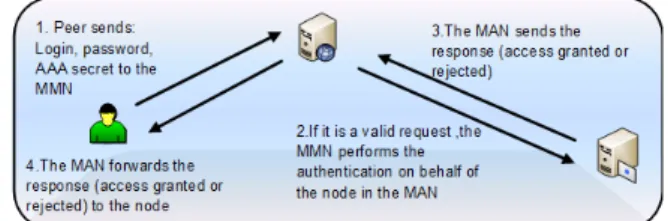
The MAN’s authentication mechanism is depicted in Fig. 3. It behaves as a proxy that communicates with the AAA server on behalf of the peer in order to authenticate the user. This node will grant that only authorized users will join and use the network services.
Fig. 3. Management and authenticator Node (MAN).
D. VRN 1) Definition
Virtual Reader Nodes (VRN) are portable devices (i.e. mobile phones, laptops, pads, and so on) with non-RFID capabilities but with a wireless interface. They will obtain tags’ IDs through a transferred list from the MMN by using the network overlay. The virtual range is defined as a feature that allows the node to obtain RFID IDs present in the system gathered in a collaborative way among all the nodes and
consequently overcoming physical range scanning limitations. By exchanging the discovered tags’ IDs the network will build a database representing the RFID deployment.
2) Operation
The basic operation chart flow of VRNs is shown in the next figure (Fig. 4). The VRN will perform a security control in order to be authenticated. The MMN and the MAN will be responsible to provide or deny the access to the overlay. At this step the VRN can also obtain the applications and settings required to operate. Then the VRN will obtain through the wireless interface the list of scanned tags. The user will have three more choices: to share this information with other authenticated nodes, to request again for tags’ IDs or to disconnect from the network.
Fig. 4. Virtual Reader Node (VRN) operation chart flow.
E. MRN 1) Definition
Mobile readers are devices that have RFID scanning capabilities. They can be homogeneous or heterogeneous regarding the technology and operation frequency.
2) Operation
MRN follows the same principle that VRN differing only on the scheduling and time slot assigned to scan RFID tags’ IDs.
If a MR requires tags’ scanning, it will be synchronized with the MMN in order to obtain a valid time slot that will be used to obtain the tags’ IDs. The MAN will assign a group of time slots to each MMN and they can be increased or reduced related to the network capacity and service delay.
IV. ANTI-COLLISION MECHANISM
We suggest a time-division-based mechanism to prevent the interference of the MMNs while scanning RFID tags’ IDs. MMNs will perform a sequenced scanning coordinated by the MAN. MAN will provide to each MMN a set of time slots available that will be used for the node itself and the MRNs that request reading slots. On this way it is also possible to integrate heterogeneous readers into the network because it is a technology-independent mechanism.
Only non-interfering readers are allowed to scan tags but if a node is far enough not to cause interference to a MMN, or if a mobile node located in the MMN’s cell which scanning power is low in relation to the MMN’s then it is possible to allow it to read tags simultaneously. Network planning should be performed in order to define the interfering zones and also each device should have a profile description to let the system know its power capabilities.
The mechanism works in this way: the system will schedule the RFID tags’ scanning process following a time slot division scheme. The MAN will assign to each registered MMN a pull of time slots that will allow them to schedule a certain number
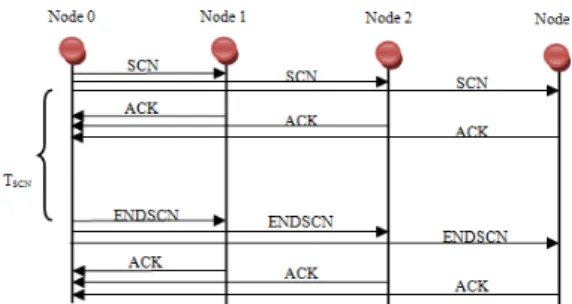
of mobile readers in each MMN cell. This process can be run dynamically to extend or reduce the number of assigned time slots based on performance metrics. The MMN will coordinate the scanning by using two messages in the network overlay: SCN and ENDSCN. SCN will notify that the node is reading tags’ IDs. Once it is finished it will send an ENDSCN message to inform that the node ended the process. TSCN is the time needed for the node to obtain all the tags’ IDs located on the readers’ range. Each node will reply to these messages with an ACK. If the nodes will not interfere due to distant location, the message will not be propagated to them and they can perform parallel scanning. This will be determined based on the network planning. The message exchange for 4 nodes (MMN/MRN) is shown in the following figure (Fig. 5)
Fig. 5. Overlay Messages for anti-collision mechanism
If there is an increasing number of MRNs requesting for time slots, the Service Delay will increase depending on variables like power, number of tags to read, tag identification speed among others. On the other hand the mechanism prevents the interference because only one reader will be scanning at a time.
V. FRAMEWORK DELAY ANALYSIS
A. Simulation Setup
We set up a simple NS2 scenario based on 802.11g in order to evaluate the transmission delay of the MMNs. We used the Two-ray ground reflection model and a frequency operation of 2.4 GHz on Direct Sequence Spread Spectrum (DSSS). It was set by a 30x30 meters flat grid and we defined three configurations:
• A MMN in the middle of the grid and a single fixed user node at (0, 0).
• A MMN in the middle of the grid and a single user node at the (0, 0) location performing random movements.
• A MMN in the middle of the grid and 20 user nodes at random fixed positions inside the grid.
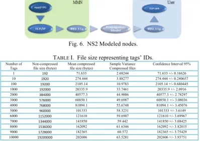
The nodes were modeled following the scheme depicted in Fig. 6. In order to measure the transmission delay we created a list of tags’ IDs to be sent. We obtained the file size associated to a specific number of tags. We computed random files (by using a bash shell script) with unique tags’ IDs with 96 bits extension as the EPC standard stands [16]. These files were transmitted from a modeled MMN to a user node and the data rate of the channel varied in these steps: 1, 6, 18, 36, and 54 Mbps. We
performed the evaluation of the transmission of gzip compressed files and we measured the associated delay. In the following table (Table I) we present the mean values for compressed and non-compressed files that represent the list of scanned tags to be transmitted from the MMNs to the users.
Fig. 6. NS2 Modeled nodes. TABLE I. File size representing tags’ IDs.
Number of Tags
Non-compressed file size (bytes)
Mean compressed file size (bytes)
Sample Variance Compressed files Confidence Interval 95% 1 192 71.633 2.68244 71.633 +/- 0.16626 10 1920 274.444 3.88277 274.444 +/- 0.240657 100 19200 2105.14 10.9783 2105.14 +/- 0.680445 1000 192000 20335.9 33.7461 20335.9 +/- 2.0916 2000 384000 40577.3 44.9006 40577.3 +/- 2.78297 3000 576000 60850.1 49.6987 60850.1 +/- 3.08036 4000 768000 81094.1 55.6748 81094.1 +/- 3.45076 5000 960000 101333 58.3231 101333 +/- 3.6149 6000 1152000 121610 59.6907 121610 +/- 3.69967 7000 1344000 141850 59.442 141850 +/- 3.68425 8000 1536000 162092 61.6346 162092 +/- 3.82015 9000 1728000 182365 60.572 182365 +/- 3.75429 10000 19200000 202606 63.5281 202606 +/- 3.93751
B. RFID Tag Identification Speed (TIS)
Based on the results obtained in [17, 18, and 19] we considered the EPC- Gen2 protocol to calculate the TIS. For a data rate of 62.5 Kbytes between tags and readers we obtain a constant rate of approximately 280 tags per second. In Fig. 7 we observe the time required to detect n tags (from 0 to 10k tags).
Fig. 7. Tag identification delay for Gen2 protocol based on 280 tags/second.
C. Transmission Delay
In the first simulation case (A MMN in the middle of the grid and a single fixed user node at (0, 0)) we obtained the results shown in Fig. 8. We observe the transmission delay of the different gzip compressed files (tags’ IDs) for different data rates. For the highest data rate (54 Mbps) the transmission delay for a file representing 10k tags (202,606 Kbytes) is about 1.33 seconds contrasted with 3.24 seconds for 1 Mbps data rate. From 0 to 100 tags the delay remains almost the same for all data rates (about 1.12 to 1. 32 seconds) and then increases linearly.
Considering the second simulation case (A MMN in the middle of the grid and a single user node at the (0, 0) location performing random movements) the plot is presented in the Fig. 9. We observe that the delay increases slightly compared
to the fixed node due to the node’s movements and the power variations. For a 54 Mbps data rate and 10k tags the delay is approximately 1.84 seconds. For 1 Mbps we obtained 3.74 seconds.
Fig. 8. File transmission delay representing tags’ Ids from a MMN to a fixed VRN.
Fig. 9. File transmission delay representing tags’ IDs from a MMN to a random moving VRN.
For the third simulation case, we placed 20 user nodes and we transmit the tag’s files in parallel. In the following figure we present the delay experienced (Fig. 10).
Fig. 10. Parallel File transmission delay representing tags’ IDs from a MMN to 20 fixed users.
From 0 to 100 tags, the transmission delay remains almost constant for all the different data rates evaluated (1.9 seconds). For a 10k tags’ list, we obtain a delay of 9.27 seconds for 54Mbps and 45.37 seconds at 1Mbps data rate.
D. User Service Delay
The first time a node will be served it will experience a Service Delay (USD) based on the following parameters (1)
User Service Delay = TAuth + TSetup + TReq + TscnDelay + TTx (1) Where:
• TAuth = Delay of node authorization
• TSetup = Time to download required applications and configuration
• TReq = Time to send a request to the MMN • TscnDelay = MMN scanning delay
• TTx = Tags’ Ids transmission delay
For the following requests the Service Delay is reduced to (2) USD = TReq + TscnDelay + TTx (2) If the MMN had scanned its environment before a user request the USD will be (3)
USD = TReq + TTx (3) To estimate a rough value for USD we can assume:
• TSetup = TTx ≈ 2 s that represents the time to download a file of 200 k bytes @ 54 MBps for a fixed node. This value will increase depending on the size of the application to be downloaded.
• TReq and TAuth are in the milliseconds order (60 ms), as we obtained in [4] thus we can neglect them (not significant compared with seconds order).
• TscnDelay = 35 s (10K tags using Gen2 protocol) Thus, USD = 37 s for a single fixed node served at 54Mbps data rate obtaining a list of 10k tags. If we assume that the MMN had already read the tags and has the list prepared by the time the request was made then: USD ≈ 2 s.
For 20 nodes we can obtain: USD = 35 s + 20 x 2 s = 75 s at 54Mbps data rate obtaining a list of 10k tags. We observe that the USD will increase linearly with the number of requesting nodes.
VI. EXAMPLE APPLICATION
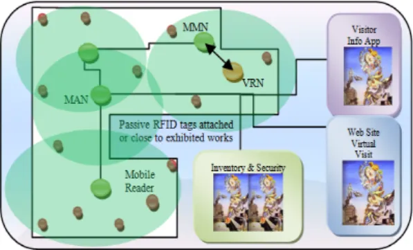
Suppose a scenario inside a museum. Instead of simple audio guides, users can use their Wi-Fi enabled mobile phones to download the Museum’s guide application. The system will also automatically keep track of the works in exhibition by using RFID passive tags attached or close to them. Readers can be activated to perform surveillance tasks as well. By obtaining the tags’ list with the associated information description, the museum can publish exhibition’s websites and keep an inventory database (see Fig. 11).
Fig. 11. Museum Application.
VII. CONCLUSION AND FUTURE WORK
This paper describes a P2P-RFID-WiFi framework that allows non-RFID-reader enabled devices to take advantages of RFID network deployments. We provide a virtual reading range to both non-enabled RFID devices and mobile readers. We also suggested an application layer time-division-based scheduling mechanism to allow RFID readers to scan for tags in a sequenced way and to integrate heterogeneous readers to the network. We plan to implement the framework and to set up a testbed to obtain real platform’s performance metrics.
REFERENCES
[1] ODIN Technologies, RFID tag pricing guide. May 2009. http://www.odintechnologies.com
[2] Wiebking L., Metz G., Korpela M., Nikkanen M, Penttila K., A Roadmap for RFID Applications and Technologies, Published on Internet by "Coordinating European Efforts for Promoting the European RFID Value Chain" (CE RFID). August 12, 2008. http://www.rfid-in-action.eu/public/results
[3] B. Ding, L. Chen, D. Chen, H. Yuan. Application of RTLS in Warehouse Management Based on RFID and Wi-Fi, Wireless Communications, Networking and Mobile Computing, 2008. WiCOM '08.
[4] O. Botero, H. Chaouchi. Platform and experimentation of secure service location with P2P/Client-Server over ad hoc networks. IFIP Wireless Days Paris December 15-17 2009.
[5] K. Finkenzeller. RFID handbook - Second Edition. JOHN WILEYSONS, 195–219, 2003.
[6] Engels Daniel W. The reader collision problem, AUTO-ID Center White paper, http://autoid.mit.edu/whitepapers/MIT-AUTOID-WH-007.PDF, 2002
[7] Engels, D.W., S.E. Sarma, The reader collision problem, IEEE International Conference on Systems, Man and Cybernetics, Hammamet, Tunisia, Oct. 2002, pp.
[8] S. Zhou, Z. Luo, E. Wong, C.J. Tan, J. Luo. Interconnected RFID Reader Collision Model and its Application in Reader Anti-collision, 2007 IEEE International Conference on RFID Gaylord Texan Resort, Grapevine, TX, USA March 26-28, 2007
[9] X. Peng, Z. Ji, Z. Luo, E. C. Wong, C. J. Tan. A P2P Collaborative RFID Data Cleaning Model. Hong Kong The 3rd International Conference on Grid and Pervasive Computing - Workshops2008 IEEE. [10] C. Decker, M. Leuchtner, M. Beigl. A Peer-To-Peer Approach for
Resolving RFIDs. TecO, University of Karlsruhe. August 2003. Poster presented at Ubicomp 2003, Seattle US.
[11] Pradip D., Kalyan B. and Sajal K. D. Ubiquitous Architectural Framework and Protocol for Object Tracking using RFID Tags. MOBIQUITOUS 2004.
[12] Li Gong JXTA: a network programming environment, Internet Computing IEEE, Volume 5, Issue 3, May-June 2001 Page(s):88 – 95. [13] B. Traversat, A. Arora, M. Abdelaziz, M. Duigou, C. Haywood, J.
Hugly, E. Pouyoul, B. Yeager Project JXTA 2.0 Super-Peer Virtual Network.. May 25, 2003.
[14] https://jxta.dev.java.net/ (JXTA main web site)
[15] JXTA Java Standard Edition v2.5: Programmers Guide September 2007. [16] EPCglobal Tag Data Standards Version 1.4 Ratified on June 11, 2008. [17] W. Alsalih, K. Ali, and H. Hassanein. Optimal distance-based clustering
for tag anti-collision in RFID systems. School of Computing Queen’s University Kingston, Ontario, Canada. IEEE LCN 2008
[18] C. Wang, M. Daneshmand, K. Sohraby, and B. Li. Performance Analysis of RFID Generation-2 Protocol. . IEEE Transactions on Wireless Communications 2009.
[19] ODIN Technologies Report, “The Gen 2 RFID reader benchmark: the winners circle," May 2006.