HAL Id: hal-01865697
https://hal.archives-ouvertes.fr/hal-01865697
Submitted on 28 Sep 2018HAL is a multi-disciplinary open access archive for the deposit and dissemination of sci-entific research documents, whether they are pub-lished or not. The documents may come from teaching and research institutions in France or abroad, or from public or private research centers.
L’archive ouverte pluridisciplinaire HAL, est destinée au dépôt et à la diffusion de documents scientifiques de niveau recherche, publiés ou non, émanant des établissements d’enseignement et de recherche français ou étrangers, des laboratoires publics ou privés.
(NH3CmH2mNH3)(CH3NH3)n–1PbnI3n+1 (m = 4–9;
n = 1–4)
Xiaotong Li, Justin Hoffman, Weijun Ke, Michelle Chen, Hsinhan Tsai, Wanyi
Nie, Aditya Mohite, Mikael Kepenekian, Claudine Katan, Jacky Even, et al.
To cite this version:
Xiaotong Li, Justin Hoffman, Weijun Ke, Michelle Chen, Hsinhan Tsai, et al..
Two-Dimensional Halide Perovskites Incorporating Straight Chain Symmetric Diammonium Ions, (NH3CmH2mNH3)(CH3NH3)n–1PbnI3n+1 (m = 4–9; n = 1–4). Journal of the American Chem-ical Society, American ChemChem-ical Society, 2018, 140 (38), pp.12226-12238. �10.1021/jacs.8b07712�. �hal-01865697�
1
Two-dimensional
Halide
Perovskites
Incorporating
Straight
Chain
Symmetric
Diammonium
Ions,
(NH
3C
mH
2mNH
3)(CH
3NH
3)
n-1Pb
nI
3n+1(m = 4 - 9 ; n = 1 - 4)
Xiaotong Li, † Justin Hoffman, †§ Weijun Ke, † Michelle Chen, † Hsinhan Tsai, § Wanyi Nie, § Aditya D. Mohite, § Mikaël Kepenekian, ‡ Claudine Katan, ‡ Jacky Even, ∇ Michael R. Wasielewski, † Constantinos C. Stoumpos, *† and Mercouri G. Kanatzidis *†
† Department of Chemistry and Argonne-Northwestern Solar Energy Research Center, Northwestern University, Evanston, Illinois 60208, United States
§ Los Alamos National Laboratory, Los Alamos, New Mexico 87545, United States
‡ Univ Rennes, ENSCR, INSA Rennes, CNRS, ISCR – UMR 6226, F-35000 Rennes, France ∇ Univ Rennes, INSA Rennes, CNRS, Institut FOTON – UMR 6082, F-35000 Rennes, France
Abstract
Low-dimensional halide perovskites have recently attracted intense interest as alternatives to the three-dimensional (3D) perovskites because of their greater tunability and higher environmental stability. Herein, we present the new homologous 2D series (NH3CmH2mNH3)(CH3NH3)n-1PbnI3n+1 (m =
4 - 9 / n = 1 - 4), where m represents the carbon-chain number and n equals layer-thickness number. Multilayer (n > 1) 2D perovskites incorporating diammonium cations were successfully synthesized by the solid-state grinding method for m = 4 and 6, and by the solution method for m = 7 - 9. Structural characterization by single-crystal X-ray diffraction for the m = 8 and m = 9 series (n =1 - 4) reveals that these compounds adopt the Cc space group for even n members and Pc for odd n members. The optical bandgaps are 2.15 eV for two-layer (n = 2), 2.01 eV for three-layer (n = 3) and 1.90 eV for four-layer (n = 4). The materials exhibit excellent solution processability and casting thin-films of the n = 3 members was successfully accomplished. The films show a clear tendency for the higher-m members to have preferred orientation on the glass substrate, with m = 8 exhibiting almost perfect vertical layer orientation and m = 9 displaying both vertical and parallel layer orientation, as confirmed by grazing-incidence wide angle X-ray scattering (GIWAXS) measurements. 3 4 5 6 7 8 9 10 11 12 13 14 15 16 17 18 19 20 21 22 23 24 25 26 27 28 29 30 31 32 33 34 35 36 37 38 39 40 41 42 43 44 45 46 47 48 49 50 51 52 53 54 55 56 57
The vertical layer orientation for the (NH3C8H16NH3)(CH3NH3)2Pb3I10 member results in the best
thermal, light and air stability within this series, thus showing excellent potential for solar cell applications.
Keywords: 2D perovskite, diammonium cation, excitons, unconventional semiconductors, solar cells, light emitting diodes, film stability
3 4 5 6 7 8 9 10 11 12 13 14 15 16 17 18 19 20 21 22 23 24 25 26 27 28 29 30 31 32 33 34 35 36 37 38 39 40 41 42 43 44 45 46 47 48 49 50 51 52 53 54 55 56
3 Introduction
Hybrid halide perovskites are emerging high-performance semiconductors as demonstrated by their superior performance in photovoltaic and optoelectronic devices. 1-10 Even though the most explored systems are the three-dimensional (3D) perovskite materials, reaching solar cell power conversion efficiencies (PCE) of more than 20%,6-11 they still suffers from long-term stability challenges. Among them, poor heat and light stability, which are intrinsic drawbacks of its hybrid organic-inorganic composition, pose the more serious obstacles for its technological exploitation.12-14 Recently, another type of emerging halide perovskite, the two-dimensional (2D) halide perovskites, have been demonstrated as light absorbers for solar cells15-24 and light emitting diodes (LED)25-27 because they offer wider structural diversity and superior stability. These systems offer greater resistance to moisture, light-induced degradation and heating stress. This property is believed to arise from hydrophobic interactions, which block moisture diffusion in the material, and also the spatial confinement that inhibits ion diffusion through the inorganic layers. It is therefore of great importance to expand the diversity of 2D perovskites and explore how the different varieties influence these desirable properties in optoelectronic devices.
2D perovskites can be obtained with slicing 3D perovskite across different planes by inserting additional halide ions in the structure, resulting in (100), (110) and (111)-oriented perovskites. The (100)-oriented 2D perovskites are the most common ones, with general formula of (A’)2(A)n-1MnX3n+1
or(A’)(A)n-1MnX3n+1 where A’ is 1+ or 2+ organic cation acting as a spacer between the perovskite
layers, and A = Cs+, CH3NH3 + (MA) or HC(NH2)2 + (FA); M = Ge2+, Sn2+, Pb2+; X = Cl−, Br−, I−. The 2D [(A)n-1MnX3n+1]
network consists of inorganic perovskite layers of corner-sharing [MX6] 4−
octahedra. The large organic spacer cations are bound to the inorganic layers by electrostatic interactions between the ammonium groups and the halide anions. There are two factors that can be controlled in 2D perovskites: one is the spacer which can be aliphatic or aromatic ammonium cation, and the shape and size of which can influence the structure type of the perovskite; the other is the layer-number n, which defines the layer thickness and largely decides the bandgap of the material. Specifically, as layer-number increases, the bandgap decreases because electronic band broadening reduces quantum confinement, approaching that of three-dimensional (3D) AMX3 whose layer-number can be seen as
infinite.19 Despite the large amount of recent new 2D perovskite reports, very few have been structurally characterized using single crystal refinements. Well-defined crystal structures have only 3 4 5 6 7 8 9 10 11 12 13 14 15 16 17 18 19 20 21 22 23 24 25 26 27 28 29 30 31 32 33 34 35 36 37 38 39 40 41 42 43 44 45 46 47 48 49 50 51 52 53 54 55 56 57
been reported in specific homologous series, including (C4H9NH3)2(MA)n-1MnI3n+1 (n = 2 - 5, M = Pb, Sn),19-20, 28 (C6H5CH2NH3)2(MA)n-1PbnI3n+1 (n = 2, 3), 15, 29 (CH3C6H4CH2NH3)2MAPb2I7, 30 (C4H3SCH2NH3)2MAPb2I7, 31 (HOOCC3H6NH3)2MAPb2I7, 32 (C(NH2)3)(MA)nPbnI3n+1 (n = 2 - 3), 33 Cs2(C(NH2)3)Pb2Br7, 34 (C2H5NH3)4Pb3X10 (X=Cl, Br), 27 (C4H9NH3)2(MA)2Pb3Br10, 35 where the organic spacers are mainly monoammonium cations. So far, the record in layer thickness reported with well-refined crystal structure is n = 5.20
An alternative to the cations used so far is the employment of diammonium cations to form 2D perovskites. These are ditopic cations with two positive ends interacting with both inorganic slabs by which they are sandwiched. Unlike the monoammonium cations which leave a van der Waals gap in the interlayer space, the ditopic diammonium cations can act as bridges to electrostatically connect the slabs in the stacking direction. Therefore, they may provide stronger links between the layers and increase the overall rigidity of the structure, giving rise to enhanced stability. Among the few examples incorporating diammonium cations into 2D perovskites, most of them contain the thinnest possible layer (n = 1).36-40 Recently, we reported the structures of n =1 - 4 for 3-AMP and 4-AMP cations (AMP=(aminomethyl)piperidinium).41 Lemmerer and Billing reported n = 1 structures of (NH3CmH2mNH3)PbI4 (m = 4, 8, 10, 12) and found that diamines with even carbon-chain can form 2D
perovskite structures but those with odd (m = 5, 7) carbon-chain form lower-dimensionality structures.36 So far there are no reports on the multilayer 2D perovskites incorporating primary diammonium cations, and it is uncertain whether odd carbon-chain diammonium cations can form 2D structures with higher layer-number or not. There are a number of experimental challenges in the synthesis of 2D halide perovskites using the ditopic diammonium cations, compared to the more commonly used monoammonium cations, stemming mainly for their dissolution behavior.
In this work, we report successful synthesis and crystal growth of a broad series of 2D perovskites, (NH3CmH2mNH3)(CH3NH3)n-1PbnI3n+1 (m = 4 - 9 / n = 1 - 4). In this system, both the n and m
parameters can be tuned: i) the layer thickness n can be tuned for m = 7 - 9 by using the concentrated solution method; ii) the spacing between the inorganic layers is determined by the length of carbon-chain, m, and these materials can be accessed by the solid-state grinding methods across the whole series (m = 4 - 9) for n = 3. The crystal structures for perovskites of even (m = 8) and odd (m = 9) straight carbon-chain diammonium cations were solved and refined as representative examples. We present the structural, optical and electronic properties of the materials and we demonstrate highly 3 4 5 6 7 8 9 10 11 12 13 14 15 16 17 18 19 20 21 22 23 24 25 26 27 28 29 30 31 32 33 34 35 36 37 38 39 40 41 42 43 44 45 46 47 48 49 50 51 52 53 54 55 56
5
oriented thin-film fabrication. We also report stability trends of the materials under simulated operating conditions for solar cells. Stable films obtained for (NH3C8H16NH3)(CH3NH3)2Pb3I10 (n = 3, m = 8) exhibit a series of desirable properties such as nearly perfect perpendicular crystallite
orientation and superior thermal, light and air stability compared to MAPbI3 films.
Experimental section
Starting materials. PbO (99.9%), hydroiodic acid (57 wt % in H2O, distilled, stabilized, 99.95%),
and hypophosphorous acid solution (50 wt % in H2O) were purchased from Sigma-Aldrich and used
as received. The following diamines, 1,4-diaminobutane (99%), hexamethylenediamine (98%), 1,7-diaminoheptane (98%), 1,8-diaminooctane (98%), 1,9-diaminononane (98%), were purchased from Sigma Aldrich and used as received. Methylammonium iodide (MAI) was synthesized by neutralizing equimolar amounts of a 57% w/w aqueous hydriodic acid (HI) and 40% w/w aqueous methylamine (CH3NH2) (pH ≈ 7). The white precipitate was collected by evaporation of the solvent
using rotary evaporation at 90 °C under reduced pressure.
Preparation of diammonium diiodide salts. Diammonium diiodide salts were synthesized by
neutralizing stoichiometric ratios of each diamine (10 mmol) with HI to pH = 7. The white precipitate was collected after most of the solvent was rotary evaporated under reduced pressure at 90 oC. For example, 10 mmol 1,8-diaminooctane (1442.6 mg) was neutralized with 20 mmol HI (2633 µl) under stirring to pH=7. The solvent was rotary evaporated under reduced pressure until the white precipitate came out. Then the precipitate was collected and further dried in vacuum oven in 110 °C. Yield: 3.87 g, 96.8%.
Solid-state Synthesis
Polycrystalline powders of (NH3CmH2mNH3)(CH3NH3)2Pb3I10 (m = 4, 6, 7, 8, 9) were synthesized by
the solid-state grinding method.
Stoichiometric ratios of PbI2 (0.3 mmol, 138.3 mg), CH3NH3I (0.2 mmol, 31.8 mg) and 0.1 mmol of
each diammonium diiodide salts (34.4 mg for NH3C4H8NH3I2, 37.2 mg for NH3C6H12NH3I2, 38.6 mg
for NH3C7H14NH3I2, 40 mg for NH3C8H16NH3I2, 41.4 mg for NH3C9H18NH3I2, respectively) for n = 3
were weighed carefully and ground for 30 min to homogeneous brown mixture. Subsequently, the samples were annealed at 150 ℃for 4 h in air, resulting in a color change to black. The resulting black powders were analyzed by powder XRD to ensure the completion of the reaction by monitoring the 3 4 5 6 7 8 9 10 11 12 13 14 15 16 17 18 19 20 21 22 23 24 25 26 27 28 29 30 31 32 33 34 35 36 37 38 39 40 41 42 43 44 45 46 47 48 49 50 51 52 53 54 55 56 57
PbI2 diffraction peaks. The above process was repeated iteratively until the desired product could be
obtained.
Solution Synthesis
(NH3CmH2mNH3)(CH3NH3)n-1PbnI3n+1 (m = 7 - 9 / n = 1 - 4) can also be synthesized from solution
method using HI as solvent.
(NH3C7H14NH3)PbI4: PbO (0.5 mmol, 111.6 mg) powder was dissolved in a mixture of 1.5 ml HI
solution and 0.3 ml H3PO2 solution by heating to boiling under vigorous stirring. After a clear yellow
solution was obtained, solid NH3C7H14NH3I2 (0.5 mmol, 193 mg) was added to the hot solution,
causing the precipitation of a light-yellow powder, which could be redissolved under continuous heating and stirring. After 15 min the stirring was stopped, and the temperature was lowered to 125 , ℃ right below the boiling point of HI, and kept constant until most of the product precipitated as orange plate-shaped crystals. Further decrease of the temperature to 75 ℃ resulted in the complete precipitation of the crystals, after which the hot plate was turned off and the solution was left to cool to room temperature. After 30 min, the product was isolated by suction filtration and dried on the filtration funnel for a further 30 min. Yield: 413.5 mg, 97.6% based on total Pb.
(NH3C7H14NH3)(CH3NH3)Pb2I7: PbO (1 mmol, 223.2 mg) and CH3NH2·HCl (0.5 mmol 33.75 mg)
powders were dissolved in a mixture of 1.5 ml HI solution and 0.3 ml H3PO2 solution by heating to
boiling under vigorous stirring. After a clear yellow solution was obtained, solid NH3C7H14NH3I2 (0.5
mmol, 193 mg) was added to the hot solution, causing the precipitation of a light-yellow powder, which could be redissolved under continuous heating and stirring. After 15 min the stirring was stopped, and the temperature was lowered to 125 , right below t℃ he boiling point of HI, and kept constant until most of the product precipitated as cherry red irregular crystals. Further decrease of the temperature to 75 resulted in the complete precipitation of the crystals, after which the hot plate ℃ was turned off and the solution was left to cool to room temperature. After 30 min, the product was isolated by suction filtration and dried on the filtration funnel for a further 30 min. Yield: 699.7 mg, 95.4% based on total Pb.
(NH3C7H14NH3)(CH3NH3)2Pb3I10: PbO (1.5 mmol, 334.8 mg) and CH3NH2·HCl (1 mmol 67.5 mg)
powders were dissolved in a mixture of 2.5 ml HI solution and 0.5 ml H3PO2 solution by heating to
boiling under vigorous stirring. After a clear yellow solution was obtained, solid NH3C7H14NH3I2
3 4 5 6 7 8 9 10 11 12 13 14 15 16 17 18 19 20 21 22 23 24 25 26 27 28 29 30 31 32 33 34 35 36 37 38 39 40 41 42 43 44 45 46 47 48 49 50 51 52 53 54 55 56
7
(0.375 mmol, 144.8 mg) was added to the hot solution, causing the precipitation of a light-yellow powder, which could be redissolved under continuous heating and stirring. After 15 min the stirring was stopped, and the temperature was lowered to 125 , ri℃ ght below the boiling point of HI, and kept constant until most of the product precipitated as dark red irregular crystals. Further decrease of the temperature to 75 resulted in the complete precipitation of the crystals, after which the hot plate ℃ was turned off and the solution was left to cool to room temperature. After 30 min, the product was isolated by suction filtration and dried on the filtration funnel for a further 30 min. Yield: 779.5 mg, 74.7% based on total Pb.
(NH3C8H16NH3)PbI4: PbO (0.5 mmol, 111.6 mg) powder was dissolved in a mixture of 2.5 ml HI
solution and 0.5 ml H3PO2 solution by heating to boiling under vigorous stirring. After a clear yellow
solution was obtained, solid NH3C8H16NH3I2 (0.5 mmol, 200 mg) was added to the hot solution,
causing the precipitation of a light-yellow powder, which could be redissolved under continuous heating and stirring. After 15 min the stirring was stopped, and the temperature was lowered to 125 , ℃ right below the boiling point of HI, and kept constant until most of the product precipitated as yellow plate-shaped crystals. Further decrease of the temperature to 75 ℃ resulted in the complete precipitation of the crystals, after which the hot plate was turned off and the solution was left to cool to room temperature. After 30 min, the product was isolated by suction filtration and dried on the filtration funnel for a further 30 min. Yield: 421.1 mg, 97.8% based on total Pb.
(NH3C8H16NH3)(CH3NH3)Pb2I7: PbO (1 mmol, 223.2 mg) and CH3NH2·HCl (0.5 mmol 33.75 mg)
powders were dissolved in a mixture of 1.5 ml HI solution and 0.3 ml H3PO2 solution by heating to
boiling under vigorous stirring. After a clear yellow solution was obtained, solid NH3C8H16NH3I2 (0.3
mmol, 120 mg) was added to the hot solution, causing the precipitation of a light-yellow powder, which could be redissolved under continuous heating and stirring. After 15 min the stirring was stopped, and the temperature was lowered to 125 , right below the boili℃ ng point of HI, and kept constant until most of the product precipitated as red plate-shaped crystals. Further decrease of the temperature to 75 resulted in the complete precipitation of the crystals, after which the hot plate ℃ was turned off and the solution was left to cool to room temperature. After 30 min, the product was isolated by suction filtration and dried on the filtration funnel for a further 30 min. Yield: 422.1 mg, 57.0% based on total Pb. 3 4 5 6 7 8 9 10 11 12 13 14 15 16 17 18 19 20 21 22 23 24 25 26 27 28 29 30 31 32 33 34 35 36 37 38 39 40 41 42 43 44 45 46 47 48 49 50 51 52 53 54 55 56 57
(NH3C8H16NH3)(CH3NH3)2Pb3I10: PbO (1.5 mmol, 334.8 mg) and CH3NH2·HCl (1 mmol 67.5 mg)
powders were dissolved in a mixture of 2.5 ml HI solution and 0.5 ml H3PO2 solution by heating to
boiling under vigorous stirring. After a clear yellow solution was obtained, solid NH3C8H16NH3I2
(0.28 mmol, 112 mg) was added to the hot solution, causing the precipitation of a light-yellow powder, which could be redissolved under continuous heating and stirring. After 15 min the stirring was stopped, and the temperature was lowered to 125 , right℃ below the boiling point of HI, and kept constant until most of the product precipitated as dark red plate-shaped crystals. Further decrease of the temperature to 75 resulted in the complete precipitation of the crystals, after which the hot plate ℃ was turned off and the solution was left to cool to room temperature. After 30 min, the product was isolated by suction filtration and dried on the filtration funnel for a further 30 min. Yield: 554.3 mg, 52.8% based on total Pb.
(NH3C8H16NH3)(CH3NH3)3Pb4I13: PbO (2 mmol, 446.4 mg) and CH3NH2·HCl (1.5 mmol 101.28
mg) powders were dissolved in a mixture of 4 ml HI solution and 0.8 ml H3PO2 solution by heating to
boiling under vigorous stirring. After a clear yellow solution was obtained, solid NH3C8H16NH3I2 (0.2
mmol, 80 mg) was added to the hot solution, causing the precipitation of a light-yellow powder, which could be redissolved under continuous heating and stirring. After 15 min the stirring was stopped, and the temperature was lowered to 125 , right b℃ elow the boiling point of HI, and kept constant until most of the product precipitated as black plate-shaped crystals. Further decrease of the temperature to 75 resulted in the complete precipitation of the crystals, after which the hot plate ℃ was turned off and the solution was left to cool to room temperature. After 30 min, the product was isolated by suction filtration and dried on the filtration funnel for a further 30 min. Yield: 465.2 mg, 34.2% based on total Pb.
(NH3C9H18NH3)PbI4: PbO (0.2 mmol, 44.6 mg) powder was dissolved in a mixture of 2 ml HI
solution and 0.4 ml H3PO2 solution by heating to boiling under vigorous stirring. After a clear yellow
solution was obtained, solid NH3C9H18NH3I2 (0.2 mmol, 82.8 mg) was added to the hot solution,
causing the precipitation of a light-yellow powder, which could be redissolved under continuous heating and stirring. After 15 min the stirring was stopped, and the temperature was lowered to 125 , ℃ right below the boiling point of HI, and kept constant until most of the product precipitated as orange plate-shaped crystals. Further decrease of the temperature to 75 ℃ resulted in the complete 3 4 5 6 7 8 9 10 11 12 13 14 15 16 17 18 19 20 21 22 23 24 25 26 27 28 29 30 31 32 33 34 35 36 37 38 39 40 41 42 43 44 45 46 47 48 49 50 51 52 53 54 55 56
9
precipitation of the crystals, after which the hot plate was turned off and the solution was left to cool to room temperature. After 30 min, the product was isolated by suction filtration and dried on the filtration funnel for a further 30 min. Yield: 163.3 mg, 93.3% based on total Pb.
(NH3C9H18NH3)(CH3NH3)Pb2I7:PbO (1 mmol, 223.2 mg) and CH3NH2·HCl (0.5 mmol 33.75 mg)
powders were dissolved in a mixture of 2 ml HI solution and 0.4 ml H3PO2 solution by heating to
boiling under vigorous stirring. After a clear yellow solution was obtained, solid NH3C9H18NH3I2
(0.18 mmol, 74.5 mg) was added to the hot solution, causing the precipitation of a light-yellow powder, which could be redissolved under continuous heating and stirring. After 15 min the stirring was stopped, and the temperature was lowered to 125 , right belo℃ w the boiling point of HI, and kept constant until most of the product precipitated as red plate-shaped crystals. Further decrease of the temperature to 75 resulted in the complete precipitation of the crystals, after which the hot plate ℃ was turned off and the solution was left to cool to room temperature. After 30 min, the product was isolated by suction filtration and dried on the filtration funnel for a further 30 min. Yield: 255.6 mg, 34.2% based on total Pb. (NH3C9H18NH3)(CH3NH3)2Pb3I10: PbO (1.5 mmol, 334.8 mg) and
CH3NH2·HCl (1 mmol 67.5 mg) powders were dissolved in a mixture of 3.5 ml HI solution and 0.7
ml H3PO2 solution by heating to boiling under vigorous stirring. After a clear yellow solution was
obtained, solid NH3C9H18NH3I2 (0.14 mmol, 58 mg) was added to the hot solution, causing the
precipitation of a light-yellow powder, which could be redissolved under continuous heating and stirring. After 15 min the stirring was stopped, and the temperature was lowered to 125 , right below ℃ the boiling point of HI, and kept constant until most of the product precipitated as dark red plate-shaped crystals. Further decrease of the temperature to 75 ℃ resulted in the complete precipitation of the crystals, after which the hot plate was turned off and the solution was left to cool to room temperature. After 30 min, the product was isolated by suction filtration and dried on the filtration funnel for a further 30 min. Yield: 204.1 mg, 19.3% based on total Pb.
Optical Absorption Spectroscopy. Optical di use reflectance measurements were performed using a ff Shimadzu UV-3600 UV−vis NIR spectrometer operating in the 200−2500 nm region at room temperature. BaSO4 was used as the reference of 100% reflectance for all measurements. The
reflectance versus wavelength data generated were used to estimate the band gap of the material by converting reflectance to absorption data according to the Kubelka−Munk equation: α/S = (1− 3 4 5 6 7 8 9 10 11 12 13 14 15 16 17 18 19 20 21 22 23 24 25 26 27 28 29 30 31 32 33 34 35 36 37 38 39 40 41 42 43 44 45 46 47 48 49 50 51 52 53 54 55 56 57
R)2(2R)−1,42 where R is the reflectance and α and S are the absorption and scattering coe cients, ff respectively.
Steady-state and Time-Resolved Photoluminescence (PL) Spectroscopy. Steady-state PL spectra
were collected using HORIBA LabRAM HR Evolution confocal RAMAN microscope. 473 nm laser (0.1% power) was used to excite all samples at 50× magnification. TRPL data was collected with a 1 ns window using a streak camera system (Hamamatsu C4334 Streakscope). The instrument response function (IRF) of the experiment is ~38 ps for the 1 ns window. A 100 kHz amplifier Spirit 1040-4 (Spectra-Physics) with a 1040 nm fundamental beam was used to pump a non-collinear optical parametrical amplifier (Spirit-NOPA, Spectra-Physics). 400 nm pulses were generated via frequency doubling of 800 nm by the built-in second harmonic generation module in the Spirit-NOPA. Samples were excited with 400 nm, 1.0 nJ pulses. Single-wavelength kinetic analysis was performed on the TRPL datasets at the maximum of each PL feature.
Single crystal structure. Single-crystal X-ray diffraction experiments were performed using a STOE
IPDS II or IPDS 2T diffractometer with Mo Kα radiation (λ = 0.71073 Å) and operating at 50 kV and 40 mA. Integration and numerical absorption corrections were performed using the X-AREA, X-RED, and X-SHAPE programs. The structures were solved by charge flipping and refined by full-matrix least-squares on F2 using the Jana 2006 package.43 The PLATON 44 software was used to identify the twinning domains and validate the space groups of the compounds.
Computational details. First-principles calculations are based on density functional theory (DFT) as
implemented in the SIESTA 45-46 package. Calculations have been carried out on experimental structures with the GGA functional in the revPBE form.47 Core electrons are described with Troullier-Martins pseudopotentials,48 while valence wavefunctions are developed over double-ζ polarized basis set of finite-range numerical pseudoatomic orbitals.49 In our calculations, spin-orbit coupling is taken into account through the on-site approximation as proposed by Fernández-Seivane et al.50 In all cases, an energy cutoff of 150 Ry for real-space mesh size has been used. The Brillouin zone was sampled with 1 k-point in the stacking direction and 5 k-points in each direction of the halide perovskites plane.
Film fabrication
Substrate cleaning: Microscope glass substrates were cleaned by sequential sonication in aqueous
3 4 5 6 7 8 9 10 11 12 13 14 15 16 17 18 19 20 21 22 23 24 25 26 27 28 29 30 31 32 33 34 35 36 37 38 39 40 41 42 43 44 45 46 47 48 49 50 51 52 53 54 55 56
11
detergent, deionized water, isopropanol, and acetone for 20 min each. Substrates were blown dry with nitrogen after sonication. Then the substrates were treated by UV ozone (Jelight Inc., Model 42) for 10 min. For solution processing, 1M solutions of n = 3 compounds were prepared by dissolving desired powders in 100 µl anhydrous DMF solvent. After all the materials were dissolved, 10 µl HI was added to the precursor solutions. The films were fabricated by spin coating at 2000 rpm for 1 min, followed by annealing at 100 for 5 min. Films fabricated by directly dissolving precu℃ rsors (PbI2,
MAI and diammonium diiodide salts) gave comparable results for n = 3. Films for GIWAXS studies were fabricated by the same procedure on Si wafer substrate.
For the MAPbI3 film, a 1M solution of CH3NH3PbI3 was prepared by mixing CH3NH3I and PbI2 in a
1:1 stoichiometric ratio in anhydrous DMF. The film was fabricated by spin coating at 2000 rpm for 1 min, followed by annealing at 100 for 5 min.℃
Grazing Incidence Wide-Angle X-ray Scattering (GIWAXS)
GIWAXS measurements were performed at Complex Materials Scattering (CMS, 11-BM) beamline of the National Synchrotron Light Source II (NSLS II) at Brookhaven National Laboratory. Thin-film samples were exposed to an X-ray beam (λ = 0.918 Å) with energy of 13.5 keV at an incident angle of 0.15° for 15 s inside vacuum chamber (~10-5 torr). The scattered light was collected by a pixel-array detector (Dectris Pilatus 300k) with ∼236 mm distance to detector and the images.
Results and discussion Synthetic Aspects
The synthesis of pure high layer-number 2D halide perovskites featuring the ditopic diammonium cations is far more challenging compared to the more commonly studied 2D perovskites bearing monoammonium cations. The main challenge in accessing the pure multilayer 2D perovskites is that the traditional solution method using hydroiodic acid (HI) as solvent presents certain limitations. For example, when using ditopic diammonium cations the least soluble n = 1 member usually precipitates out first and precludes the formation of higher n members. This is possibly because the diammonium cation, which has two primary -NH3
+
groups, has stronger electrostatic affinity towards the inorganic perovskite (lower lattice energy), thus forming stronger hydrogen bonds that lead to poor solubility of the n = 1 compound. Further evidence for the strong hydrogen bonding in the diammonium cations comes from the undesirable light-yellow phases (likely to be the hydrate phases resulting from the 3 4 5 6 7 8 9 10 11 12 13 14 15 16 17 18 19 20 21 22 23 24 25 26 27 28 29 30 31 32 33 34 35 36 37 38 39 40 41 42 43 44 45 46 47 48 49 50 51 52 53 54 55 56 57
strong H-bonding interactions between -NH3 +
and H2O) which tend to precipitate out when the
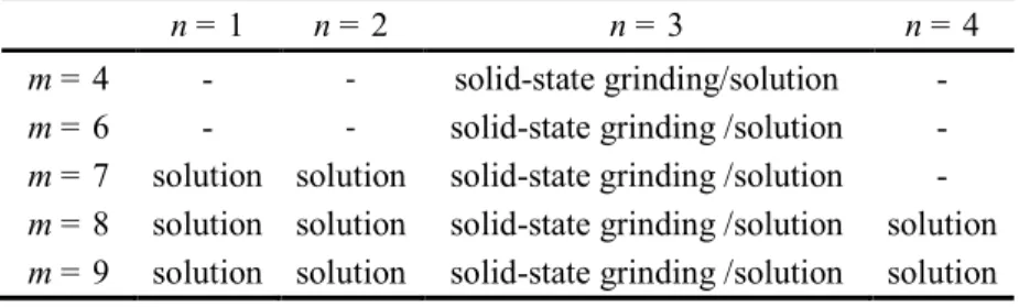
solution is too dilute or cooled down too rapidly. To mitigate these synthetic hurdles, we used two approaches, that involve both solution and solid-state synthesis, to achieve better kinetic control and successful synthesis of multilayer diammonium 2D perovskites, as discussed below. These two methods are complementary in providing a full picture on the synthetic strategies of accessing this family of compounds. All perovskite members synthesized in this report are summarized in Table 1.
Tuning of n by solution method. A closer examination of the previously reported solution synthesis
of n = 136 reveals that a relatively dilute solution (0.3 mmol Pb in 3 ml HI (0.1M)) was used to obtain
n = 1. Using that concentration to obtain multilayer perovskites results in the n = 1 or light-yellow
hydrate phases which are the least soluble products. Note that the solubility limit for MAPbI3 in HI is
~0.6M at boiling point. So we need to control that the concentration of Pb2+ and CH3NH3 +
ions is close to the solubility limit of MAPbI3 and the amount of solvent is enough to dissolve the n = 1
compound. This achieves a nearly saturated solution for a given multilayer compound, and it is subsequently possible to precipitate the multilayer perovskite from solution in pure form. We can thus successfully isolate the n > 1 perovskites for cations with m = 7 - 9. In a typical experiment of synthesizing (NH3CmH2mNH3)2(CH3NH3)n−1PbnI3n+1, stoichiometric amounts of PbO and CH3NH2·HCl
were dissolved in HI, according to the chemical formula, followed by addition of the diammonium diiodide salts in sub-stoichiometric ratios, depending on the solubility of the final products.19 If full stoichiometry amount of diiodide salts were used, lower layer-thickness compounds would be obtained because the solubility decreases with decreasing thickness of inorganic layers. A key synthetic condition to obtain the desired compound is to maintain the concentration of the solution near the saturation point under boiling. After a clear solution was obtained, the temperature was lowered to just below the boiling point of HI (125 ) ℃ and held there for several hours under reflux to prevent the undesirable light-yellow phase precipitation. On the other hand, since the solution is very concentrated, the desired product can still precipitate in a reasonable rate even though the solution is hot. Once the first deeply colored crystals (corresponding to the target compound) precipitate, the solution was cooled slowly to room temperature at ~2K/min rate.
The color of the crystals varies from orange (n = 1) to cherry red (n = 2) to dark red (n = 3) and black (n = 4). Successful synthesis of the desired layer-thickness was confirmed by powder X-ray 3 4 5 6 7 8 9 10 11 12 13 14 15 16 17 18 19 20 21 22 23 24 25 26 27 28 29 30 31 32 33 34 35 36 37 38 39 40 41 42 43 44 45 46 47 48 49 50 51 52 53 54 55 56
13
diffraction (PXRD) (Figure S1, S2), with the number of low angle Bragg peaks below ∼2θ=14° (incidentally) coinciding with the number of perovskite layers, as described previously for the (C4H9NH3)2(CH3NH3)n−1PbnI3n+1 series.
19
It is worth mentioning that the n = 1 for the odd carbon-chain members (m = 7, 9), which have not been reported previously, can also be obtained when using more concentrated solution than that used in the Billing’s procedure.36 Plate-shaped single crystals suitable for X-ray diffraction analysis of (NH3CmH2mNH3)(CH3NH3)n-1PbnI3n+1 (m = 8, 9 / n =
1 - 4) compounds can be obtained from this process regardless of odd and even carbon-chain diamines and the crystal structures will be discussed below.
The use of carbon chains with m = 4 and m = 6, however, still presents a synthetic challenge using the solution method described above, since the n = 1 phases are so insoluble they always precipitate out first, irrespective of the amount of the spacer cation and the Pb2+/CH3NH3
+
input ratio. To bypass this problem, solid-state grinding method 51-52 was employed in order to obtain the bulk materials (m = 4, 6 - 9, n = 3).
Tuning of chain length m using solid-state grinding. Since it is challenging to synthesize
multilayer perovskites for shorter carbon-chain members (m = 4 and 6) because of the poor solubility of n = 1, solid-state grinding method is utilized to fully explore diamines with all the carbon-chain numbers. Solid-state grinding, which has been used before for synthesizing 3D perovskites,51-52 is an ideal method for this, since all the starting materials must stay within the system and react, the low solubility issue of n = 1 prevalent in the solution method can be overcome. Also, since there is no water in the reaction, the hydrated phase can be avoided. Here, because of the very large number of members involved, we chose to focus only on the n = 3 compounds with different carbon-chain lengths (m = 4, 6 - 9) as proof-of-principle examples. Because the reaction during grinding depends on ionic diffusion, the reaction progress needs to be monitored periodically using PXRD and completion can be judged by the consumption of PbI2 before and after annealing.
Direct evidence that the proper 2D perovskite has formed with this method is provided by the existence of low angle Bragg peaks in PXRD corresponding to the number of layers below ∼2θ=14°, which is the same as what we have observed in PXRD of crystals from the solution method. In Figure S3, all n = 3 compounds obtained from solid-state grinding show the characteristic three low angle Bragg peaks below 2θ=14°. As the carbon-chain length m increases, the first peak shifts to 3 4 5 6 7 8 9 10 11 12 13 14 15 16 17 18 19 20 21 22 23 24 25 26 27 28 29 30 31 32 33 34 35 36 37 38 39 40 41 42 43 44 45 46 47 48 49 50 51 52 53 54 55 56 57
lower 2θ, confirming that the d-spacing between the inorganic layers also increases. Another supporting evidence that a 2D layered structure is indeed obtained by the solid-state grinding method is the morphology of the crystals shown by SEM images in Figure S4. Even though the crystal sizes (1-5 µm) are smaller than those obtained by the solution method, plate-shape and stacked-layer morphology can be clearly observed in the SEM images of the obtained powders, which are characteristic of 2D structured compounds.
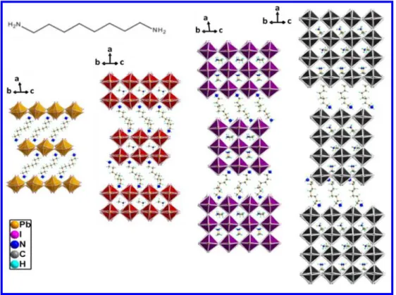
Description of crystal structures
Crystals from solution method (NH3CmH2mNH3)(CH3NH3)n-1PbnI3n+1 (m = 8, 9 / n = 1 - 4) were
selected and studied by single crystal X-ray diffraction. Because of the similarity of m = 8 and m = 9 series, only crystal structures of the (NH3C8H16NH3)(CH3NH3)n-1PbnI3n+1 (n = 1 - 4) compounds are
shown in Figure 1, and structures of (NH3C9H18NH3)(CH3NH3)n-1PbnI3n+1 (n = 1 - 3) are shown in
Supporting Information (Figure S6). Selected crystallographic information is presented in Table 2, with detailed crystallographic data provided in the Supporting Information (Table S1 - 6). All compounds crystallize in non-centrosymmetric monoclinic space groups, with Cc space group for even n members and Pc space group for odd n members. The di erence in odd and even ff n members
of the homologous 2D perovskites arises from the changes in the crystallographic symmetry element that bisects the perovskite layers themselves. For even n members a crystallographic mirror plane is present whereas for odd n numbers this is replaced by a glide plane.53 The unit cells have two short axes and one longer a axis, along which the 2D layers stack. For a primitive cell, the length of the longer axis can be estimated by the formula: a=6.3*n+x, where n is the layer-number and x is the length of the carbon chain in the cation (Table S7).
The inorganic layers with corner-sharing octahedra are separated by the organic spacers in the (100) direction, and the organic and inorganic parts are bound together by electrostatic interactions between the ammonium end group and the iodide anions. The organic spacer is long enough to tilt and allow the inorganic layers to slide in a staggered configuration, offset by half [PbI6]
octahedron (~3.2 Å), so they belong to the so-called Ruddlesden-Popper (RP) structure type. The organic spacer itself, adopts a folded conformation (Figure 2a), resembling a compressed spring pressed against two adjacent inorganic layers. This conformation is distinctively different from the interdigitating motif of the monoammonium cations the carbon chains of which adopt a stretched out conformation (Figure 3 4 5 6 7 8 9 10 11 12 13 14 15 16 17 18 19 20 21 22 23 24 25 26 27 28 29 30 31 32 33 34 35 36 37 38 39 40 41 42 43 44 45 46 47 48 49 50 51 52 53 54 55 56
15
2d).
When comparing the (NH3C8H16NH3)(CH3NH3)n-1PbnI3n+1 and (C4H9NH2)2(CH3NH3)n−1PbnI3n+1 series,
we find they have similar unit cells, since the d-spacing for one eight-carbon-chain diamine is close to that of two four-carbon-chain monoamines. The (C4H9NH2)2(CH3NH3)n−1PbnI3n+1 series adopt
orthorhombic space groups Cc2m and C2cb for even and odd n members, respectively, and the organic parts are restricted by the symmetry elements. For even n members, the organic atoms must be placed on the crystallographic mirror plane, while for odd layer-number the carbon atoms are related by the glide plane and the periodicity doubles. For (NH3CmH2mNH3)(CH3NH3)n-1PbnI3n+1 (m =
8, 9 / n = 1 - 4), if the structure is refined in the orthorhombic space group, the inorganic part can be satisfactorily modeled, but it is more challenging to define the position of the diammonium cations as these connect to both sides of adjacent inorganic layers. For even layer-number n = 2, 4, if the organic part is restrained along the mirror plane (Cc2m), the carbon-chain can only stretch in two dimensions, which results in conformation higher in energy (Figure 2b). For odd layer-number on the other hand, the glide plane between the two symmetry-equivalent spacer cations always generates even number of carbons, which creates a conflict for m = 9 when the orthorhombic space group (C2cb) is considered. Because of this, the symmetry needs to be lowered to the monoclinic space group of Cc for even n-members and Pc for odd n-members, so that the organic atoms can be independently refined in three dimensions, resulting in conformations of lower energy (Figure 2a). The lower symmetry allows for more degrees of freedom for the diammonium cations and this results in the folding of the carbon chain which, arguably, is a preferable conformation to the expanded straight carbon chain observed in other systems (Figure 2c).54 The folding of the diammonium cations, leads to a decrease in the interlayer spacing (compared to a straight chain) so that a monolayer of eight-carbon-chain diammonium cations is roughly equivalent in width to a bilayer of four-carbon-chain monoammonium cations (Figure 2d). The decrease in symmetry is statistically justified by the Hamilton significance test.55 An additional validation of the space group assignment comes from DFT calculations (see below).
Optical properties
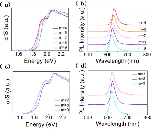
The optical properties for crystals from the solution method, (NH3CmH2mNH3)(CH3NH3)n-1PbnI3n+1 (m = 7 - 9 / n =1 - 4), are shown in Figure 3, and the bandgaps and photoluminescence (PL) peaks are
3 4 5 6 7 8 9 10 11 12 13 14 15 16 17 18 19 20 21 22 23 24 25 26 27 28 29 30 31 32 33 34 35 36 37 38 39 40 41 42 43 44 45 46 47 48 49 50 51 52 53 54 55 56 57
summarized in Table 3. The optical absorption spectra are typical of 2D perovskites, with a high-energy absorption edge and a low-energy excitonic peak. The excitonic behavior at room temperature, arises as a result of dielectric confinement between the insulating organic layers and the inorganic semiconducting layers to form a quantum well electronic structure, whereas a finite quantum confinement effect is observed due to the reduction of the perovskite dimensionality to few nanometers.56-57 Because of the existence of the exciton peaks, determination of the bandgaps for these materials is not as straightforward as in other semiconductors. In this case, we estimate the bandgap by extrapolating the high-energy absorption edge to imaginary axis parallel to the x axis where the absorption edge is interrupted by the low energy exciton peak.19, 58 The multilayer compounds tend to show similar bandgaps for m = 7 – 9, while for n = 1, m = 8 compound exhibits higher bandgap than the m = 7 and 9 compounds by 0.15 eV. This is because for n = 1 the inorganic layers of m = 8 compound is much more distorted than those of m = 9 , with Pb-I-Pb angle for m = 8 (147.44°) smaller than that of m = 9 (153.75°), so the bandgap of m = 8 are higher in energy than those of m = 9, following the same trend as previously reported.59 (more detailed discussion below). This shows that the organic cations can influence the distortion of the perovskite structure and consequently the optical properties.
Like other 2D perovskites, these compounds also display photoluminescence at room temperature (Figure 3), whose energy is close to the energy value of the excitonic peak in the absorption spectra and matches the PL peak position of the same layer-thickness in (C4H9NH3)2(CH3NH3)n−1PbnI3n+1
system.19 The lifetimes of the series were determined using time-resolved photoluminescence (TRPL) spectroscopy and were generally found to be shorter than 0.1 ns (Figure S7), which is close to the instrument response function (IRF) of the experiment (~38 ps) for the 1 ns window. The short recombination lifetime is approximately 3-5 times shorter than the values reported for (PEA)2(CH3NH3)n−1PbnI3n+1 (PEA=phenethylammonium) and (N-AMP)(CH3NH3)n−1PbnI3n+1 (N=3,4,
AMP= (aminomethyl)piperidinium) which have shown recombination lifetimes in the order of 100-200ps.41, 60
The optical properties of compounds from the solid-state grinding method (Figure 4a, b) are similar to those from solution method within the same layer-thickness (Figure 4c, d), except that the excitonic peaks are significantly suppressed. This may result from lower crystallinity and larger number of defects and grain boundaries of samples obtained from the solid-state grinding method. In fact, even 3 4 5 6 7 8 9 10 11 12 13 14 15 16 17 18 19 20 21 22 23 24 25 26 27 28 29 30 31 32 33 34 35 36 37 38 39 40 41 42 43 44 45 46 47 48 49 50 51 52 53 54 55 56
17
for crystals from the solution method, if the bandgaps are measured after grinding them in a mortar and pestle, the excitonic peaks become less obvious. The fact that the exciton peaks in the absorption spectra for crystals from solution method are more pronounced than those from the solid-state grinding method suggests that the excitons are better expressed in long-range ordered 2D lattices where the coherence of the quantum well is maintained. 56, 61
Band structure calculations
We calculated the electronic band structures using DFT for (NH3C8H16NH3)(CH3NH3)n-1PbnI3n+1 (n =1
- 4) (Figure 5). For all n values, the compounds exhibit a quasi-direct bandgap (see below) at the Γ point and features of 2D-like electronic structures with flat dispersions in the stacking direction. Around the gap, one can see the formation of n sub-bands for n = 1 - 4 indicating the slow decrease of quantum confinement with increasing n. Additionally, for n = 2 - 4, one can observe a band splitting around the valence band maximum and conduction band minimum as well as a slight shift away from Γ. Such a splitting is characteristic of a Rashba coupling arising from the simultaneous presence of large spin-orbit coupling and the polarity of the crystal lattice. 62 Besides, it is well known that DFT tends to largely underestimate band gaps. However, trends are usually correctly described. The calculated bandgaps are Eg=1.54 eV for n = 1, Eg=1.15 eV for n = 2, Eg=0.69 eV for n = 3 and Eg=0.08 eV for n = 4, following the experimental trend, as well as the trend observed in the RP
(C4H9NH3)2(CH3NH3)n−1PbnI3n+1 series, as the layer-number increases the bandgap decreases. The
electronic structures obtained here for diammonium cations are similar to those computed for monoammonium-based 2D perovskites, suggesting that the introduction of the diammonium cations with long enough alkyl chains (here m = 8) between the layers does not alter the basic qualitative electronic features of the 2D perovskite. 63,64
Comparing different classes of 2D perovskites
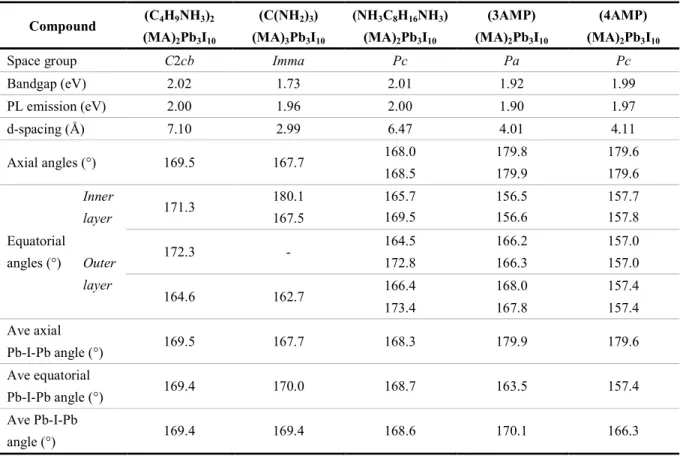
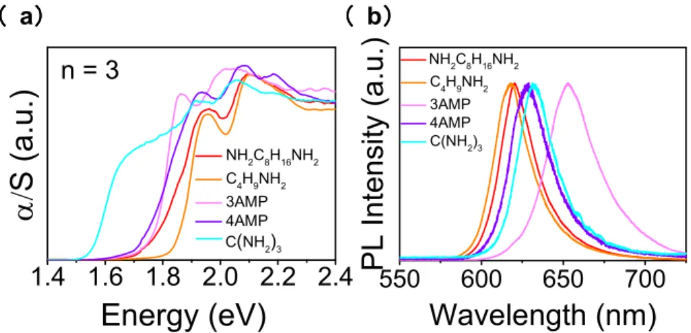
Comparing the optical properties of the present perovskites incorporating the diammonium cations with other 2D perovskites, we find that the optical properties are very close to the RP phase (C4H9NH3)2(CH3NH3)2Pb3I10 (summarized in Table 4). For n = 3, the PL emission peaks for
(NH3C8H16NH3)(CH3NH3)2Pb3I10 are similar with those of the reported perovskites
(C4H9NH3)2(CH3NH3)2Pb3I10 and (PEA)2(CH3NH3)2Pb3I10 at 2.00 eV, while for other reported
3 4 5 6 7 8 9 10 11 12 13 14 15 16 17 18 19 20 21 22 23 24 25 26 27 28 29 30 31 32 33 34 35 36 37 38 39 40 41 42 43 44 45 46 47 48 49 50 51 52 53 54 55 56 57
diammonium spacers such as (3AMP)(CH3NH3)2Pb3I10 and (4AMP)(CH3NH3)2Pb3I10
(AMP=(aminomethyl)piperidinium), they are at 1.90 eV and 1.97 eV, respectively (Figure 6). This is expected because the structures of (NH3C8H16NH3)(CH3NH3)2Pb3I10 are the same as the RP phase,
which indicates that it is the structure that determines the optical properties.
The precise distortion of the inorganic layer can also influence the bandgap, where the less distorted the structure, the larger the Pb−I−Pb bond angles, and the greater the Pb s and I p orbitals overlap. This causes larger bandwidths and consequently lowers the bandgap.59, 65 The Pb−I−Pb bond angles can be classified in two categories, equatorial along the inorganic plane and axial along the stacking axis. Equatorial Pb−I−Pb bonds are in the direction along the inorganic layer, where the charges transport across, thus should be more relevant to the bandgap. Axial Pb−I−Pb bonds are in the direction of the stacking axis, and they are likely to influence the excitonic behavior. Therefore, we mainly focus our discussion on equatorial Pb−I−Pb bond angles. We can easily observe that (NH3C8H16NH3)(CH3NH3)2Pb3I10 and (C4H9NH3)2(CH3NH3)2Pb3I10 have similar structures (average
equatorial Pb−I−Pb bond angles - 168.7° and 169.4°, respectively) and interlayer spacing (Table 4), and therefore it is not surprising that their bandgaps are almost the same.
For compounds with different structures, the Pb−I−Pb bond angles may not be the only determinant factor. Even though (NH3C8H16NH3)(CH3NH3)2Pb3I10 and(4AMP)(CH3NH3)2Pb3I10 have comparable
average Pb−I−Pb angles (168.6° and 166.3°, respectively), (4AMP)(CH3NH3)2Pb3I10 has smaller
equatorial Pb−I−Pb angles than (NH3C8H16NH3)(CH3NH3)2Pb3I10 , but it also exhibits smaller
bandgap because the interlayer spacing between inorganic layers for the AMP compounds are much smaller than (NH3C8H16NH3)(CH3NH3)2Pb3I10. Between (3AMP)(CH3NH3)2Pb3I10 and
(4AMP)(CH3NH3)2Pb3I10, (3AMP)(CH3NH3)2Pb3I10 has larger equatorial Pb−I−Pb angles resulting in
even lower bandgap than (4AMP)(CH3NH3)2Pb3I10. But both are more distorted than
(NH3C8H16NH3)(CH3NH3)2Pb3I10 and have lower bandgaps probably because of the shorter interlayer
spacing.41
Other series of compounds with similar Pb−I−Pb angles and small d-spacing, (C(NH2)3)(CH3NH3)nPbnI3n+1
33
and Cs(C(NH2)3)PbX4 (X=Br and I) 34
, also exhibit smaller bandgaps relative to widely spaced 2D perovskites for a given layer-number. Therefore, it is reasonable to assume that as the interlayer spacing decreases, such as in the case of AMP and C(NH2)3 series, the
interaction between the inorganic layers becomes stronger across the layers, which may decrease the 3 4 5 6 7 8 9 10 11 12 13 14 15 16 17 18 19 20 21 22 23 24 25 26 27 28 29 30 31 32 33 34 35 36 37 38 39 40 41 42 43 44 45 46 47 48 49 50 51 52 53 54 55 56
19
bandgap. However, more experimental crystal structures and optical spectra for the pure compounds as well as theory studies are needed before we can draw definitive conclusions on the role of the interlayer spacing to the evolution of bandgap in 2D perovskites.
Film fabrication
To test the potential of these materials for future device applications, we studied the formation of films using spin-coating of DMF solutions of all n = 3 compounds derived from the solid-state grinding method on glass substrates. If the solution was spin-coated directly by the one-step method,66 the Bragg intensities in the PXRD pattern were weak and their bandgaps varied significantly (Figure S8), suggesting they are likely to be mixtures of different layer-thickness numbers. It has been reported that adding HI to the precursor solution can disrupt the strong hydrogen bonding between solvent molecules and ammonium cations, affecting the evaporation rate and the perovskite crystallization rate.67 Therefore, in this work, we added 10% HI to the precursor solutions, with all the other details of film fabrication remaining the same as the method without the HI additive. After adding HI, the film morphology (Figure S9, S10) and intensity of PXRD patterns (Figure 7a) improved significantly. These films exhibited three low angle basal Bragg peaks below ∼2θ=14°, consistent with the n = 3 perovskite. The existence of low angle peaks for most of the films also indicates that the orientations of the films are not perfectly perpendicular to the substrate, with the exception of the m = 8 compound which exhibited the best preferred vertical orientation (discussed below). The optical absorption edges of these films were also much sharper (Figure 7b).
Crystal orientation in the thin-film examined by GIWAXS
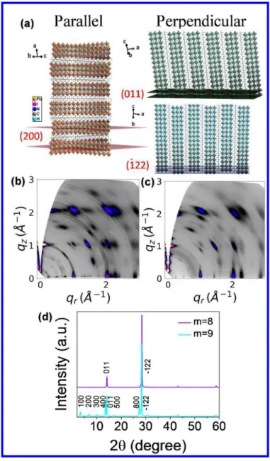
Because the understanding of thin-film crystal orientation and stability is necessary for future work on devices we assessed the crystallinity and orientation of the thin-films with GIWAXS analysis using synchrotron radiation. The GIWAXS maps for m = 4, m = 6 and m = 7 films show Bragg diffraction rings with some stronger intensities along certain extended arc segments (Figure S11), which suggests the thin-films are polycrystalline with almost random orientations. On the contrary, m = 8 and m = 9 films exhibit discrete Bragg spots (Figure 8b, 8c) indicating near-single-crystalline strong orientation vertical to the substrate. A closer comparison of m = 8 and m = 9 thin-films reveals the difference more clearly. The m = 8 thin-film shows weak intensity of the three low-angle diffraction peaks between qz = 0 - 1, whereas the intensity of these peaks is much higher for m = 9 in the same range.
3 4 5 6 7 8 9 10 11 12 13 14 15 16 17 18 19 20 21 22 23 24 25 26 27 28 29 30 31 32 33 34 35 36 37 38 39 40 41 42 43 44 45 46 47 48 49 50 51 52 53 54 55 56 57
The GIWAXS data are consistent with the conventional PXRD results (Figure 8d) obtained from the same thin-films, where the m = 9 film shows (h00), (011) and (-122) peaks, while the m = 8 shows only (011) and (-122) peaks (see Figure 8a for the labelling of the diffraction planes). The (h00) peaks correspond to the spots below qz=1 in GIWAXS map, while (011) and (-122) peaks correspond to the
spots at qz=1 and qz=2, respectively (Figure 8a). The fact that the intensity of the (-122) peak is higher
than that of (011) for the m = 8 thin-film suggests the inorganic layers are highly aligned perpendicular to the substrate. The occurrence of all the peaks indicate that m = 9 thin-film has orientations both parallel and perpendicular to the substrate (Figure 8a). The perpendicular film orientation is important for high performance solar cell applications because it allows the carriers to travel through the conducting inorganic layers across electrode, without being interrupted by the insulting organic layers.17, 68 The solar cell devices work is still ongoing and will be reported separately.
Film stability
Thermal, light and air stability were tested for all n = 3 films (Figure S12) and all the tests were conducted with the perovskite side of the film facing up. Thermal stability was tested on hot plates of 100 ℃ inside a N2 atmosphere glove box After continuous heating of 48 h, two low angle peaks
appeared in PXRD pattern for the m = 4 and m = 6 films, which suggests starting of decomposition. For m = 7 and m = 9, the three low angle peaks changed to a mixture of different layer numbers. The PXRD pattern for m = 8 remained intact after the thermal stability test, as well as after the light stability test under constant LED light in N2 atmosphere for 10 days and air stability (23.5 and 10%℃
(nominal) humidity) in the dark for 7 days. This shows that the m = 8 film has the best thermal, light and air stability among all n = 3 films.
Next, we compare the relative stability of the 3D MAPbI3 film and the m = 8 film under the same
conditions monitored by PXRD. While the MAPbI3 film starts to decompose to PbI2 from the fourth
hour under continuous heating at 100 and N℃ 2 atmosphere (Figure S13), the m = 8 film remained
stable for over 350 hours. We also conducted light stability tests in ambient condition under a solar simulator (1-sun intensity with 10% (nominal) humidity at 28 ℃) with the perovskite sides of the films facing up. After six hours, the MAPbI3 film already turned yellow and PbI2 peaks began to
appear in the PXRD pattern (Figure 9a). After twelve hours, the MAPbI film was completely yellow, 3 4 5 6 7 8 9 10 11 12 13 14 15 16 17 18 19 20 21 22 23 24 25 26 27 28 29 30 31 32 33 34 35 36 37 38 39 40 41 42 43 44 45 46 47 48 49 50 51 52 53 54 55 56
21
and the perovskite Bragg peaks almost disappeared. We have also tested the stability (C4H9NH3)2(CH3NH3)2Pb3I10 in order to establish the relative stability among the 2D perovskite
classes. After 6 hours, the PXRD for (C4H9NH3)2(CH3NH3)2Pb3I10 film remained almost intact but
the surface of the film started turning yellow. After 12 hours, the film turned completely yellow and the perovskite peaks almost disappeared (Figure 9b). By comparison the PXRD pattern of the m = 8 film remained intact for at least 24 hours and the film barely showed any color change (Figure 9c), clearly demonstrating that the perovskite film incorporating the diammonium cations has superior light stability over both 3D MAPbI3 perovskite films and 2D monoamines films. Note that these light
stability tests in air is a reliable way to decide which material is most stable under the ambient laboratory atmosphere, and it does not necessarily scale with the stability times reported previously for complete devices in the literature.17
Conclusions
The use of ditopic cations with two positive ends can act as effective spacers to stabilize the new 2D RP perovskite family. We have demonstrated the successful synthesis of (NH3CmH2mNH3)(CH3NH3)n-1PbnI3n+1 (m = 4 - 9 / n = 1 - 4) series with complementary solid-state
grinding and solution methods. The inorganic perovskite anionic slabs in these phases are held together in the third dimension by the electrostatic attractions of the ditopic cations rather than the weak van der Waals interactions of mono-cation organic spacers. In this sense the (NH3CmH2mNH3)(CH3NH3)n-1PbnI3n+1 are bridged in the third direction and are stronger than the more
familiar monocationic spacer perovskites. The solution method provides high-quality crystals for structural determination of the longer carbon-chain members (m = 7 - 9) while the solid-state grinding method works for all the carbon-chain numbers (m = 4 - 9). Structural characterization by single-crystal X-ray diffraction for (NH3CmH2mNH3)(CH3NH3)n-1PbnI3n+1 (m = 8, 9 / n = 1 - 4) reveals
that they belong to the Ruddlesden-Popper type, with space groups of Cc for even n members and Pc for odd n members. Optical properties of these materials are also similar to other 2D Ruddlesden-Popper perovskites. Successful fabrication of thin-films (n = 3) from solution was demonstrated. The m = 8 and m = 9 films show different orientations, with m = 8 having the almost perfect orientation perpendicular to the substrate. Film stability tests reveal that m = 8 film exhibits the best thermal, light and air stability within this series and far superior to the prototypical MAPbI3
3 4 5 6 7 8 9 10 11 12 13 14 15 16 17 18 19 20 21 22 23 24 25 26 27 28 29 30 31 32 33 34 35 36 37 38 39 40 41 42 43 44 45 46 47 48 49 50 51 52 53 54 55 56 57
itself. This finding sets the stage for future investigations of optoelectronic devices using this material.
Associated Content Supporting Information
More experimental details for X-ray diffraction, crystallographic details, thermal analysis (DSC and TGA), SEM images for powders, TRPL data and additional film characterization.
X-ray crystallographic data for (NH3C8H16NH3)(CH3NH3)n-1PbnI3n+1 (n = 2 - 4).
X-ray crystallographic data for (NH3C9H18NH3)(CH3NH3)n-1PbnI3n+1 (n = 1 - 3).
Author information Corresponding Author
*m-kanatzidis@northwestern.edu. *konstantinos.stoumpos@northwestern.edu
Notes
The authors declare no competing financial interest.
Acknowledgements
This work was supported by the Office of Naval Research, under Grant N00014-17-1-2231 (synthesis, structural characterization of materials, stability studies M.G.K.). PL lifetime measurements were supported by the ANSER Center, an Energy Frontier Research Center funded by the U.S. Department of Energy, O ce of Science, and ff O ce of Basic Energy Sciences under award DESC0001059 (ff W.K., M.C., M.R.W., film fabrication and PL lifetime measurements). Work at Los Alamos National Laboratory (LANL) was supported by the Laboratory Directed Research & Development program. This work was performed in part at the Center for Integrated Nanotechnologies, an Office of Science User Facility operated for the US DOE Office of Science. LANL, an affirmative-action equal opportunity employer, is operated by Los Alamos National Security for the National Nuclear Security Administration of the US DOE under contract DE-AC52-06NA25396. DFT calculations were performed at the Institut des Sciences Chimiques de Rennes, which received funding from Agence Nationale pour la Recherche (TRANSHYPERO project) and the work was granted access to the HPC resources of TGCC/CINES/IDRIS under the allocation 2017- A0010907682 made by GENCI. This work made use of the SPID (confocal microscopy) and EPIC (scanning electron microscopy) facilities of Northwestern University’s NUANCE Center, which has received support from the Soft and Hybrid 3 4 5 6 7 8 9 10 11 12 13 14 15 16 17 18 19 20 21 22 23 24 25 26 27 28 29 30 31 32 33 34 35 36 37 38 39 40 41 42 43 44 45 46 47 48 49 50 51 52 53 54 55 56
23
Nanotechnology Experimental Resource (NSF ECCS1542205), the Materials Research Science and Engineering Centers (NSF DMR-1121262), the International Institute for Nanotechnology (IIN), the Keck Foundation, and the State of Illinois through the IIN. Use of the Advanced Photon Source at Argonne National Laboratory was supported by the Basic Energy Sciences program of the US DOE Office of Science under contract DE-AC02-06CH11357.
References
1. Stoumpos, C. C.; Kanatzidis, M. G., Acc. Chem. Res. 2015, 48, 2791. 2. Stoumpos, C. C.; Kanatzidis, M. G., Adv. Mater. 2016, 28, 5778.
3. Kojima, A.; Teshima, K.; Shirai, Y.; Miyasaka, T., J. Am. Chem. Soc. 2009, 131, 6050.
4. Lee, M. M.; Teuscher, J.; Miyasaka, T.; Murakami, T. N.; Snaith, H. J., Science 2012, 338, 643.
5. Zhou, H.; Chen, Q.; Li, G.; Luo, S.; Song, T.-b.; Duan, H.-S.; Hong, Z.; You, J.; Liu, Y.; Yang, Y., Science
2014, 345, 542.
6. Yang, W. S.; Park, B.-W.; Jung, E. H.; Jeon, N. J.; Kim, Y. C.; Lee, D. U.; Shin, S. S.; Seo, J.; Kim, E. K.; Noh, J. H.; Seok, S. I., Science 2017, 356, 1376.
7. Arora, N.; Dar, M. I.; Hinderhofer, A.; Pellet, N.; Schreiber, F.; Zakeeruddin, S. M.; Grätzel, M., Science
2017, 358, 768.
8. Wang, N.; Zhao, K.; Ding, T.; Liu, W.; Ahmed, A. S.; Wang, Z.; Tian, M.; Sun, X. W.; Zhang, Q., Adv.
Energy Mater. 2017, 7, 1700522.
9. Gu, P.-Y.; Wang, N.; Wang, C.; Zhou, Y.; Long, G.; Tian, M.; Chen, W.; Sun, X. W.; Kanatzidis, M. G.; Zhang, Q., J. Mater. Chem. A 2017, 5, 7339.
10. Wang, N.; Liu, W.; Zhang, Q., Small Meth. 2018, 2, 1700380.
11. Tsai, H.; Asadpour, R.; Blancon, J.-C.; Stoumpos, C. C.; Durand, O.; Strzalka, J. W.; Chen, B.; Verduzco, R.; Ajayan, P. M.; Tretiak, S.; Even, J.; Alam, M. A.; Kanatzidis, M. G.; Nie, W.; Mohite, A. D., Science 2018,
360, 67.
12. Park, N.-G.; Grätzel, M.; Miyasaka, T.; Zhu, K.; Emery, K., Nat. Energy 2016, 1, 16152.
13. Slavney, A. H.; Smaha, R. W.; Smith, I. C.; Jaffe, A.; Umeyama, D.; Karunadasa, H. I., Inorg. Chem. 2017,
56, 46.
14. Domanski, K.; Alharbi, E. A.; Hagfeldt, A.; Grätzel, M.; Tress, W., Nat. Energy 2018, 3, 61.
15. Smith, I. C.; Hoke, E. T.; Solis-Ibarra, D.; McGehee, M. D.; Karunadasa, H. I., Angew. Chem. 2014, 126, 11414.
16. Cao, D. H.; Stoumpos, C. C.; Farha, O. K.; Hupp, J. T.; Kanatzidis, M. G., J. Am. Chem. Soc. 2015, 137, 7843.
17. Tsai, H.; Nie, W.; Blancon, J.-C.; Stoumpos, C. C.; Asadpour, R.; Harutyunyan, B.; Neukirch, A. J.; Verduzco, R.; Crochet, J. J.; Tretiak, S.; Pedesseau, L.; Even, J.; Alam, M. A.; Gupta, G.; Lou, J.; Ajayan, P. M.; Bedzyk, M. J.; Kanatzidis, M. G.; Mohite, A. D., Nature 2016, 536, 312.
18. Blancon, J.-C.; Tsai, H.; Nie, W.; Stoumpos, C. C.; Pedesseau, L.; Katan, C.; Kepenekian, M.; Soe, C. M. M.; Appavoo, K.; Sfeir, M. Y.; Tretiak, S.; Ajayan, P. M.; Kanatzidis, M. G.; Even, J.; Crochet, J. J.; Mohite, A. D., Science 2017, 355, 1288.
19. Stoumpos, C. C.; Cao, D. H.; Clark, D. J.; Young, J.; Rondinelli, J. M.; Jang, J. I.; Hupp, J. T.; Kanatzidis, M. G., Chem. Mater. 2016, 28, 2852. 3 4 5 6 7 8 9 10 11 12 13 14 15 16 17 18 19 20 21 22 23 24 25 26 27 28 29 30 31 32 33 34 35 36 37 38 39 40 41 42 43 44 45 46 47 48 49 50 51 52 53 54 55 56 57
20. Stoumpos, C. C.; Soe, C. M. M.; Tsai, H.; Nie, W.; Blancon, J.-C.; Cao, D. H.; Liu, F.; Traoré, B.; Katan, C.; Even, J.; Mohite, A. D.; Kanatzidis, M. G., Chem 2017, 2, 427.
21. Mao, L.; Tsai, H.; Nie, W.; Ma, L.; Im, J.; Stoumpos, C. C.; Malliakas, C. D.; Hao, F.; Wasielewski, M. R.; Mohite, A. D.; Kanatzidis, M. G., Chem. Mater. 2016, 28, 7781.
22. Ma, C.; Shen, D.; Ng, T.-W.; Lo, M.-F.; Lee, C.-S., Adv. Mater. 2018, 30, 1800710. 23. Yan, J.; Qiu, W.; Wu, G.; Heremans, P.; Chen, H., J. Mater. Chem. A 2018, 6, 11063.
24. Chen, Y.; Sun, Y.; Peng, J.; Zhang, W.; Su, X.; Zheng, K.; Pullerits, T.; Liang, Z., Adv. Energy Mater. 2017,
7, 1700162.
25. Yuan, M.; Quan, L. N.; Comin, R.; Walters, G.; Sabatini, R.; Voznyy, O.; Hoogland, S.; Zhao, Y.; Beauregard, E. M.; Kanjanaboos, P.; Lu, Z.; Kim, D. H.; Sargent, E. H., Nat. Nano. 2016, 11, 872.
26. Mao, L.; Wu, Y.; Stoumpos, C. C.; Wasielewski, M. R.; Kanatzidis, M. G., J. Am. Chem. Soc. 2017, 139, 5210.
27. Mao, L.; Wu, Y.; Stoumpos, C. C.; Traore, B.; Katan, C.; Even, J.; Wasielewski, M. R.; Kanatzidis, M. G.,
J. Am. Chem. Soc. 2017, 139, 11956.
28. Mitzi, D. B.; Feild, C. A.; Harrison, W. T. A.; Guloy, A. M., Nature 1994, 369, 467.
29. Calabrese, J.; Jones, N. L.; Harlow, R. L.; Herron, N.; Thorn, D. L.; Wang, Y., J. Am. Chem. Soc. 1991, 113, 2328.
30. Papavassiliou, G. C.; Mousdis, G. A.; Raptopoulou, C. P.; Terzis, A., Z. Naturforsch. B 2000, 55, 536. 31. Zhu, X.-H.; Mercier, N.; Riou, A.; Blanchard, P.; Frere, P., Chem. Commun. 2002, 2160.
32. Mercier, N., CrystEngComm 2005, 7, 429.
33. Soe, C. M. M.; Stoumpos, C. C.; Kepenekian, M.; Traoré, B.; Tsai, H.; Nie, W.; Wang, B.; Katan, C.; Seshadri, R.; Mohite, A. D.; Even, J.; Marks, T. J.; Kanatzidis, M. G., J. Am. Chem. Soc. 2017, 139, 16297. 34. Nazarenko, O.; Kotyrba, M. R.; Wörle, M.; Cuervo-Reyes, E.; Yakunin, S.; Kovalenko, M. V., Inorg. Chem.
2017, 56, 11552.
35. Li, L.; Sun, Z.; Wang, P.; Hu, W.; Wang, S.; Ji, C.; Hong, M.; Luo, J., Angew. Chem., Int. Ed. 2017, 56, 12150.
36. Lemmerer, A.; Billing, D. G., CrystEngComm 2012, 14, 1954. 37. Lemmerer, A.; Billing, D. G., CrystEngComm 2010, 12, 1290. 38. Tang, Z.; Guan, J.; Guloy, A. M., J. Mater. Chem. 2001, 11, 479.
39. Mousdis, G. A.; Papavassiliou, G. C.; Raptopoulou, C. P.; Terzis, A., J. Mater. Chem. 2000, 10, 515. 40. Rayner, M. K.; Billing, D. G., Acta Crystallogr. E 2010, 66, m660.
41. Mao, L.; Ke, W.; Pedesseau, L.; Wu, Y.; Katan, C.; Even, J.; Wasielewski, M. R.; Stoumpos, C. C.; Kanatzidis, M. G., J. Am. Chem. Soc. 2018, 140, 3775.
42. Gate, L. F., Appl. Opt. 1974, 13, 236.
43. Petříček, V.; Dušek, M.; Palatinus, L., Z. Kristallogr. 2014, 229, 345. 44. Spek, A., Acta Crystallogr. D 2009, 65, 148.
45. José, M. S.; Emilio, A.; Julian, D. G.; Alberto, G.; Javier, J.; Pablo, O.; Daniel, S.-P., J. Phys.: Condens.
Matter 2002, 14, 2745.
46. Emilio, A.; Anglada, E.; Diéguez, O.; Gale, J. D.; García, A.; Junquera, J.; Martin, R. M.; Ordejón, P.; Pruneda, J. M.; Sánchez-Portal, D.; Soler, J. M., J. Phys.: Condens. Matter 2008, 20, 064208.
47. Zhang, Y.; Yang, W., Phys. Rev. Lett. 1998, 80, 890. 48. Troullier, N.; Martins, J. L., Phys. Rev. B 1991, 43, 1993.
49. Artacho, E.; Sánchez Portal, D.; Ordejón, P.; García, A.; Soler, J. M., ‐ Phys. Stat. Sol. (b) 1999, 215, 809.
50. Fernández-Seivane, L.; Oliveira, M. A.; Sanvito, S.; Ferrer, J., J. Phys.: Condens. Matter 2006, 18, 7999.
3 4 5 6 7 8 9 10 11 12 13 14 15 16 17 18 19 20 21 22 23 24 25 26 27 28 29 30 31 32 33 34 35 36 37 38 39 40 41 42 43 44 45 46 47 48 49 50 51 52 53 54 55 56