ISMRE2018/XXXX-2018 ALGERIA
Effect of iron doping on tin oxide thin films
1st Leila Segueni,2nd Boubaker Benhaoua,3rd Nassiba Allag,4th Achour Rahal,5th Atmane Benhaoua 1st Lab.VTRS,Faculty of Technology, Univ. El-Oued
2nd Renewable Energy Research Unite in Arid zones Univ. El-Oued 3rd Faculty of Science Technology, Univ. Biskra
4th Lab.VTRS,Faculty of Technology, Univ. El-Oued 5th Lab.VTRS,Faculty of Technology, Univ. El-Oued Corresponding Author email address:[email protected]
Abstract— In this study, Undoped tin oxide (SnO2) and iron
(Fe) doped tin oxide thin films were deposited on heated glass using spray pyrolysis technique. SnCl2 and FeCl3 were used as
sources of SnO2 and Fe doping respectively. Effects of dopant
on the optical, structural and opto-electrical properties of 0,0.2 and 0.4 wt.% Fe-doped SnO2 thin films were investigated.
Optical transmittance spectra of the thin films showed high transparency of about 80-90% in visible region. The optical gap of 0,0.2and 0.4 wt. % Fe-doped SnO2 thin films were found
to be in 3.78-3.67 eV range. X-ray diffraction patterns showed that both undoped SnO2 and Fe-doped SnO2 thin films, were
polycrystalline with cassiterite tetragonal crystal structure. The preferential orientation for undoped SnO2 was along (211)
plane whereas Fe-doped SnO2 preferential orientations were
along (110) planes. The calculated grain sizes were in 35.63-30.03 nm average. Fe-doped SnO2 thin films are promising to
be used as smart windows , gas sensor and water treatment.
Keywords— Spray pyrolysis, FeTO thin films, SnCl2 precursor, X-ray diffraction, UV-Visible Spectroscopy Four-point probe technique, TCOs.
I. INTRODUCTION
Transparent conductive oxides (TCOs) are interesting materials for several applications, such as electrical conductivity and transparency in the visible region, make them important for photovoltaic cells, optoelectronics and catalytic applications [1-3]. SnO2 as TCO is available materiel and easy to deposit as thin films using several techniques such as chemical vapor deposition[4], sol-gel[5], pulsed laser deposition[6] and spray pyrolysis[7]. Among the different TCOs, SnO2 films doped with Iron seem to be the most proper used for those applications, The spray pyrolysis method may be the most convenient technique because of its modestly, easy to add doping materials and promising for high rate and produced large quantity [8].
Doping with, Iron (Fe), antimony (Sb), cobalt (Co), Cerium (Ce), fluorine (F), palladium (Pd), niobium (Nb), molybdenum (Mo) and indium (In) has been achieved to improve tin oxide (SnO2) properties [9-15]. The dopant with iron from chloride iron(FeCl3), has been shown to be the most achieved commercial use due to its simplicity and low cost.
In this work, 0,0.2 and 0.4wt. % iron doped tin oxide (Fe-doped SnO2) were prepared by spray pyrolysis technique on glass substrates using SnCl2 and FeCl3 as sources of SnO2 and iron doping respectively. The aim of this work is to study the effect of the dopant rate of FeTO thin films on structure, optical transmittance and electrical. Obtained results are compared and discussed with the specified results carried out by several researchers.
II. EXPERIMENTAL METHODS
A. Solutions and thin films preparation
SnO2 thin films were prepared from a solution of tin dichloride (SnCl2). The precursor concentration, was 0.5M ,which served as a starting solution. Iron doping was carried out by adding, appropriate amount of chloride iron (FeCl3) dissolved in doubly distilled water, to the starting solution until arriving to 0,0.2 and 0.4 wt. % iron concentrations in mixture solution. The mixture solution was stirred at room temperature. The obtained blend was used as a stock solution for spray pyrolysis. The starting solution and blend solution were sprayed separetely on heated glass substrates by spray pyrolysis system [8] leading to undoped SnO2 and Fe doped SnO2 thin films.
III. RESULTS AND DISCUSSION
A. Optical properties
Fig.1 shows UV-vis transmittance spectra of undoped and Iron doped SnO2 thin films with various dopant rates .The transmittance of all samples was less than 90% along visible region (400 - 800nm). As seen in Fig.1, the films show an decrease in transmittance after doping with iron at 0,0.2 and 0.4 wt. %.
Fig.2 shows the estimated optical band gap (Eg) of 0,0.2 and 0.4 wt. % Fe doped SnO2 thin films with different dopant rates associated with the inset of undoped one. Eg values were deduced from transmission measurements using Tauc’s relation [20]:
where hν is the photon energy, A is a constant which does not depend on hν, (Eg) is the optical band gap. For undoped and iron doped Eg values were deduced from the optical transmission by extrapolating (αhν)2
= 0, they founed to be ranged in 3.78~3.67eV as recapitulated in Table I. The optical band gap values are higher than the value, (Eg= 3.78eV), reported for single crystal SnO2 [21]. This decrease in optical band gap may be attributed to an decrease in carrier concentration of the films due to Fe doping revealing Burstein-Moss effect [22, 23].
Fig. 1. Transmittance spectra of 0,0.2 and 0.4 wt.% Fe doped
SnO2 thin films .
TABLE I. Films thickness, transmittance, and optical band
gap Eg values for 0,0.2 and0.4 wt. % Fe doped SnO2 thin films.
Material Thickness t (nm) Transmittance T (%) Band gap Eg (eV) Undoped film SnO2: Fe (0.2 wt. %) SnO2: Fe (0.4 wt. %) 311.29 321.54 316.94 90.12 83.61 79.15 3.78 3.65 3.67
Fig. 2. Band gap (Eg) estimation from Tauc relation of 0,0.2 and
0.4 wt. % Fe doped SnO2 thin films for different dopant rates.
B. Structural properties
X-ray diffraction patterns of the SnO2 films deposited by spry pyrolysis with different dopant are shown in Fig.3. As can be seen all the films are polycrystalline, five major peaks corresponding to the tetragonal SnO2 (JCPDS No. 41-1445). All deposited thin films have SnO2 tetragonal rutile structure, and no phase corresponded to iron was observed. From XRD results of our SnO2 thin films one can observe that for Fe doped films with 0,0.2 and 0.4 wt.% the prominent planes were (211); the others observed peaks, with weak intensities, were (101), (211), (310) and (301). whereas, for the undoped film, the prominent plane was (211). We use the texture coefficient TC(hkl) which represents the texture of the particular plane, deviation of which from unity implies the preferred growth. The different texture coefficients TC(hkl) have been calculated from the X-ray data using the well-known formula [24]:
N nI hkl I hkl N hkl I hkl I hkl TC ) ( / ) ( ) ( / ) ( ) ( 0 1 0 where TC(hkl) is the texture coefficient of the plane (hkl), I(hkl) is the measured intensity I0(hkl) is the standard
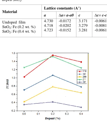
intensity of the plane (hkl) taken from the JCPDS data, N is the reflection number and n is the number of diffraction peaks. Fig. 4 shows the texture coefficients TC(hkl). It is perceptible from that the undoped SnO2 film grows along the preferred orientation of (211) whereas all Fe doped SnO2 thin films with different dopant rates grow along (110) plane. The lattice constants ‘a’ and ‘c’, for the tetragonal phase structure were determined from XRD results using the following equation [25]: 2 2 2 2 2 2 1 c l a k h dhkl
where dhkl is the shortest distance between two plans of the family hkl, (hkl) are the Miller indexes and ‘a’ and ‘c’ are the lattice constants. The calculated and standard lattice constants are illustrated in Table II. The calculated ‘a’ values are less than that given by JCPDS card No: 41-1445 (a0= b0 = 4.737 Å); whereas, all values of the lattice constants ‘c’ are marginally slightly less than that of JCPDS card (c0= 3.185 Å). Further, the lattice parameters of undoped SnO2 thin film are, a = b = 4.730Å and c = 3.171 Å; we noted that the lattice parameter ‘a’ is decreased after iron doping. Changes in a and c values may be attributed to (Fe+3 ionic radius = 0.64Å) substitution of (Sn +4 ionic radius = 0.71 Å) [26].
Fig. 3. XRD patterns of 0, 0.2 and 0.4 wt. % Fe doped SnO2 films
TABLE II. . Lattice parameters a, c, of 0, 0.2 and 0.4 wt. % Fe
doped SnO2.
Material Lattice constants (A°)
a ∆a= a-a0 c ∆c= c-c0 Undoped film SnO2: Fe (0.2 wt. %) SnO2: Fe (0.4 wt. %) 4.730 4.718 4.723 -0.0172 -0.0202 -0.0152 3.171 3.279 3.281 -0.0061 -0.0081 -0.0061
Fig. 4. TC(hkl) variation of 0,0.2 and 0.4 wt.% Fe doped SnO2 thin films.
The crystalline sizes of Fe doped SnO2 thin films, were calculated from highly textured peaks by using Scherrer’s formula [27]: cos 9 . 0
D
where D is the crystallite size, λ is the X-ray wavelength (1.54056 A°) ,β is the full width at half-maximum (FWHM) of the most intense diffraction peak and θ is the Bragg angle. Scherrer’s equation applied to the most intense (211) and
(110) diffraction lines for the undoped and Fe doped films respectively reveals that D size distribution is about 35.63 nm for the undoped film whereas for Fe doped ones D sizes distributions are between 35.63-30.03 nm.
C. Opto-electrical studies
Fe doped SnO2 thin films were less conducting at room temperature with resistivity values much more than of undoped SnO2 one. The four-point probe is favored for measurement of sheet resistance (Rsh); in the linear four-point probe technique, the current (I) is applied between the outer two leads and the potential difference (V) is measured across the inner two probes [8], so can obtain a fairly accurate estimation of Rsh using the following relation:
4.532( ) I V
Rsh
K=4.532 correction factor was applied for the sample (1 cm×1 cm) with equally spaced (≈1mm) probes and the film thickness necessarily being less than the spacing between the probes. Table III gives Rsh values of the undoped and Fe doped SnO2; as can be seen Rsh values of Fe doped SnO2 thin films are relatively higher than the undoped SnO2. This means that the highest sheet resistance has the highest electrical conductivity.
TABLE III. Variation of sheet resistance (Rsh) and resistivity
values of 0,0.2 and 0.4 wt% Fe doped SnO2 thin films..
Material Rsh (Ω) Resistivity(Ω cm) Undoped film SnO2: Fe (0.2 wt. %) SnO2: Fe (0.4 wt. %) 500.98 1500.63 2941.51 1.2×10⁻⁴ 1.7×10⁻³ 1.2×10⁻³ IV. CONCLUSION
Undoped SnO2 and iron doped SnO2 with different dopant rates were sprayed pyrolysis on 480°C heated glass substrates with moving nozzle . Effects of films dopant on the optical, structural and opto-electrical properties of 0,0.2 and 0.4 wt. % Fe-doped SnO2 thin films were investigated. The average transmittance of all samples was less than 90% in the visible region. The optical band gap for undoped and SnO2: Fe films were found to be in the range 3.78-3.67 eV. X-ray characterization revealed that the undoped SnO2 films were polycrystalline with cassiterite tetragonal crystal structure and have preferential orientations along (211) planes, whereas FeTO thin films have preferential orientations along (110) planes. The calculated grain sizes, for both undoped and doped thin films, lied in the average of 35.63-30.03 nm. The obtained low conducting and transparent FeTO thin films are promising to be useful in various optoelectronic applications, in particular, as smart window in solar cells and water treatment.
ACKNOWLEDGMENT
This work was supported in part by RERUAZ Renewable Energy Research Unit in Arid Zones El-Oued University. X-ray diffraction data in this work were acquired with an instrument supported by the University of Biskra. We thank Prof. Abdelouahed Chala and B. Gasmi (Biskra University) for the assistance in XRD data acquisition.
REFERENCES
[1] S. Sujatha Lekshmy, G.P. Daniel, K. Joy, Microstructure and physical properties of sol gel derived SnO2: Sb thin films for optoelectronic applications, Applied Surface Science 274 (2013) 95–100.
[2] J. Clerk. E. Elangovan, K. Ramamurthi, Optoelectronic properties of spray deposited SnO2: F thin films for window materials in solar cells, Journal of Optoelectronics and Advanced Materials Vol. 5, No. 1, (2003) 45 – 54.
[3] G.D. Khuspe, R.D. Sakhare, S.T. Navale, M.A. Chougule, Y.D. Kolekar, R.N. Mulik, R.C. Pawar, C.S. Lee, V.B. Patil, Nanostructured SnO2 thin films for NO2 gas sensing applications, Ceramics International 39 (2013) 8673 – 8679.
[4] J. Szuber, G. Czempik, R. Larciprete, B. Adamowicz, The comparative XPS and PYS studies of SnO2 thin films prepared by L-CVD technique and exposed to oxygen and hydrogen, Sensors and Actuators B 70 (2000) 177–181.
[5] H. Köse, A.O. Aydin and H. Akbulut, Sol–Gel synthesis of nanostructured SnO2 thin film anodes for Li-Ion batteries, Acta Physica Polonica A 121(2012) 227-229.
[6] Ch.J. Lee, J.H. Lee, J.J. Kim, J.Y. Lee and H.Y. Lee, SnO2: CuSb2O6 thin films prepared by pulsed laser deposition, Integrated Ferroelectrics 115 (2010) 34–40.
[7] K. Murakami, K. Nakajima, S. Kaneko, Initial growth of SnO2 thin film on the glass substrate deposited by the spray pyrolysis technique, Thin Solid Films 515 (2007) 8632–8636.
[8] A. Benhaoua, A. Rahal, B. Benhaoua, M. Jlassi, Effect of fluorine doping on the structural, optical and electrical properties of SnO2 thin films prepared by spray ultrasonic, Superlattices and Microstructures 70 (2014) 61–69.
[9] Ch.M. Wang, Ch.C. Huang, J.Ch. Kuo, J.L. Huang, Investigation of pulsed ultraviolet laser annealing of Sb/SnO2 thin films on the structural, optical and electrical properties, Surface & Coatings Technology 231 (2013) 374 –379.
[10] G. Korotcenkov, I. Boris, V. Brinzari, S.H. Han, B.K. Cho, The role of doping effect on the response of SnO2-based thin film gas sensors: Analysis based on the results obtained for Co-doped SnO2 films deposited by spray pyrolysis, Sensors and Actuators B 182 (2013) 112–124.
[11] Z. Jiang, Z. Guo, B. Sun, Y. Jia, M. Li, J. Liu, Highly sensitive and selective butanone sensors based on cerium-doped SnO2 thin films, Sensors and Actuators B 145 (2010) 667–673.
[12] B. Zhu, Ch. Yin, Z. Zhang, Ch. Tao, Liu Yang, Investigation of the hydrogen response characteristics for sol–gel-derived Pd-doped, Fe-doped and PEG-added SnO2 nano-thin films, Sensors and Actuators B 178 (2013) 418–425.
[13] G. Turgut, E.F. Keskenler, S. Aydın, E. Sönmez ,S. Dogan, B. Düzgün and M. Ertugrul, Effect of Nb doping on structural, electrical and optical properties of spray deposited SnO2 thin films, Superlattices and Microstructures 56 (2013) 107–116.
[14] E. Zampiceni , E. Bontempi , G. Sberveglieri and L. E.Depero, Mo influence on SnO2 thin films properties, Thin Solid Films 418 (2002) 16–20.
[15] L. Francioso, A. Forleo, S. Capone, M. Epifani, A. M. Taurino, P. Siciliano, Nanostructured In2O3–SnO2 sol–gel thin film as material for NO2 detection, Sensors and Actuators B 114 (2006) 646–655. [16] E. Elangovan, K. Ramamurthi, A study on low cost-high conducting
fluorine and antimony-doped tin oxide thin films, Applied Surface Science 249 (2005) 183–196.
[17] A. Muthukumar, G. Giusti, M. Jouvert, V. Consonni, D. Bellet, Fluorine-doped SnO2 thin films deposited on polymer substrate for flexible transparent electrodes, Thin Solid Films 545 (2013) 302–309. [18] J.C. Manifacier, M. de Murcia, J.P. Fillard, optical and electrical
properties of SnO2 thin films in relation to their stoichiometric deviation and their crystalline structure, thin Solid Films 41 (1977) 127-135.
[19] D.R. Acosta, E.P. Zironi, E. Montoya, W. Estrada, About the structural, optical and electrical properties of SnO2 films produced by spray pyrolysis from solutions with low and high contents of fluorine, Thin Solid Films 288 (1996) 1-7.
[20] J. Tauc, The optical properties of solids, (J. Tauc, ed.), Academic Press, New York (1966) 277.
[21] R. Summit, J.A. Marley, N.F. Borrelli, The ultraviolet absorption edge of stannic oxide (SnO2), Journal of Physics and Chemistry of Solids 25 (1964) 1465 – 1469.
[22] E. Burstein, Anomalous optical absorption limit in InSb, Physical Review 93 (1954) 632-633.
[23] T.S. Moss, The interpretation of the properties of Indium Antimonide, Proceedings of the Physical Society London B76 (1954) 775-782. [24] C. S. Barret, T. B. Massalski, Structure of Metals, Pergamon Press,
Oxford,1980.
[25] C. Marcel, N. Naghavi, G. Couturier, J. Salardenne, J. M. Tarascon, J. Appl. Phys. 91 (2002) 4291.
[26] M.-M Bagheri-Mohagheghi, N. Shahtahmasebi, M.R. Alinejad, A. Youssefi, M. Shokooh-Saremi,"Fe-doped SnO2 transparent semi-conducting thin films deposited by spray pyrolysis technique : Thermoelectric and p-type conductivity properties",Solid State Sciences 11(2009) 233-239.