Development and implementation
of a methodology for hybrid fire testing
applied to concrete structures
with elastic boundary conditions
Thesis submitted in partial fulfillment of the requirements for the degree of Doctor of Philosophy in Applied Sciences by
Ana SAUCA
December 2016
Development and implementation
of a methodology for hybrid fire testing
applied to concrete structures
with elastic boundary conditions
Thesis submitted in partial fulfillment of the requirements for the degree of Doctor of Philosophy in Applied Sciences by
Ana SAUCA
December 2016
Supervisor
Prof. Dr. Ir. Jean-Marc Franssen
Co-Supervisor
Prof. Dr. Ir. Boyan Mihaylov
Research institute
Structural Engineering unit Department ArGEnCo Faculty of Applied Sciences University of Liege, Belgium
Examination committee Prof. Dr. Ir.
Jean-Pierre Jaspart (chairman)
University of Liege, Belgium Faculty of Applied Sciences
Department ArGEnCo Structural Engineering
Prof. Dr. Ir.
Jean-Marc Franssen (supervisor)
University of Liege, Belgium Faculty of Applied Sciences
Department ArGEnCo Structural Engineering
Prof. Dr. Ir. Boyan Mihaylov (co-supervisor)
University of Liege, Belgium Faculty of Applied Sciences
Department ArGEnCo Structural Engineering
Dr. Ir.
Thomas Gernay
University of Liege, Belgium Faculty of Applied Sciences
Department ArGEnCo Structural Engineering Prof. Dr. Ir.
Nicola Tondini
University of Trento, Italy Department of Civil, Environmental and Mechanical Engineering Dr. Ir.
Fabienne Robert
CERIB, France Fire Testing Center
Prof. Dr. Ir. Hervé Degée
Hasselt University, Belgium Faculty of Engineering Technology
Research funding
The author would like to acknowledge CERIB for financial support of this thesis.
ABSTRACT
i
ABSTRACT
Fire tests remain a precious tool to comprehend the behavior of structures under accidental fire conditions. The common practice in fire testing is to isolate the tested element in a furnace in which the mechanical support conditions are maintained constant throughout the test. However, such tests fail to capture the effect of the structure surrounding the element of interest when this effect cannot be realistically modeled by a free or fixed support condition. It has been observed in large-scale tests that the behavior of entire structures under fire is different compared with the behavior observed in traditional tests on isolated elements. This indicates the importance of capturing accurately the boundary conditions between the element and the remainder of the structure when characterizing the behavior of this element in fire. The literature describes a few attempts at performing fire tests under realistic boundary conditions. In the latter, the tests were still performed on isolated elements but the boundary conditions were updated during the test taking into account the characteristics of the remainder structure. This technique, called hybrid testing, represents an appealing solution to test structural elements under realistic boundary conditions.
Hybrid testing is a methodology which offers the advantage of testing singular structural elements (or a group of structural elements) named physical substructure PS while at the same time considering the characteristics of the remainder substructure named numerical NS, thus allowing to model realistic boundary conditions. Pioneering work has been done in the seismic field where this technique is now well described, but the implementation of this methodology for structural fire testing raises important challenges due to the specificities of the field. A few hybrid fire tests have been performed in the past on columns and slabs. Their analysis shows that they all use a similar methodology, which is referred to as the first generation method in this work.
The objective of the thesis was to develop and implement a hybrid fire testing methodology on a reinforced concrete beam extracted from a moment resisting frame. Initially, it was intended to build on the first generation method, but after its detailed analysis in the development stage it has been observed that the process can be unstable. The value of the stiffness ratio between the numerical substructure and the physical substructures has been identified as critical in governing the stability of the test, dictating whether the hybrid test needs to be applied in displacement control or force control. This is a severe drawback of the first generation method, as the stiffness ratio is unknown and changing during the test; besides that, different degrees-of-freedom can require different procedures during the test. Therefore, it has been shown that the first generation method should not be applied as it can lead to instability prematurely during the tests.
To overcome the drawbacks of the first generation method, the objective was to develop a new technique that leads to interface equilibrium and compatibility while at the same time is unconditionally stable (i.e. independently of the stiffness ratio). Thus a new methodology was developed and applied to the case of a concrete beam (PS) being part of a concrete moment
ii
resisting frame (NS). The new method makes use of the PS’s stiffness in addition to the NS’s stiffness as it was the case in the first generation method. The stiffness matrix of the PS is unknown during the test therefore the initial tangent stiffness matrix is considered during the calculations. The latter choice influences the value of the time step to be adopted during the test. Every time step the boundary conditions are updated and it will be discussed how the chosen value can influence the results.
A predetermined matrix is used to describe the behavior of the NS during the hybrid fire tests. This approach does not capture the nonlinearity of the remainder but at the same time the implementation is relative simple and the negative effect of the time calculation is eliminated. The procedure to compute the predetermined matrix of the NS is presented in this thesis. One possible direction in the future development of hybrid fire testing is to model the NS in a finite element model.
The algorithm of the proposed method is developed and implemented in the nonlinear finite element software SAFIR in order to perform virtual hybrid fire tests. The same algorithm is translated in order to be implemented by the company in charge of the control system at the CERIB furnace facility.
The thesis also presents a traditional fire test that has been performed on the beam, in order to highlight the differences when testing structural element without and with the real boundary conditions. For the hybrid test, three degrees-of-freedom are controlled at the interface. The furnace facility has an important role to perform successful test where the equilibrium and compatibility are ensured and no instability occurs during the test. The impediments encountered during the tests will be discussed along with the recommendation for a successful hybrid fire test.
Keywords: fire, substructures, physical substructure, numerical substructure, boundary
ACKNOWLEDGMENT
iii
ACKNOWLEDGMENT
I am grateful to my advisor, Dr. Jean Marc Franssen, for his guidance and support throughout my doctoral studies. He is tremendous mentor and someone who I will always admire. He is the ONE who always had an answer for my questions accompanied by the best advice I could receive. I enjoyed every moment being part of the Fire Safety Engineering group and I am thankful that “you made something out of me”.
I am thankful to my dissertation committee members, Dr. Jean-Pierre Jaspart, Dr. Boyan Mihailov, Dr. Thomas Gernay, Dr. Nicola Tondini, Dr. Fabienne Robert, Dr. Hervé Degée for their helpful advice in preparing this thesis. Dr. Boyan Mihailov was the co-supervisor of the thesis and I am grateful for all the help. Dr. Vincent Denoël and Dr. Jean François Demonceau offered valuable advices during the preparation and I express my appreciation. I am particularly thankful to Dr. Robert Fabienne and Dr. Tessier Christophe. You were the first persons to believe in me and you offered me unbelievable support. I am fortunate to have had the possibility to learn from mentors like you and to be part of the CERIB family.
Dr. Thomas Gernay was the most perfect office colleague, one of the best researchers I know and moreover an incredible friend. I enjoyed working with you, I enjoyed our discussions and jokes and I have no words to express my gratitude for you. I am thankful for every advice and by the way, you know that you deserve all the chocolate from the world.
Cedric Collignon, Eric Leroy, Rija Niry, and Fabien Dumont helped immensely with the design and conduct of my project. They were always available for questions and devoted long hours of effort to help set up the specimens and taught me many technical skills.
The Fire Safety Engineering group, i.e. Anthony Scifo, Joao Ferreira, Elke Mergny, Eric Wellens, and Adil Ouardani, was a joy to work with. Their generosity and expertise created unique work environment.
I spent valuable time at CERIB with great people around from whom I learn all I know about the experimental work. I thank them for always making my stay there amazing and for sharing with me the French culture and not only.
I am particularly grateful to Dr. Oreste Bursi, Dr. Nicola Tondini and Dr. Giuseppe Abbiati who shared with me their experience on hybrid simulations.
My friends and ULg colleagues Anas, Andreea, Christophe, Daniela, Emil, Emna, Hélène, Hicham, Jian, Laura, Lina, Marina, Quang, Ruben, Teo, Timothée created a pleasant environment. I enjoyed our lunch discussions, holidays, gym or dancing nights, and I will always carry with me the memory of this amazing years.
iv
Daniela, Dan, Oana, Getush, Lena, Maria, Melinda, Tudor si Morar have been always supportive and dear friends. I am thankful to Dr. Hortensiu Liviu Cucu and Dr. Mihai Nedelcu who believed in me more than anyone.
I am the most grateful to my beloved family who has been continuously supportive. My dear mom and dad “Mamuska tai Neneka”, my brother Ivan and my sister in law Maria, I am extremely fortunate to have you and my love goes to you.
Support for this project was provided by CERIB. Any opinions, findings, and conclusions expressed herein are those of the author.
TABLE OF CONTENTS v
TABLE OF CONTENTS
ABSTRACT ... i ACKNOWLEDGMENT ... iii TABLE OF CONTENTS ... v LIST OF FIGURES ... ixLIST OF TABLES ... xiii
1. INTRODUCTION ... 1
1.1. Motivation of performing hybrid fire tests ... 1
1.2. The influence of the boundary conditions on the fire test results ... 2
1.3. Problem definition ... 6
1.4. Research objectives and scope ... 6
1.5. Organization of the thesis ... 7
2. HYBRID SIMULATION FUNDAMENTALS ... 9
2.1. Introduction ... 9
2.2. Components and procedure ... 10
2.3. Advantages and challenges ... 13
2.4. Seismic vs. Hybrid Fire Testing ... 14
2.5. Numerical and experimental errors ... 15
2.6. History of hybrid testing in the seismic field ... 16
2.7. State of the art in the fire field ... 19
2.8. Summary ... 30
3. CHARACTERISTICS OF THE HYBRID FIRE TESTING ... 33
3.1. Introduction ... 33
3.2. The supports of the PS and NS ... 33
3.3. The global versus local degrees-of-freedom... 38
3.4. The Representation of the Numerical Substructure ... 42
3.5. Time scale definition ... 46
3.6. Influence of the errors in the results ... 47
3.7. Criterion for stability and accuracy ... 53
vi
4. THE FIRST GENERATION METHOD ... 55
4.1. Introduction ... 55
4.2. Characteristics of the first generation method ... 55
4.2.1. Definition of the case study and nomenclature ... 55
4.2.2. The force control procedure ... 56
4.2.3. The displacement control procedure ... 58
4.3. Discussion ... 60
4.3.1. Analysis of the first generation method ... 60
4.3.2. Use of the first generation method in the previous hybrid fire tests ... 62
4.4. Numerical example ... 63
4.4.1. The correct solution of the interface... 63
4.4.2. Instability of the first generation method ... 64
4.4.3. Graphic representation ... 70
4.4.4. Error estimation for the first generation method ... 75
5. PROPOSED METHOD FOR HFT: THE SECOND GENERATION METHOD ... 91
5.1. Introduction ... 91
5.2. Theoretical background of the second generation method ... 93
5.2.1. FETI method. Description. Characteristics ... 93
5.2.2. Flowchart of the FETI method ... 98
5.2.3. Equilibrium and compatibility at ambient temperature ... 101
5.3. Development of the second generation method ... 102
5.3.1. Theoretical formulation ... 102
5.3.2. The steps of the new methodology ... 103
5.3.3. Implemented algorithm in CERIB fire facility ... 104
5.3.4. Local versus global system of coordinates in the new methodology ... 114
5.4. Numerical example. Simple elastic truss ... 114
5.4.1. The influence of the time step on the results ... 118
5.4.2. Influence of the tangent stiffness matrix of the PS on the results ... 123
5.4.3. Influence of the stiffness ratio on the results ... 128
5.4.4. Conclusions ... 130
5.5. Particularities of the new method in force versus displacement control ... 131
6. HYBRID SIMULATION CASE STUDY ... 137
TABLE OF CONTENTS
vii
6.2. Case study ... 138
6.2.1. Description ... 138
6.2.2. The definition of the predetermined matrix ... 141
6.3. The configuration of the tests ... 145
6.4. Numerical Analysis of the Hybrid Test (Virtual Hybrid Fire Testing) ... 146
6.4.1. The First Generation Method ... 148
6.4.2. The New Method in displacement control procedure ... 150
6.4.3. The New Method in force control procedure ... 172
6.5. Hybrid simulation at CERIB equipment site ... 174
6.6. Test 1 ... 176
6.6.1. Motivation ... 176
6.6.2. Test Setup and Procedure ... 176
6.6.3. Test Results and Interpretation ... 177
6.7. Test 2 ... 178
6.7.1. Motivation ... 179
6.7.2. The analysis of the testing equipment ... 179
6.7.3. Test Setup and Procedure ... 186
6.7.4. Test Results and Interpretation ... 187
6.7.4.1. The input data of the algorithm ... 187
6.7.4.2. Preloading stage ... 191
6.7.4.3. Equilibrium at ambient conditions ... 199
6.7.4.4. Post-analysis of the Test 2 ... 201
6.7.4.5. Summary of the Test 2 ... 217
6.8. Test 3 ... 218
6.8.1. Motivation and Description ... 218
6.8.2. The testing equipment ... 218
6.8.3. Test Setup and Procedure ... 220
6.8.4. Solution proposed to increase the axial force ... 220
6.8.5. Test Results and Interpretation ... 221
6.8.5.1. The input data of the algorithm ... 221
6.8.5.2. Preloading stage ... 222
6.9. Summary ... 224
viii
7.1. Summary ... 227
7.2. Conclusion ... 229
7.3. Future work ... 230
REFERENCES ... 233
A. APPENDIX A: CERIB FIRE FACILITY ... 241
A1. The dimensions of the furnace ... 241
A2. Mechanical characteristics ... 241
A3. Other specific characteristics ... 242
B. APPENDIX B: LOCAL VERSUS GLOBAL SYSTEM OF COORDINATES IN THE NEW IMPLEMENTED METHODOLOGY SPECIFIC TO CERIB FIRE FACILITY ... 243
C. APPENDIX C: MATERIALS AND CONSTRUCTION OF THE PS ... 253
C.1. Materials ... 253
C.2. Construction of the specimens ... 254
D. APPENDIX D: TEST SETUP ... 257
D.1. Beam preparation ... 257
D.2. Furnace preparation ... 257
LIST OF FIGURES
ix
LIST OF FIGURES
Figure 1-1. The evolution of mid-span displacement in different testing configurations of the beam
structural element ... 5
Figure 2-1. Components of hybrid fire testing ... 11
Figure 2-2. Substructuring method applied at BAM, Germany (excerpt from Korzen [58]) ... 20
Figure 2-3. Results of the hybrid fire test performed by Korzen (excerpt from Korzen [58]) ... 21
Figure 2-4. Experimental set-up to tests columns at FCTUC (excerpt from Korzen [59]) ... 22
Figure 2-5. The configuration of the considered structure (excerpt from Robert [64])... 23
Figure 2-6. The set-up of the PS (excerpt from Robert [64]) ... 24
Figure 2-7. The presented results of the hybrid fire test (excerpt from Robert [64]) ... 25
Figure 2-8. The configuration of the structural system used by Mostafaei (excerpt from Mostafaei [66]) ... 25
Figure 2-9. HFT loop presented by Mostafaei (excerpt from Mostafaei [66]) ... 26
Figure 2-10. Axial load versus the axial displacement during the hybrid fire tests presented by Mostafaei. (excerpt from Mostafaei [66]) ... 27
Figure 2-11. Hybrid model with mechanical and thermal loading scheme. The ZWIck UTM and Konn Furnace (excerpt from Whyte et al. [67] ) ... 28
Figure 2-12. Case study when FETI method is numerically applied (excerpt from Tondini et al. [72]) ... 29
Figure 2-13. Benchmark test for combined thermo-mechanical consolidated fire testing (excerpt from Schulthess et al. [72]) ... 30
Figure 3-1. Supports and boundary conditions in hybrid fire testing ... 34
Figure 3-2. Analyzed structure versus substructures. Sufficient number of link supports ... 35
Figure 3-3. Analyzed structure versus substructures. Insufficient link supports for the PS and NS ... 36
Figure 3-4. Analyzed structure versus substructures. Insufficient number of link supports for the PS 36 Figure 3-5. Analyzed structure versus substructures. Insufficient link supports for the NS ... 37
Figure 3-6. Experimental element. Global versus local DoFs . ... 39
Figure 3-7. Example of transformation of displacements from the global system of coordinates to the local system of coordinates ... 40
Figure 3-8. Local reaction forces versus global reaction forces ... 41
Figure 3-9. Experimental element. Global versus local DOFs . ... 42
Figure 3-10. The linearization of the nonlinear behavior ... 44
Figure 3-11. FE model and the predetermined matrix used to represent the NS ... 45
Figure 3-12. Time scale for hybrid fire testing ... 47
Figure 3-13. The accuracy in hybrid simulation ... 49
Figure 3-14. Reaction forces versus displacements of the PS for different time steps ... 49
Figure 3-15. Hybrid fire testing iteration process. ... 50
Figure 3-16. Influence of the time step on the results in the iteration process. ... 52
Figure 4-1. Linear elastic system... 56
x
Figure 4-3. One step of displacement control procedure. First generation method. ... 60
Figure 4-4. The boundary conditions when using a force control procedure (𝑅 < 1) ... 65
Figure 4-5. The boundary conditions when using a force control procedure (𝑅 > 1) ... 66
Figure 4-6. The boundary conditions when using a displacement control procedure (𝑅 < 1) ... 68
Figure 4-7. The boundary conditions when using a displacement control procedure (𝑅 > 1) ... 68
Figure 4-8 Graphic representation of the PS and NS for the time 𝑡0 ... 71
Figure 4-9 Graphic representation of the first read of displacement (FCP) ... 71
Figure 4-10 Graphic representation when computing the reaction of the NS for the time 𝑡1 (FCP) .... 72
Figure 4-11 Graphic representation of the new force and displacement induced in the PS for the time 𝑡1 + ∆𝑡𝑃 ... 73
Figure 4-12 Graphic representation of the first read 𝑡1 (DCP) ... 74
Figure 4-13 Graphic representation when computing the displacement of the NS for the time 𝑡1 ... 74
Figure 4-14 Graphic representation of the new force and displacement induced in the PS for the time 𝑡1 + ∆𝑡𝑃 ... 75
Figure 4-15. The evolution in time of interface force and displacement when the time step ∆𝑡 varies 78 Figure 4-16. The evolution in time of the interface forces and displacement when the delay time ∆𝑡𝑃 varies ... 80
Figure 4-17. Evolution of the boundary conditions when 𝑅 > 1 and ∆𝑡 varies in DCP ... 82
Figure 4-18. The evolution in time of the interface forces/displacements when the time step ∆𝑡𝑃 varies ... 85
Figure 4-19. Evolution of interface forces and displacements for different stiffness ratios (FCP) ... 87
Figure 4-20. Evolution of interface forces versus displacements for different stiffness ratios R (DCP) ... 90
Figure 5-1. FETI method ... 100
Figure 5-2. The procedure to restore equilibrium at ambient temperature ... 110
Figure 5-3. New method of hybrid fire testing. ... 113
Figure 5-4. Interface conditions when the stiffness ratio 𝑅 < 1 ... 115
Figure 5-5. Interface conditions when the stiffness ratio 𝑅 > 1 ... 116
Figure 5-6. Interface conditions when the stiffness ratio 𝑅 < 1 and the stiffness of the PS degrades 117 Figure 5-7. Interface conditions when the stiffness ratio 𝑅 > 1 and the stiffness of the PS degrades 117 Figure 5-8. Interface conditions when 𝑅 < 1 and the time step varies ... 120
Figure 5-9. Interface conditions when 𝑅 > 1 and the time step varies ... 121
Figure 5-10. The boundary conditions when 𝑅 < 1 and the stiffness of the PS varies ... 124
Figure 5-11. The boundary conditions when 𝑅 > 1 and the initial tangent stiffness of the PS varies 127 Figure 5-12. The boundary conditions when the stiffness ratio varies ... 130
Figure 5-13. The simple elastic system ... 132
Figure 5-14. Interface conditions for elastic system. Displacement control procedure. ... 134
Figure 5-15.Interface conditions for elastic system. Force control procedure. ... 135
Figure 6-1. Plan view of the building ... 138
Figure 6-2. Elevation of the structure. Section S-S ... 138
Figure 6-3. The cross section of the column ... 139
Figure 6-4. The sectional configuration of the beam... 139
Figure 6-5. FE model (SAFIR) of the analyzed structure. ... 141
Figure 6-6. The PS extracted from the analyzed structure ... 142
LIST OF FIGURES
xi
Figure 6-8 – Moment resisting concrete frame. ... 145
Figure 6-9 – The configuration of the physical specimen PS. ... 145
Figure 6-10. The case study results in a virtual environment when the first generation method is considered ... 149
Figure 6-11. Virtual HFT when 𝑡 = 1 𝑠 and 𝐾𝑃 ∗= 1.50𝐾𝑃 ... 157
Figure 6-12. Virtual HFT when 𝑡 = 10 𝑠 and 𝐾𝑃 ∗= 1.50𝐾𝑃 ... 158
Figure 6-13. Virtual HFT when 𝑡 = 30 𝑠 and 𝐾𝑃 ∗= 1.50𝐾𝑃 ... 160
Figure 6-14. Virtual HFT when 𝑡 = 60 𝑠 and 𝐾𝑃 ∗= 1.50𝐾𝑃 ... 162
Figure 6-15. Virtual HFT when 𝑡 = 300 𝑠 and 𝐾𝑃 ∗= 1.50𝐾𝑃 ... 163
Figure 6-16. Virtual HFT when 𝑡 = 600 𝑠 and 𝐾𝑃 ∗= 1.50𝐾𝑃 ... 164
Figure 6-17. The increment of the interface displacements and rotations ... 165
Figure 6-18. Incremental displacement and rotations when time step is 1 s, 10 s and 30 s ... 166
Figure 6-19. Virtual HFT when 𝑡 = 1 𝑠 and 𝐾𝑃 ∗= 5𝐾𝑃 ... 168
Figure 6-20. Virtual HFT when 𝑡 = 1 𝑠 and 𝐾𝑃 ∗= 10𝐾𝑃 ... 169
Figure 6-21. Virtual HFT when 𝑡 = 1 𝑠 and 𝐾𝑃 ∗= 50𝐾𝑃 ... 171
Figure 6-22. Virtual HFT when 𝑡 = 1 𝑠 and 𝐾𝑃 ∗= 50𝐾𝑃 ... 172
Figure 6-23. Interface conditions when force control procedure is considered ... 173
Figure 6-24. Architecture of the equipment site at CERIB-Promethee ... 174
Figure 6-25. Promethee fire laboratory ... 176
Figure 6-26. Temperature evolution in the longitudinal rebars ... 177
Figure 6-27. The beam after the fire exposure. ... 178
Figure 6-28. The evolution of the mid-span vertical displacements in Test 1 ... 178
Figure 6-29. The measurement of the horizontal displacement and rotation during the Test 2 ... 180
Figure 6-30. The system used to check the resolution of the transducers ... 182
Figure 6-31. Resolution of the transducers ... 183
Figure 6-32. The actuators controlling the support rotations ... 183
Figure 6-33. The actuator controlling the horizontal displacement ... 184
Figure 6-34. Test transducer using the actuator ... 185
Figure 6-35. The variation of displacement in time while controlling actuator ... 185
Figure 6-36. The measured displacements and rotations during the Test 2 ... 186
Figure 6-37. The configuration of the horizontal jacks ... 187
Figure 6-38. The mid-span load in the preloading stage 1 and 2 ... 192
Figure 6-39. The axial force in the preloading stage 1 and 2 ... 192
Figure 6-40. The axial displacement in the preloading stage 1 and 2 ... 193
Figure 6-41. The vertical forces in the preloading stage 1 and 2 ... 193
Figure 6-42. The rotations in the preloading stage 1 and 2 ... 194
Figure 6-43. The mid-span load in the preloading stage 3 ... 196
Figure 6-44. The axial force in the preloading stage 3 ... 196
Figure 6-45. The horizontal displacements in the preloading stage 3 ... 197
Figure 6-46. The forces in the vertical jacks in the preloading stage 3 ... 197
Figure 6-47. The support rotations in the preloading stage 3 ... 198
Figure 6-48. The intuitive procedure to compute and impose displacement ... 208
Figure 6-49. The considered procedure to computed displacements during Test 2 ... 209
Figure 6-50. Restoring of the equilibrium at ambient temperature. Measured versus computed values of PS ... 210
xii
Figure 6-51. The boundary conditions when the measured displacements are considered in the
calculation process ... 212
Figure 6-52. The influence of the resolution on the axial DoF in different stages of the test (the measured displacement considered in the calculations) ... 213
Figure 6-53. The boundary conditions when the measured displacements are neglected in the calculation process ... 215
Figure 6-54. The influence of the resolution on the axial DoF in different stages of the test (the measured displacement in the furnace is neglected) ... 215
Figure 6-55. The new system to measure the horizontal displacement in the TEST 3 ... 219
Figure 6-56. The load cell placed on the horizontal jack ... 220
Figure 6-57. The structural system proposed for the TEST 3. ... 221
Figure 6-58. The failure mode of the beam in the TEST 3 ... 223
Figure A-1. Promethee furnace. ... 241
Figure B-1. The data acquisition system used by Promethee ... 243
Figure B-2. The transfer system used by Promethee ... 244
Figure B-3. The sign convention of the inclinometer ... 245
Figure B-4. The sign convection for the transducers... 245
Figure B-5. The sign convention for jacks ... 246
Figure B-6. The definition of the global system of coordinates ... 246
Figure B-7. Position of the jacks compared with the axis of the GSC. ... 247
Figure B-8. Body loaded with forces ... 247
Figure B-9. Representation of the transducer ... 248
Figure B-10. The position of transducer compared with the axis of the GSC ... 248
Figure B-11. Body loaded with displacements ... 249
Figure B-12. The GCS and the positive rotation ... 249
Figure B-13. The position of the inclinometers in rapport with the global system of coordinates ... 250
Figure B-14. The GCS and the positive moment ... 250
Figure B-15. The induces moment in the furnace compared with the global moment ... 251
Figure C-1. Assembled reinforced cage of the beam ... 254
Figure C-2. The measuring junction of the sheathed type K thermocouples thermocouples ... 254
Figure C-3. The thermocouples used in the instrumentation of the beams ... 255
Figure C-4. The casting process ... 256
Figure C-5. The beam stored and transported to the furnace ... 256
Figure D-1. Preparation of the PS. ... 257
Figure D-2. The supports of the beam ... 258
Figure D-3. The measured displacements and rotations during the tests (configuration used during the Test 1) ... 258
Figure D-4. The instrumentation for displacement/rotation measurements (configuration used during the Test 1) ... 259
Figure D-5. The configuration of the jacks ... 259
LIST OF TABLES
xiii
LIST OF TABLES
Table 1-1. Possible test configuration for beam structural elements ... 2
Table 2-1. Hybrid simulation in seismic versus fire field ... 15
Table 4-1. The characteristics of the linear elastic system ... 56
Table 4-2. Measured and calculated data for one DoF case study ... 60
Table 6-1. Longitudinal reinforcement and the nominal cover of the beam ... 140
Table 6-2. Existing loads ... 140
Table 6-3. Description of the jacks and controlled DoFs ... 146
Table 6-4. The variation of the time step in the virtual hybrid fire testing... 155
Table 6-5. The variation of the PS’s stiffness in the virtual hybrid fire testing ... 167
Table 6-6. Stages of loading TEST 2 ... 191
Table 6-7. Interface displacement/rotation in Stage 1 ... 194
Table 6-8. Measured values in the TEST 2 ... 198
Table 6-9. Interface forces at ambient temperature in the Test 2 ... 199
Table 6-10. Interface displacements at ambient temperature in the Test 2 ... 200
Table 6-11. Displacements computed in SAFIR in configuration 1 (no tensile strength) ... 202
Table 6-12. Displacements computed in SAFIR in configuration 2 (with tensile strength) ... 202
Table 6-13. Reaction computed in SAFIR in Configuration 1 (no tensile strength) ... 203
Table 6-14. Reaction computed in SAFIR in Configuration 2 (with tensile strength) ... 203
Table 6-15. The measured displacements and reaction forces at the starts of the calculations in the GSC ... 206
Table 6-16. The computed displacements in the first iteration ... 207
Table 6-17. The arguments to decide the type of the transducers in the TEST 3 ... 218
Table 6-18. Loading of the PS in the TEST 3 ... 223
Table C-1. The composition of the concrete for m3 ... 253
INTRODUCTION
1
1.
INTRODUCTION
1.1. Motivation of performing hybrid fire tests
The construction field is growing in terms of structural solutions and new material. In order to prevent catastrophic events, which can occur under accidental actions, the behavior of different types of structures in extreme conditions should be assessed by civil engineers. The ability to analyze the behavior of a structure under accidental loads requires first the knowledge of the material behavior. New materials or new structural elements made of well-known materials need to be tested in order to validate and calibrate the new models and methodologies.
Fire tests are required to understand the behavior of structures exposed to fire. Generally the fire tests are performed on single elements, with no restraint, neglecting the action of the remainder structure [1], [2]. Entire structures have been tested [3]-[5] but the high cost makes the practice uncommon. Keeping the advantage of testing only parts of the structure, but at the same time to consider the global behavior of the structure, hybrid fire testing methodology is a promising technique.
Hybrid testing is a methodology inspired from substructuring procedure, and can have applicability under different loading conditions caused by wind, blast, impact, waves, fire, traffic and seismic events. Even if the methodology can be used for many cases of loading conditions, only in seismic field important research has been done in this direction since early 1970s. The implementation of a method developed from the seismic field to the fire field remains a challenge and only a few hybrid fire tests have been performed. Laboratories such as BAM (Germany), CERIB (France) and NRC (Canada) have the experimental facilities that would allow, provided a proper methodology is available, to carry out Hybrid Fire Testing (HFT).
Here are just few of the reasons supporting the necessity of fire tests in general and hybrid fire tests in particular. Globally, the thermal expansion of the structural elements exposed to fire induces important changes in the structural behavior during the fire test. The changes are dependent on the boundary conditions adopted in the test. Locally, specific phenomenon occurs for some materials when exposed to fire such as the spalling of the concrete. This phenomenon is yet impossible to be numerically modeled therefore the fire tests in the appropriate conditions are required to comprehend the action along with the structural behavior. Hybrid fire testing is the key to get more realistic results of the tests and to understand the real behavior of structures exposed to fire, under real boundary conditions. Despite the large amount of existing information related to hybrid testing in other fields, the application in the fire tests is not straightforward. This is due to the main characteristic of hybrid fire testing which requires hybrid tests performed in real time. The effect of the fire on the materials is immediate and continuous and the thermal expansion implies modification of the interface boundary conditions in real time. Thus the main challenge of hybrid fire testing
2
is to be able to develop a methodology specifically suited for the fire field which can be used in practice.
Therefore the objective of the thesis is to investigate the theoretical aspect of the methodology which can provide accurate results and ensure compatibility and equilibrium at the interface of the tested substructure and the remainder structure in real time. Next, the proper methodology will be implemented in a fire facility furnace followed by the experimental testing.
It is desired to develop the methodology to fully take advantage of the variety of the instrumentation devices, versatile equipment existing in the worldwide laboratories.
1.2. The influence of the boundary conditions on the fire test results
This section illustrates the capability of hybrid fire testing to capture the global behavior of the analyzed structure when testing individual structural elements.For exemplification, the behavior of a concrete beam exposed to fire is next analyzed in different test configurations. The exposed beam is a structural component of a moment resisting frame, a common structure in practice.
The most common practice when testing structural elements is to ensure free or fixed boundary conditions. Different support conditions are possible, depending on the furnace facility. Table 1-1 present the configurations available when testing a beam exposed to fire.
Table 1-1. Possible test configuration for beam structural elements
INTRODUCTION 3 Configuration 2 Configuration 3 Configuration 4 Configuration 5
4
Configuration 6
Configuration 1 refers to full scale testing when only the roof beam of the span number two is exposed to fire.
Configuration 2 represents the most common practice in the worldwide testing facilities. The beam is simply supported and loaded with equivalent forces such that the mid-span bending moment from the Configuration 1 is reproduced.
Configuration 3 is similar to Configuration 2. The beam is simply supported and in addition to the previous configuration, the supports bending moments are reproduced during the tests. The support bending moments are induced by the vertical jacks acting on the cold cantilever beam. The fire acts in between the supports and all the forces are constant during the entire test duration.
Configuration 4 presents the beam test when the support rotations are fixed and the thermal expansion is free.
In the test Configuration 5, the support rotations as the thermal expansion are fixed. The difference between the Configuration 4 and Configuration 5 is the fixation or not of the thermal expansion.
In the tests performed in the Configuration 1 to Configuration 5, all the forces are constant during the test.
The Configuration 6 is characteristic to hybrid fire testing. The support bending moments are applied by the vertical forces acting on the cantilever cold beam while the horizontal restrain of the surrounding structure is modeled via the horizontal force. Therefore, the action of the surrounding on the beam during the test is simulated by the vertical and horizontal forces. These forces vary during the tests depending on the characteristics of the tested elements and the characteristics of the rest of the structure. The vertical forces acting in the span of the beam are constant during the tests.
The beam is numerically modelled in the nonlinear software SAFIR in the specified configuration, in order to observe the behavior during the fire exposure. The standard fire exposure is considered, i.e. ISO 834, and the interest is to observe the time failure and failure mode.
INTRODUCTION
5
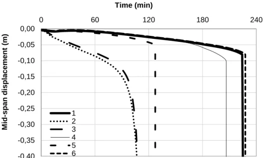
Figure 1-1. The evolution of mid-span displacement in different testing configurations of the beam structural element
Figure 1-1 presents the evolution in time of the mid-span displacement, in different configurations.
Similar results can be observed when testing the beam in Configuration 2 and Configuration 3. The distribution of the bending moment is different in the mentioned configurations and this is the reason of the small differences. The beam experiences ductile failure around 100 min since the start of the fire.
The beam tested in the Configuration 4 reproduces the behavior of the beam when full scale tested, until approximately 150 min since the beginning of fire. The failure occurs soon after 200min of fire exposure, with 100 min later than in the case of the simply supported beam. When the boundary conditions of the beam are fixed, with no possibility of thermal expansion i.e. Configuration 5, the failure occurs around 130 min.
When performing hybrid fire testing, i.e. Configuration 6, the behavior of the full scale testing is reproduces with small differences. The difference is due to the hypothesis accepted to perform the hybrid fire test. More details about how the hybrid fire test was numerically modelled will be presented in the next chapters.
For this specific case studied, the provided results by means of hybrid fire testing reproduce the real behavior better than the other possible mentioned configurations.
The time failure along with the mode failure depends on the configuration of the fire tests. During full scale testing the measured mid-span displacement is smaller compared with the mid-span displacement measured in the Configuration 2 and 3.
When performing hybrid fire testing, the mid-span displacement reaches the same range of values than in the case of the full scale testing.
-0,40 -0,35 -0,30 -0,25 -0,20 -0,15 -0,10 -0,05 0,00 0 60 120 180 240 M id -span d isplac ement ( m) Time (min) 1 2 3 4 5 6
6
Not only a variation of failure time depending on the test configuration is observed, but the failure mode can be different. A ductile failure is characteristic for tests performed in the Configuration 2 or Configuration 3, while in all the other configurations the failure is brittle.
From all the possible tests configurations presented in this section, the global behavior is reproduced only by means of hybrid fire testing. The advantage of the hybrid fire testing compared with the full scale testing derives from the possibility to perform test on individual structural elements but at the same time to reproduce the global behavior. During the hybrid fire test, the effect of the surrounding is considered.
This section shows the importance and the capability of hybrid fire testing in order to capture the global behavior during the fire tests. All the other configurations reveal different behavior and different failure time compared with the real situations. A better understanding of structures exposed to fire can be provided only by means of hybrid fire testing.
1.3. Problem definition
Hybrid fire testing methodology must be validated for different structural elements, must be stable during the entire test, to ensure equilibrium and compatibility at the interface of the substructures and to reproduce the global behavior of the building.
Only few hybrid fire tests have been performed in the past when physically testing columns and slabs. The behavior of the surrounding structure is modeled by using a predetermined matrix (assuming elastic behavior) or nonlinear numerical software (which allows capturing the nonlinear behavior).
The authors of the former hybrid fire tests used methods tailored to suit their particular needs, without verifying the applicability for generic application.
Therefore there is a need of developing and implementing a method which is unconditionally stable, to ensure interface equilibrium and compatibility and to generate accurate results and to be valid for all types of configurations and members.
1.4. Research objectives and scope
The aim of the research was to investigate, develop and validate hybrid fire testing and to permit hybrid testing to address to more complex problems to be investigated, independently on the characteristics of the substructures, being stable during the test. To achieve the purpose, the research has been conducted following the objectives presented here bellow.
1. Review and evaluation of the existing concepts and frameworks in hybrid fire testing. 2. Review and evaluation of the existing concepts and frameworks in hybrid
methodology developed in seismic field. A comparison between the seismic and fire fields is done, as well as the identification of the sources which suit the fire field. 3. Development of an unconditionally stable method to be suitable for various
configurations and which provides correct results.
4. The implementation of the new method in CERIB fire testing facility. 5. The experimental validation of the method on a case study.
INTRODUCTION
7
1.5. Organization of the thesis
This thesis is organized as follows:Chapter 1 underlines the motivation to perform hybrid fire testing, defines the problems to be solved and the objectives of the current thesis.
Chapter 2 provides general information about hybrid fire testing. It starts describing the procedure and the components of the hybrid fire testing, underlining the advantages and challenges of the procedure. The particularities of hybrid fire testing are visible when making the comparison of the hybrid simulation in fire field versus seismic field. Intensive research has been performed in seismic field and the history of the hybrid simulation method is presented followed by the state of the art in the fire field.
In Chapter 3, the characteristics of the hybrid fire testing are discussed, such as, the global versus local system of coordinates, the representation of the numerical substructure, the importance of the time step during the simulation, and the possible errors during the test. Chapter 4 describes in details the methodology considered in the previous hybrid fire tests. The discussion is done using one degree-of-freedom case study. The particularities of the first generation method are presented for displacement and force control procedure.
Chapter 5 presents the new developments and implementations of hybrid fire testing. A numerical example (performed on one degree-of-freedom case study) is presented in order to underline the particularities of the new method.
Chapter 6 presents the analyzed case study when using the new methodology. The analysis is first performed in the virtual environment (FE software) followed by the real hybrid fire tests. The proposed method is implemented in CERIB fire facility where the hybrid fire tests are performed.
Finally, Chapter 7 summarizes and draws conclusions about the new developments proposed in this thesis, from the numerical and experimental point of view.
HYBRID SIMULATION FUNDAMENTALS
9
2.
HYBRID SIMULATION FUNDAMENTALS
2.1. Introduction
The fire behavior of the structural systems can be assessed by several methods.
The most common method is the individual testing method, meaning that individual elements are tested without considering the global behavior of the structural system. Such tests are relatively easy and economical to execute compared with the other fire testing methods, but the boundary condition and the loading rate do not reproduce the reality. When individual elements are tested, the thermal expansion is free and no additional forces develop in the specimen. Therefore, the question is if the fire resistance of the tested specimens is under- or overestimated for a specific project situation.
Full scale testing is a second form of testing the structural elements. These tests provide important data on the fire response of the structural system, considering real boundary conditions and loading rate. So far only few tests have been performed in full scale; the high cost needed in performing such tests makes the practice uncommon. Important amount of work needs to be done in building the structural system and installing the needed equipment to measure the required information.
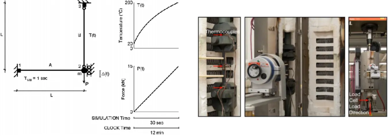
A third method is hybrid simulation, which has been widely used in seismic field, inspired from substructuring methodology. The idea of hybrid simulation is to combine the advantages of individual testing method and full scale testing, meaning that individual element(s) will be tested while accounting for the surrounding’s contribution. The surrounding can be modelled via nonlinear numerical software or a predetermined matrix (if elastic behavior of the surrounding is expected). The part of the structure tested in the furnace will be referred to as the physical substructure (PS), while the surrounding as the numerical substructure (NS). The method then consists in ensuring equilibrium and compatibility between these two substructures over the duration of the test. At each time step, data (displacements or forces) are measured at the substructure interfaces. Due to the fire exposure of the PS, equilibrium and compatibility at the interface are not generally satisfied any more at the end of the time step. To restore the equilibrium and compatibility at the interface, new data are computed (forces or displacements) and are imposed to the substructures, based on the measured data from the previous time step. At frequent intervals (time step Δt), the displacements or the forces at the interface are measured from the PS and this information is sent to the NS. The reactions (forces or displacements) of the NS at the interface are calculated and then sent back to the PS. There may be an additional delay of time Δt𝑃 requested for the calculation of the
NS reaction and for application of the reaction to the PS. The procedure is either called force control procedure (FCP) or displacement control procedure (DCP), when reaction forces or displacements are sent back to the PS.
10
The key components in hybrid simulation will be next presented more in detail and the procedure will be described. Using the hybrid simulation, a variety of advantages is gained compared with the individual testing method and the full scale method. In addition, several types of challenges need to be addressed. The advantages and challenges when using hybrid simulations will be discussed. While in seismic field the method is widely studied, in fire field only few tests have been performed using hybrid methodology. The direct implementation of the method used in the seismic field to the fire field is not possible due to the fact that there are some obvious differences between the fields. The difference between the hybrid testing in seismic field and hybrid fire testing will be discussed together with the numerical and experimental errors which can affect the accuracy of the method. In the last chapters, the history of hybrid simulation and the state of the art in fire field is presented.
2.2. Components and procedure
To perform a hybrid simulation, there are several components which need to be controlled and interact during the test. The objective of the hybrid simulation is to analyze the behavior of a structural system by combining the experimental testing and the numerical analysis of the remainder. The interaction between the two parts should be ensured during the test in order to achieve equilibrium and compatibility at the interface. To do so, the key components needed in this process are next described and presented in Figure 2-1.
1. The physical substructure (PS) to be tested in a furnace is the key component of hybrid fire testing. The PS is the part of the structure which will be experimentally tested in the furnace. The choice of the PS will be done based on the following criteria: (i) unknown behavior of a new material or (ii) a new structural system difficult to be represented numerically.
2. The second key component is represented by the numerical substructure (NS) to be analyzed aside during the hybrid simulation. The NS can be modelled in a finite element (FE) model or it can be predetermined in a matrix. There are some differences in the hybrid simulation process depending on how it will be chosen to represent the NS.
The FE model is recommended when parts of the NS are exposed to fire. The drawback of representing the NS by FE software is the time needed for every time-step calculation during the interaction. In hybrid fire testing the time of the calculation needs to be short in order to be able to reach equilibrium and compatibility at every interaction time step. The advantage of the method is the possibility of considering parts of the NS exposed to fire too.
When the NS remains cold during the hybrid simulation, then the behavior of the NS can be accounted for by using the predetermined matrix. This means that a matrix will be defined before the hybrid simulation; therefore the calculation time of the NS is virtually zero. Predetermined matrix accounts for the stiffness of the NS, the load pattern and the condensation of DoFs at the interface.
To reduce the time needed for one-step interaction in hybrid simulation the predetermined matrix is recommended to be used when possible.
HYBRID SIMULATION FUNDAMENTALS
11
Physical Substructure PS Data-Acquisition System
Transfer System Numerical Substructure NS
Figure 2-1. Components of hybrid fire testing
Structural system to be analyzed
Beam (PS) inside the furnace
12
3. The transfer system between the NS and PS;
The transfer system means the actuators needed to apply the time step response (displacements in displacement control procedure and forces in force control procedure)
4. The data acquisition system in the furnace;
The data-acquisition system refers to the instruments employed during the hybrid process in order to read the data from experimental process. Examples of such instruments are (i) the displacements transducers and inclinometers and (ii) load cells. The displacements transducers and the inclinometers are used to measure the evolution of displacements and rotations in time, while the loads cells have the properties to read the reaction forces (or restoring forces) in the actuators.
The procedure of hybrid fire testing is next described.
Hybrid fire testing can be performed in force control procedure (FCP) or displacement control procedure (DCP). The steps to be followed during the hybrid fire testing HFT as presented in the literature are described right below.
Step 1: Before starting the hybrid fire testing, the interface forces and displacements need to be determined for ambient conditions. To do so, analyze the entire structure (with the physical substructure included in the analysis) at ambient temperature under the loading relevant to the fire situation (called here “external loads”) and obtain the corresponding effects of actions called here the reaction forces (bending moments, axial forces, shear forces, torsion moments) and displacements/rotations at the interface between the physical substructure and the numerical one.
Step 2: Run another analysis for the numerical substructure, but this time without the physical substructure, when the numerical substructure is subjected to the external loads and, at the interface, to the reaction forces (DCP)/displacements (FCP) resulted in Step1.
Step 3: For the physical substructure in the furnace, apply the initial forces or displacements at the interface obtained from step 1 and the external loads which are applied to the physical substructure. The fire test is now ready to start.
Note that when the physical specimen is loaded before starting the fire, it may be possible to get a different value of interface displacements (FCP)/reaction forces (DCP) than the ones calculated in the Step 1. In this situation some additional calculations are needed to restore the interface equilibrium and compatibility at ambient temperature, before the start of the fire. Section 5.2.3 presents more details about this activity.
Step 4: Turn the furnace on.
Step 5: Read the variation of reaction forces (DCP)/displacements (FCP) of the heated physical substructure at the interface after one time increment.
HYBRID SIMULATION FUNDAMENTALS
13
Step 6: From the situation obtained after step 3, impose this variation of reaction forces (DCP)/displacements (FCP) to the numerical substructure and calculate the effects of actions at the interface, displacements (DCP)/reaction forces (FCP). Note that using the finite element analysis, part of the NS can be exposed to fire too.
Step 7: Adjust the displacements (DCP)/reaction forces (FCP) forces applied to the interface of the physical substructure in the furnace. The time needed to perform the calculation of the NS and to apply the new corrections in the furnace will be referred to as the delay time ∆𝑡𝑃.
Step 8: Repeat Steps 5 to 7 for each time increment ∆𝑡, for the entire period of the test including the cooling phase if relevant.
After Step 7 the equilibrium and compatibility at the interface need to be ensured. Due to the fire exposure, while performing the calculation of the NS, the interface conditions are changing. Therefore, at the end of the Step 7 there is a risk not to satisfy the compatibility and equilibrium conditions if the calculation time is too big.
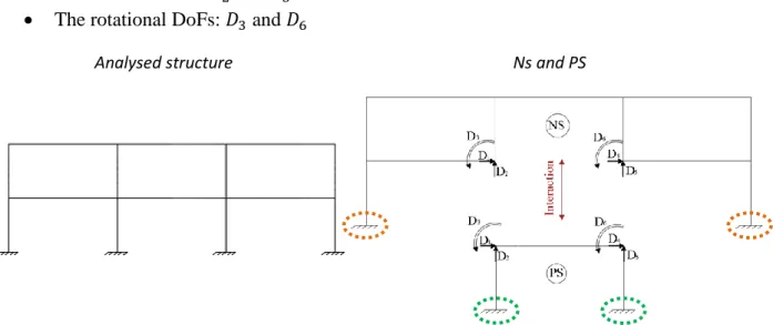
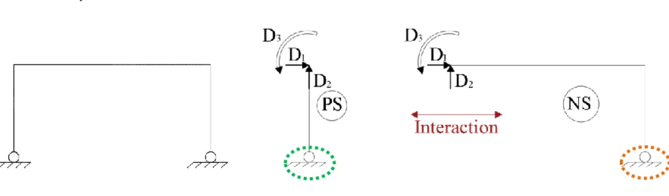
When the structure to be analyzed is divided in the PS and NS, the number of degrees-of-freedom (DoFs) at the interface is 𝑛𝑡𝐷𝑜𝐹. When PS is placed in the furnace the rigid body modes need to be suppressed, resulting 𝑛𝐷𝑜𝐹 at the interface. This means that the total number of DoFs 𝑛𝑡𝐷𝑜𝐹 at the interface is reduced [6] in the number of DoFs which can be controlled in the furnace 𝑛𝐷𝑜𝐹. By using a predetermined matrix to represent the NS, the condensation of DoFs is already implemented in the matrix and no additional calculations are needed. When the finite element analysis is used in the hybrid simulation, then the condensation of DoFs needs to be done during the test. More details about the condensation of DoFs will be presented in the chapter 3.3.
2.3. Advantages and challenges
Hybrid simulation technique combines the analytical and the experimental approaches to investigate the behavior of the structural system.
The most important advantages are summarized here bellow:
Hybrid simulation consist in subdividing a structure in two substructures (i) the NS characterized by a well understood behavior reliably modelled in finite element models and (ii) the PS characterized by the fact that is difficult to be modelled numerically and is thus obtained from a physical test in a laboratory. The uncertainties will be reduced if the numerical model of the unreliable parts is replaced with actual physical components.
Experimental and numerical models can take advantage of the different capabilities available in different laboratories using geographically distributed hybrid simulation.
The global behavior of structures can be reproduced only by means of hybrid fire testing. This method presents the advantage of providing the real failure time during the fire exposure and the real failure mode.
14
The hybrid simulation method presents advantages compared with the other existing methods, but several challenges still need to be addressed by conducting further research in this field. The challenges of using hybrid simulation are presented next:
During the hybrid simulation, data are measured and imposed on the PS every time step. The acquisition and transfer system (actuators and transducers) used to control the interface data (displacements/reaction forces) should be suitable for different types of configurations.
Each implementation of hybrid fire testing done so far is dependent on the testing site and control, and on the data –acquisition system. The software framework is difficult to be adapted to different structural problems and even to different laboratories.
The need of a common software framework for developing and performing hybrid simulation. The object-oriented software framework should be robust, transparent, easily extensible and environment independent.
Using hybrid fire testing, there are different sources of errors which can affect the accuracy of the results: (a) modelling errors (e.g. discretization process); (b) experimental errors generated by the control and transfer system; (c) experimental errors introduced by the instrumentation devices; and (d) unappropriated method of performing hybrid simulations. All these errors can lead to instability during the test.
Depending on the stiffness of the structures, tests with stiff physical substructure can be difficult to execute under displacement control. One solution to stiff structure would be to use a force control procedure. This means that the method should be suitable for this specific problem and other specific problems which can be identified.
If the future geographically distributed hybrid simulation can be used, then the networks delays and breakdowns should be avoided and the communication speed needs to be improved as much as possible. A delay in communication can have a crucial effect on the results, due to the fact that during this time the fire exposure continues in the furnace.
2.4. Seismic vs. Hybrid Fire Testing
Some differences between the two fields when performing hybrid simulations will be presented in the Table 2-1 to highlight the impossibility of implementing the methods from seismic field directly to the fire field.
The first difference between the two fields is the equation that needs to be solved during the hybrid simulation. For the seismic field a dynamic equation governs the procedure while in the fire field the static equation needs to be solved. When the PS is exposed to fire the expansion develops slowly in time. Therefore, there is no need of a dynamic approach.
The static approach is characterized by the fact that the stiffness of the PS is used in the calculations and this represents a challenge considering that it is not easy to determine the stiffness of the PS. Due to the fire exposure, this value changes during the duration of the test and the change can be significant close to the failure. For floating subdomains (which experience rigid body movements) additional calculations need to be done to find the invert of the singular stiffness matrix. In seismic field, depending on the type of the considered solver, the evolution of the stiffness matrix during the test is not always requested.
HYBRID SIMULATION FUNDAMENTALS
15
One of the main challenges of hybrid fire testing is related to the necessity to conduct the HFT in real time; except for metallic elements in which a uniform temperature distribution can develop, the temperature distribution in most elements is highly non-uniform and time dependent and cannot be scaled down in time (this is particularly significant for concrete or timber elements). In seismic field, reduced scale tests are possible (similitude theory is needed in this case).
Real time testing is needed in fire field compared to seismic field, where slow tests, rapid tests, real time tests and smart shaking table tests are possible. In fire field, except for some specific elements, i.e. pure metallic unprotected structures, the evolution of the thermal gradient in the section of the PS continues even if the fire stops. This requests a real time testing and a fast interaction between the substructures during the hybrid simulation. In seismic field, the slow tests can be executed on extended time-scales of up to two orders of magnitude slower than the actual time-scale. To avoid force relaxation and actuator stick-slip difficulties, rapid tests have been implemented, where the inertial and viscous damping forces are generated in the physical substructures. Another alternative is to perform the hybrid simulation in real time or to execute smart shaking table tests. For every case, the algorithms to solve the dynamic equation are specific.
In fire fields, the structural elements are tested in furnaces, exposed to different fire load. This means that the structural elements need to be assembled (positioned) in such a way to build a closed space where the load fire can be reproduced properly. The structural elements can be totally or partially exposed to fire. The transfer system and data-acquisition system must be protected from the fire exposure (placed outsides the furnace) whereas in seismic field no protection is needed since the test is performed at ambient temperature.
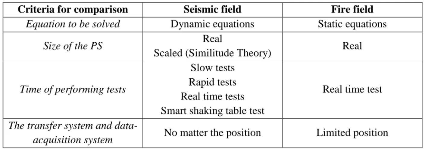
Table 2-1 summarizes the differences between the seismic and fire hybrid testing.
Table 2-1. Hybrid simulation in seismic versus fire field
Criteria for comparison Seismic field Fire field
Equation to be solved Dynamic equations Static equations
Size of the PS Real
Scaled (Similitude Theory) Real
Time of performing tests
Slow tests Rapid tests Real time tests Smart shaking table test
Real time test
The transfer system and
data-acquisition system No matter the position Limited position
2.5. Numerical and experimental errors
In hybrid simulation process errors can be introduced into solution at different stages. A first classification of the errors is the numerical errors versus experimental errors.
16
Since the fire exposure is continuous, the time needed to perform the calculation of the NS when using the finite element model and to apply the new values on the PS is a factor of error. While the calculation of the NS is undergoing the PS is still exposed to fire. This means that the interface data (reaction forces (DCP)/displacements (FCP)) from the calculations time step are different compared with the interface data (reaction forces (DCP)/displacements (FCP)) from the time when the data are imposed on the PS. Therefore the interface equilibrium and compatibility are not satisfied. The influence of the time calculation and the time needed to induce the target values on the PS needs to be carefully studied.
The methodology used to perform the hybrid fire testing is another factor of errors. The applied method needs to be stable, to ensure equilibrium and compatibility and to be able to reproduce the global behavior. More information about the instability induced by the wrong methodology will be presented more in detail in the chapter 4.
Other source of errors can be generated by the transfer system which imposes the calculated response quantities on the PS. The transfer system needs to be tuned correctly in order to avoid the poor results.
Experimental errors are the most common errors when experimental tests are performed. For example the resolution of the instrumentation, the noise generated in the instrumentation and the calibration errors can produce inaccurate or incorrect measurements leading to poor test results.
More research needs to be done in this area to observe the influence of different errors on the results.
2.6. History of hybrid testing in the seismic field
In this section, a brief history of hybrid methodology within the years will be presented. Searching for new methods to evaluate the dynamic behavior of structures, especially the seismic performance of large-scale structures, the hybrid simulation testing technique started to be developed in the early 1970s, but it was first published in 1975.
There are several methods for evaluating the seismic behavior of a structural system: quasi-static testing method, shaking table tests and hybrid simulation method.
The quasi-static tests are relatively easy and economical. The methodology consists in applying a predefined history of loads or displacements on the tested specimen. The advantage of the method is that the changes in the materials, the boundary conditions and other factors can be identified imposing the same loading on different series of specimens. But the load pattern does not model the change of the load distribution that a structure experiences during a real seismic event.
Shaking table tests are able to simulate the close conditions that would exist during a particular earthquake. The advantage of this method is that the dynamic response of a structure can be analyzed considering specific ground motion, the inertial and energy-dissipation characteristics of the tested structure. Most of the shaking tables are limited in size and capacity, so there is a need to implement dynamic similitude.
![Figure 2-5. The configuration of the considered structure (excerpt from Robert [64]) Step 2: The configuration of the PS is establish](https://thumb-eu.123doks.com/thumbv2/123doknet/6657169.182086/45.892.204.702.188.495/figure-configuration-considered-structure-excerpt-robert-configuration-establish.webp)
![Figure 2-6. The set-up of the PS (excerpt from Robert [64]) Step 3: The start of the fire and the implementation of hybrid simulation](https://thumb-eu.123doks.com/thumbv2/123doknet/6657169.182086/46.892.134.782.129.559/figure-excerpt-robert-step-start-implementation-hybrid-simulation.webp)
![Figure 2-8. The configuration of the structural system used by Mostafaei (excerpt from Mostafaei [66])](https://thumb-eu.123doks.com/thumbv2/123doknet/6657169.182086/47.892.108.772.612.825/figure-configuration-structural-used-mostafaei-excerpt-mostafaei.webp)
![Figure 2-10. Axial load versus the axial displacement during the hybrid fire tests presented by Mostafaei (excerpt from Mostafaei [66])](https://thumb-eu.123doks.com/thumbv2/123doknet/6657169.182086/49.892.111.783.390.581/figure-axial-versus-displacement-presented-mostafaei-excerpt-mostafaei.webp)