Science Arts & Métiers (SAM)
is an open access repository that collects the work of Arts et Métiers Institute of
Technology researchers and makes it freely available over the web where possible.
This is an author-deposited version published in:
https://sam.ensam.eu
Handle ID: .
http://hdl.handle.net/10985/12037
To cite this version :
Romain DUBALLET, Olivier BAVEREL, Justin DIRRENBERGER - Classification of building
systems for concrete 3D printing - Automation in Construction - Vol. 83, p.247-258 - 2017
Any correspondence concerning this service should be sent to the repository
Administrator :
[email protected]
Classi
fication of building systems for concrete 3D printing
R. Duballet
a,c,⁎, O. Baverel
a, J. Dirrenberger
b,ca Laboratoire Navier, UMR 8205, Ecole des Ponts, IFSTTAR, CNRS, UPE, Champs-sur-Marne, France b Laboratoire PIMM, Ensam, CNRS, Cnam, Hesam Université, 151 bd de l’Hôpital, Paris 75013, France c XtreeE, 18/20, rue du Jura, Rungis Cedex CP 40502 94623, France
A R T I C L E I N F O
Keywords: 3D printing Robotic complexity Construction Concrete Additive manufacturingA B S T R A C T
In the present paper, a study is conducted on building systems associated with concrete extrusion-based additive manufacturing techniques. Specific parameters are highlighted - concerning scale, environment, support, and assembly strategies - and a classification method is introduced. The objective is to explicitly characterise con-struction systems based on such printing processes. A cartography of the different approaches and subsequent robotic complexity is proposed. The state of the art gathered from the literature is mapped thanks to this classification. It appears that the disruption potential brought by concrete 3D printing has not been fully em-braced yet.
1. Introduction
1.1. Printing processes and building systems
There has been a growing interest upon additive processes for civil engineering over the past two decades. Pegna [1]proposed freeform construction as a newfield of investigation. Since then, several additive manufacturing processes have been explored for large-scale application: B. Khoshnevis's Contour Crafting [2]and Loughborough University's Concrete Printing[2–4]rely on pumping and extruding cement-based paste to create 2.5 D structures that are to be included in a larger building system. More recently, some of the co-authors of the paper have developed a novel concrete printing process featuring six axis robot control that allow full 3D elements to be manufactured without the help of temporary support[5]. The present work is a collaboration between Laboratoire PIMM and Laboratoire Navier, which is known for its research on complex structures[6–8]
Such processes have mostly been investigated in terms of ro-botics[9], rheology[10]and material mechanics[5,11-15]. The pro-blem of actual implementation in the building industry has not been fully addressed. Two main applications of such technologies can be drawn from the literature. The first one, already mentioned in [2], consists in“printing” a whole building directly on site by extruding two layered mortar form works for the walls. Additional robotic devices take care of bringing reinforcement bars and other non-concrete ele-ments needed for the building. Another family of building systems, implied in other works do not aim for on-site printing, but use the in-novative process to manufacture more valuable building components,
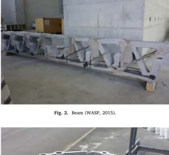
that are to be put together during the construction phase. This is the case for Loughborough's Wonder Bench, that“includes 12 voids that minimise weight, and could be utilised as acoustic structure, thermal insulation, and/or path for other building services” [3], and for DE-MOCRITE project multifunctional wall, that works as a form-work the internal 3-D sinusoidal shell reinforcement structure of which allows a great reduction of thermal conductivity[5].
If the innovative potential of such approaches is difficult to dispute, it remains unclear (1) how exactly such a printing process should effi-ciently and usefully be implemented in a construction workflow, and (2) given a printing process, what are the attainable“forms” ? In fact, as stated in Gosselin et al.[5], the concept of free form seems insufficient
to thoroughly describe large scale additive manufacturing. Depending on the chosen process, one can print a specific family of geometries, topologies, in a given time and reach a certain performance for the structure. In addition, the way such a process is invested in a whole framework of design, analysis, manufacturing and building up, will have a crucial impact on the pertinence of the approach. It seems im-portant to distinguish the “printing process” from the “building system”. The former denotes the set of devices (robot, pump, etc.) needed to shape the material, while the second one refers to the whole construction method, from raw material to the final building. To a given printing process can correspond several building systems. A sys-tematic characterisation of the later, in a sufficiently explicit and ex-haustive way, is currently missing in thefield of large-scale additive manufacturing applied to construction.
In this paper we propose a classification of such building systems. Several key parameters are highlighted, concerning either the printing
⁎Corresponding author at: Laboratoire Navier, UMR 8205, Ecole des Ponts, IFSTTAR, CNRS, UPE, Champs-sur-Marne, France.
E-mail address:[email protected](R. Duballet).
itself or its context of use. At stake is a way of comparing diverse procedures to each other, and a mapping of possible approaches. We first introduce a notation system, and investigate the relation between some proposed parameters. Then, a study on robotic complexity is conducted, since it appears to be an important parameter to dis-criminate between several possibilities. The statements and conclusions made here are open for discussion, as the paper deals with very recent technologies, and because it is not yet clear how the building industry will be transformed by them. Yet, we believe such a way of char-acterising those new methods sheds light on what remained unclear thus far.
1.2. Variation of parameters:first approach
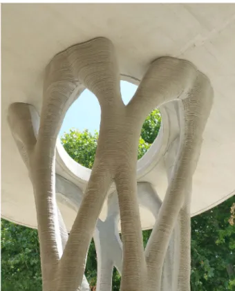
On thefigures below are depicted three different ways of making use of a similar concrete printing process (similar in their objectives, if not in their actual results), which leads to three very different ap-proaches in terms of building systems. OnFig. 1is a prototype of a “flat” wall that have been horizontally printed on the floor and then moved to its vertical position. Such a strategy allows great geometrical freedom for thin 2.5 D structures, as it takes advantage of the smallest dimension of the object and gets rid of the main difficulty of a direct printing: height. However, from a structural design perspective, the loading that corresponds to the handling of the object is likely to be the worse case scenario, and therefore to spoil the attainable lightness of the wall. Fig. 2 depicts an interesting idea proposed by the WASP Project1which consists in assembling adequately designed components, mixed with steel bars, to form an ultra-light composite beam.Figs. 3 and 4show a viable way of printing a concrete mould that is to befilled with UHPFC2. The unused parts between the tubes are removed after-wards keeping only a very light tubular space-truss structure, here a load-bearing pillar. Those three examples of what is called“indirect” printing reveals that more possibilities are offered by concrete printing. The aim of present work is to explicitly characterise the set of possible building systems using concrete printing, and the subsequent associated robotic complexity. Many parameters can be considered due to the complexity of such processes. One of them, which is from the traditional 3D-printing industry, can be the printing support. It is well known that one can print an additional material, called support mate-rial, in order to reach specific geometries. This support is to be removed in a subsequent step. At large scale, however, the pertinence of such an approach needs to be compared with the use of external supports like falseworks. Theflat wall example onFig. 1can be seen as the use of a “flat” support, whereas the example onFigs. 3 and 4makes use of no external support (but removable concrete parts can be considered as printed support). This can be generalised by listing the families of possible external supports, as depicted inFig. 5. With the exact same printing process, i.e. mortar extrusion, controlled with a 6-axis robot, and varying only the type of external support, one obtains very different building systems, and diverse attainable forms. This analysis highlights the need for additional considerations, for instance regarding assembly. Indeed, if direct printing without external support can be done without bringing any external part, or assembling elements, a multiple printing necessarily entails an assembly step. Likewise, a collaborative printing, where external supports are brought during the extrusion step can be considered as including an assembly step. Pointing out these differences between building systems is critical to correctly anticipate the asso-ciated complexity, technological barriers and to estimate the cost of a project. In addition, a given constructive result can be obtained by cleverly getting around an obstacle - working on the building system as a whole, preferably than developing overly complicated processes which will struggle to achieve industrial implementation.
2. Classification 2.1. Key assumptions
Following the previous intuitive considerations on the qualification of concrete printing building systems, the problem reveals itself as a parametrisation matter. In this work, we introduce a notation system, based on the most critical parameters to consider, and an example of using such notation in order to compare building systems in terms of robotic complexity. Since a parametrisation needs to be as concise and exhaustive as possible, we reduce our problem based on the following hypotheses.
Fig. 1. Flat wall (Democrite project, 2015).
Fig. 2. Beam (WASP, 2015).
2.1.1. Cementitious paste extrusion
Our analysis is limited to processes engaging cementitious material extrusion, that is to say a system of shaping cementitious paste, mortar or concrete byflowing it out through a moving opening. Such processes include at least a mixing step, a transport step (pumping) and a shaping step. We include in this definition the recent 3D printing of concrete as well as contour-crafting method, but also the older technique of slipforming.This last approach has been recently renewed by Lloret et al.[16], at a smaller scale for shaping vertical building parts. This method was separated from layered extrusion processes by Wangler et al. [15], as those two printing processes are different in terms of materials science. Nevertheless, they can both be treated as cementi-tious extrusion techniques from the building systems viewpoint. The difference between layered extrusion and slipforming is treated here as a difference of “extrusion scale” (parameter xe, seeSection 2.2).
Ex-trusion scale for slipforming is usually around 1/10 of the printed ob-ject size, whereas this number is lower for layered extrusion processes (e.g. around 1/1000 for the example depicted onFigs. 3 and 4). Since we will be dealing with printed support material, it will not necessarily be extruded and/or cementitious (but could also include clay, polymer, or any useful material), however what is considered to be the“main”
printed material has to engage cement. Our analysis is limited to ex-trusion processes, hence excluding other additive manufacturing tech-niques like stereo-lithography or powder bed-based printing (e.g., D-shape, or more recently Emerging Objects). Yet, the proposed system of notation remains open for generalisation, and because some of these AM techniques have recently been proposed at large-scale, it would be useful to conduct a similar investigation.
2.1.2. Extrusion speed
One of the critical aspects of concrete 3D-printing is the extrusion speed, more precisely the speed of the nozzle shaping the paste. Since this quantity is directly linked to the printed concrete behaviour, our previous experiences have shown it to be scale-dependent[5]. As a matter of fact, if a large quantity of concrete is being extruded, e.g. by slipforming, the only way to get it chemically and mechanically sound will be to give enough time for the setting to happen. That is why such techniques traditionally exhibits slow“nozzle” speeds, typically around a few meters per day. On the contrary, when extruding mortar laces around 1 mm, it is preferable to keep a relatively high-flow pumping system while increasing the nozzle speed, up to several hundreds of millimetres per second. The main reason for it being that such precise printing must be as quick as possible to be implemented in the building industry. Therefore we have chosen not to take the nozzle speed as a parameter in this paper, but rather to consider an extrusion scale parameter, which is directly related to the nozzle speed under the present assumptions, and more pertinent to characterise building sys-tems in terms of precision. In this context, if one would want to use a relevant speed parameter, it would have to be taken from the whole building system, and not limited to the extrusion step.
2.1.3. Maximum automation: limited human intervention
The technologies of interest in this paper take part in the global movement toward automation. Hence, we suppose that any human intervention in the framework is limited to handling or gathering few, simple, small elements. When robotic speeds are high enough, no human interaction is planned for security reasons.
2.1.4. Robotic system
The shaping step is conducted by a robotic system, going from gantry cranes to more complex robots, such as 6-axis. If the nozzle itself can in-clude robotics, like smoothing or cutting devices, it is considered as a secondary system, while the device moving the nozzle is called primary. A third robotic system can intervene after printing, for instance to handle large or special printed elements. Only if such actions are taken during printing phase, this system is included in the primary one.
2.2. Notation
A given set of building systems is denoted by enumerating the parameters it is concerned with
Fig. 4. Printed pillar in Aix-en-Provence (XtreeE, 2016).
…
x x e a son
em i j k (1)
where pnstands for the nth version of parameter p. The parameters are
indeed divided into categories, explained below. The two parameters xo
and xeare scale parameters, respectively about the printed object and
the extrusion, while the parameters e, a, and s respectively concern printing environment, assembly and support. The notation is not length-constrained, for instance the set e0 includes every building system consisting in on-site printing, while the sub-set e0s0corresponds
to all on-site building systems making use of no support for the printing. We detail below the numbered versions of theses main parameters. The division made here, as well as the indicative values of parameters, are gathered from the literature and the own experience of the authors, while being subject to change.
2.2.1. Object scale xo
This is one of the main parameters to take into account, for it will strongly orient the decisions taken about a system. It deals with the size of what is printed. We divide it in four versions.
xo0(dm) - Printed object of size less than a meter, typically a
con-nection.
xo1 (m) - Constructive element of size around 1–4 m, typically a beam, column or slab.
xo2(dam) - Object around 5–10 m, typically a living unit or a house.
xo3(dam) - Full tall building.
2.2.2. Extrusion scale xe
This parameter is a characteristic size of what is extruded. Depending on the process it can be a nozzle diameter, a mortar lace section, or thefinal thickness of a printed layer. Again it is divided in four scales, taken from literature and our experience to correspond to four diverse material behaviours.
xe0(mm) - e.g. a thickness layer less than 8 mm
xe1(cm) - e.g. a thickness layer between 8 mm and 5 cm xe2(dm) - e.g. a thickness layer between 5 cm and 30 cm xe3(m) - e.g. a thickness layer above 30 cm
2.2.3. Environment e
We have extracted three possibilities concerning printing environ-ment. The first one e0 corresponds to a direct printing on-site and
without any additional handling of the object. The second one e1refers
to a printing done in a controlled environment (temperature, hygro-metry,…) thanks to a light/mobile structure deployed on construction site. The last one e2is a traditional prefab factory, imposing handling
and transport of the printed object. e0On-site (direct printing)
e1Mini factory (indirect) e2Prefab factory (indirect)
2.2.4. Assembly a
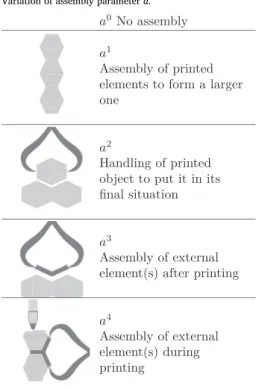
As seen above, a building system using concrete printing can include some assembly step. We define this term as the action of bringing a macroscopic element by an external device, either during or after printing. This means we do not consider falsework as an assembly step (but as a support, see below). The term“macroscopic element” is op-posed to“inclusions” that can be mixed to the extruded mortar, like polystyrene beads orfibres. In that specific case we consider that the secondary robotic device (printing head) is in charge and do not treat it as an assembly step. The assembly step is conducted either by human workers or a third robotic device. There are four types of assembly in our classification, summed up inTable 1.
The majority of the above possibilities are not contradictory with the others, that is why a building system can exhibit several of them, for example the prefab of a multifunctional wall with window, electricity and plumbing could be denoted by e2a2a4. Only the parameter a0, which cancels out the other ai parameters must remain by itself.
Furthermore, an a1system necessarily implies an additional handling
a2. The legit combinations are summed up in the diagram onFig. 6.
2.2.5. Support s
Likewise, we have extracted four categories of supports. By this term we mean every rigid (or semi-rigid) surface on which is deposited the extruded material and that has a beneficial effect on its stability. As we oppose this term to“assembly”, a support is supposed to be brought either before or during printing. A printing is called“without support”, and denoted by s0when no other surface than ground or foundations serves the printing. The combinations between different versions of the parameter s are simpler than with parameter a for there is only the cancellation of s0to take into account (seeFig. 7). Two aspects are
addressed here: if the support is printed or brought by an external de-vice, and if it is to remain after the printing or not. SeeTable 2. 2.2.6. Robotic complexity r
In addition to thisfive main parameters, it is also useful to point out the robotic complexity engaged in a certain building system, for it will decide of its feasibility, its cost and the amount of research needed before it can be implemented at an industrial scale. Today, most of the
Table 1
Variation of assembly parameter a.
research engaged in concrete printing makes use of 3-axis robotics, technological research being preferably oriented upon secondary de-vices that brings external elements to a directly printed building. Some works have made use of 6-axis robots, and few of them have experi-mented the potential of this new complexity. The following list is a version of what would or will be explored as new robotic complexity in the near future, we will make use of this parameter r in the next section.
r0One 3-axis robot
r1One 6-axis robot
r2One 6-axis robot with an axis at his base (rail) r3Two 6-axis robots (collaborating)
r4Two 6-axis robots with an additional axis at their base
r5One 6-axis robot on a 3-axis robot r6Two 6-axis robots on two 3-axis robots
2.3. Examples
The three examples shown on the first 3 figures can be given a combination of these parameters:
- Theflat wall onFig. 1corresponds to the combination x x e a so e1 1 2 2 4.
- The beam onFig. 2can be denoted by x x e a a so e1 1 2 2 3 4.
- The pillar and its mould on Figs. 4 and 3 is a x x e a a a so e1 0 2 1 2 3 2
ap-proach.
2.4. Scale variations of parameters e, a, and s
The different versions of these parameters are not independent from each other. In this subsection, we explore the relations between the two scale parameters (the sets x xoi
ej), as well as their link with each main
parameter (the setsx x eoi ej k,x x aoi ej kandx x soi ej k). More precisely we want
to switch off the impossible, or trivially bad, combinations. Table 3
sums up this information.
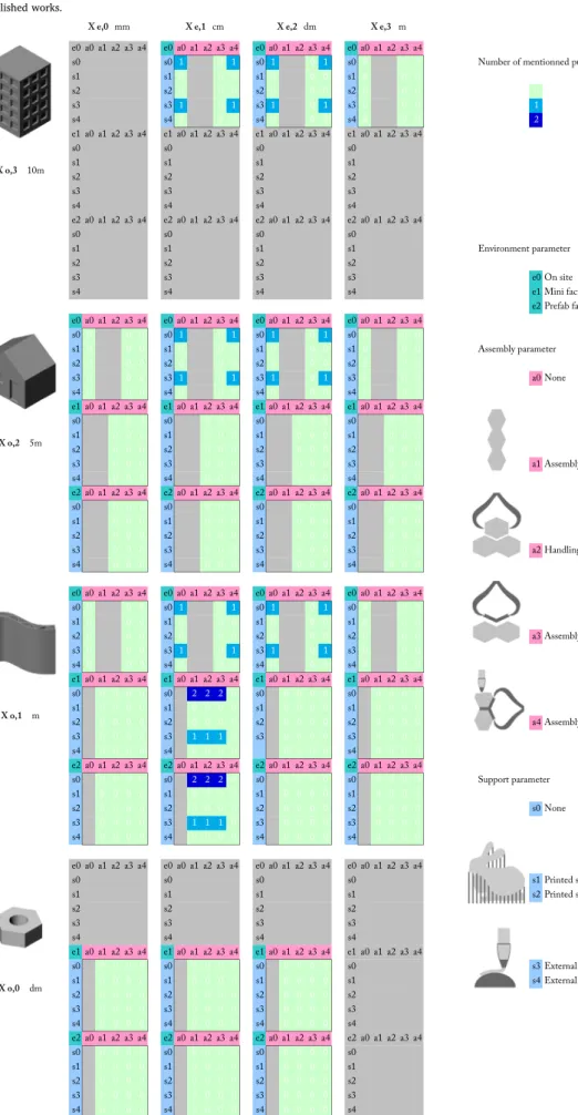
The sixteen squares corresponds to eachx xoi ej combinations. Three
of them are fully gray-coloured, because they make no sense: for in-stance x xo0 e2,3means printing an object smaller than the extrusion size,
while x xo3 e0does not seem to be a clever choice for precision.
Inside the sixteen squares are three coloured lines, each part of which corresponds to a combination x x poi ej k, where p = e,a,s is a main
parameter. Some versions of those are to be removed, as for instance
x eo3 1,2for it is advisable to use direct printing for a whole tall building.
Symmetrically, one would not print directly in place a connection to be assembled, that is why combinations of typex eo0 0are switched off as well.
Concerning assembly parameter a, it vanishes when objects are too big: no handling of printed elements when dealing with a tall building, the combinations of form x ao3 1,2are cancelled. As for the familyxo2of
few meter tall modules, one can imagine prefabricating them, but any handling would certainly mean putting them in place, and not form a bigger element to move again once assembled. In consequence only
x ao2 1combinations vanish. Finally as stated above, a connection is to be
assembled, so the combinationsx ao0 0never happens.
3. Variation of ther parameter
Once the scale variation of the main parameters is set, one can ex-plore their relationship to each other, at each scale. In this section, we explore combinations of type x x e a son em i j k, in order to understand which
of them cancel each other, and to try to synthetise their effect into a parameter of robotic complexity:
→
x x e a son em i j k rt (2)
The combinations of parameter s (i.e. the sets s1s3, s1s4, s2s3, and s2s4) are not mentioned in the table for the sake of clarity. For such
combinations sisjthe complexity r is supposed to be the maximal value
of complexities associated with each si.
3.1. Impossible eas combinations
InTable 4 are shown the possible and impossible combinations between the main parameters. The gray squares are inherited from
Table 3. Then, an incompatibility between parameters e and a can be observed at every scale: a direct, on-site, printing is incompatible with the assembly of previously printed objects, in that case they would be treated as external objects, not concerned by the printing in question. Likewise, any indirect printing needs assembly, so it cannot be com-bined with a0. Therefore we have the following implications:
⇒ >
a1,2 ( ;e ii 0) (3)
> ⇒ >
e i a j
( ;i 0) ( ;j 0) (4)
Other impossible combinations, emphasized with down-pointing arrows, are of type x e ao2 1,2 1as they correspond to the assembly of very
large printed elements to form an even larger structure, which seems absurd. Apart of those trivially wrong combinations, there is no obvious reason to dismiss more. In order to discriminate between building systems one needs to address an additional parameter: robotic com-plexity.
3.2. Parameter r
This parameter is intended to characterise a certain technological complexity associated with building systems. Considering the diversity of existing and future robotics, we cannot be too precise in indicating equipment specificities. Rather, we focus on the following 3 main points for robotic building: geometrical complexity, size, and collaboration. We clarify the different versions of parameter r below.
r0. One 3-axis robot
This corresponds to the robotics engaged in most concrete printing
Fig. 7. Possible combinations of support parameters.
Table 2
works today. It goes from little devices printing connections and small building elements to huge 3D printers able to build a whole house structure (mostly gantry cranes[2], and some cable robots[9]). The main advantages of such 3-axis devices is that they are already well developed and one can focus on secondary robotics devices like printing nozzles. However, they present a lot of limitations in the geometrical complexity of printable forms as well as in the possibility of multi ro-botics building systems.
r1. One 6-axis robot
With the use of 6-axis robots, the set of printable forms can be ex-tended, as explained in Gosselin et al.[5], for the layer can easily vary in their thickness and their orientation. It helps solving the problem of cantilevering printing structures and layer to layer adhesion. Colla-boration between robots, and between human and robots is more conceivable with 6-axis robotics, for they have multiple possible paths and orientations, which allows to address collisions problems. The main
drawback is that they are limited in size, at least for existing robotic arms.
r2. One 6-axis robot with an axis at its base (rail)
A way of increasing the printable size of a device is to put a 6-axes robot on a rail, possibly curved, so that it can turn around the element to print. This is an additional complexity for our classification.
r3. Two 6-axis robots (collaborating)
The next step for building system seems to be collaboration. Robots able to work with each other can bring great innovation to current building techniques, mixing printing and assembly, in a quick and precise fashion, inconceivable with current technologies. As far as our classification is concerned, parameter ri
with i > 2 means that no human take part to printing: the main advantage to robotic collabora-tion is speed, and it is incompatible with human workers security.
r4. Two 6-axis robots with an additional axis at their base
Table 3
Table 4
Table 5
Table 6 Mentioned works.
Table 7 Published works.
We increase the complexity parameter if the collaboration makes use of moving robots, to print large structures.
r5. One 6-axis robot on a 3-axis robot
This step represents an additional difficulty for robotics: to be able to maintain precision while moving a robot at large scale and in three dimensions. We include in this version of our parameter cable robotics that promise a lot of control from multiple axes, suspended on 6–8 cables, and lightness of large scale implementation[9].
r6. Two 6-axis robots on two 3-axis robots
This last version of parameter r corresponds to robotic collaboration with large scale implementation.
3.3. Linking main parameters to parameter r
As mentioned above we explore the relations between the process parameters, trying to link them to a minimal robotic complexity. The results appear inTable 5. It can be observed that complexity r increases with object scale xoand decreases with extrusion scale xe. However, if some versions of
parameters a and s yield complexity, it remains possible to perform large scale printing with a sole 3-axis device, denoted by r0, using light im-plementation like cable-structures. At such scale though, the challenge of bringing additional robotic axes rapidly increases complexity.
Concerning parameter s, it is supposed that the help provided by supports increases the number of attainable forms. A printing without support s0will be limited by the stacking of fresh concrete layers: slope,
holes, and cantilevers are difficult to obtain, and altering the material behaviour can penalize itsfinal properties. Printed support (s1, s2) solve
this problem byfilling some empty parts of the object with material. The simplest way of doing so is to use the same material (concrete) and either keep it or cut it out, or one can use an additional material, possibly easier to remove, like raw clay for instance. The printed sup-port strategies focus on printing nozzle development, so the complexity of the primary robotic system is not necessarily at stake. Conversely, the use of external support (s3, s4) takes advantage of an pre-existing
geo-metry to help the printing, that is why a greater need in robot move-ment variety can be assumed: six axis (r1) complexity is advisable at small scale, and its further versions (r2and r5) at larger scales.
Concerning assembly parameters a, the version a4is strongly related
to the complexity of the primary robotic device since it denotes as-sembly during printing. When extruding a very small mortar lace, the speed is far too high to allow human workers around, therefore the association x ae0 4 necessarily implies robotic collaboration (r3,r4,r6).
Likewise, when the object scale xoincreases. Furthermore, the
parti-cular sets a4s3,4denote the use of external supports assembled during
printing: the need for precision and robustness here leads to colla-boration as well, exception made for the scalesx xo e1 2,3where tolerance and speed are more easily handled.
4. State of the art
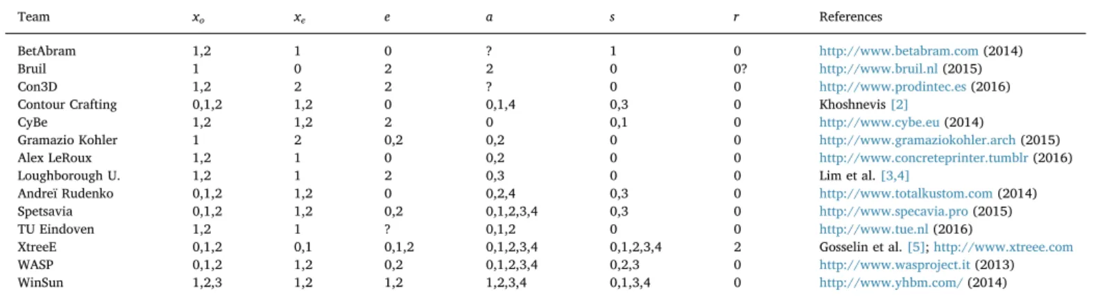
In this section, we compare existing works to each other using the proposed classification system. To do so, one cannot rely only on published and reviewed material, but needs to gather information on companies' websites and from non-scientific sources. The commercial and strategic aspects of each delivered piece of information about these new techniques make any verification difficult, and in all likelihood a lot of them are missing. This explains why we chose not to consider what is the actual technology used, but rather to focus on the state-ments themselves.
State of the art includes 13 contributions, with various approaches.
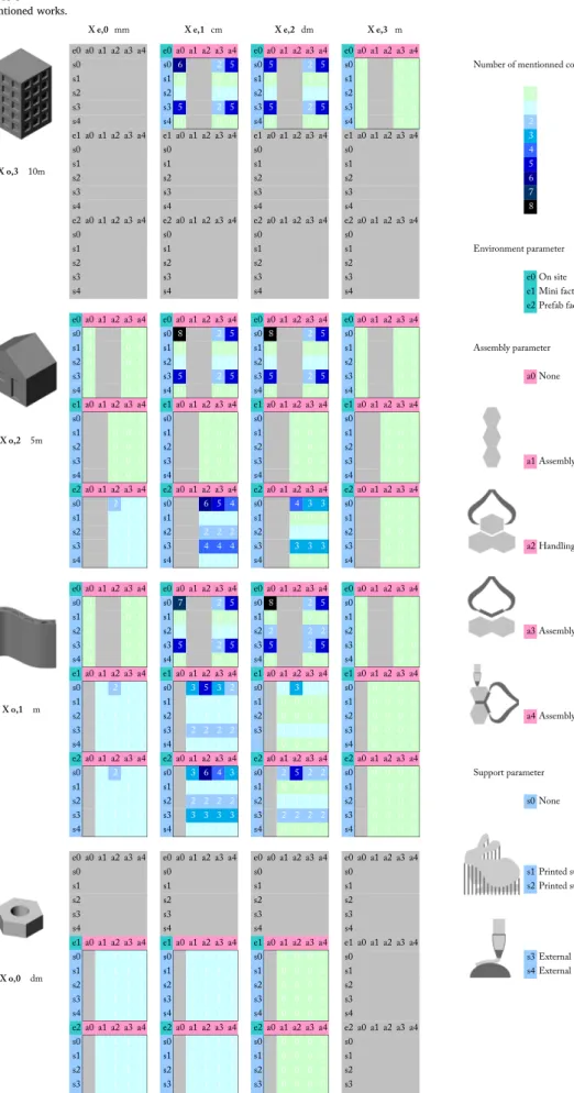
Table 8lists them and points out which version of the parameters are mentioned in the considered works.Table 6 presents the number of different contributions involved with each x x e a son em i j k combination,
based on mentioned approaches, whereas Table 7shows how many peer-reviewed papers corresponds to each combinations. The lack of academic and peer-reviewed contributions is visible, and very few has been published about alternative support and assembly strategies.
General observations can be made about current works according to these tables. Firstly, it appears that robotic complexity of primary printing device is not something that has been discussed until the present paper, the majority of works using only 3-axis devices. As far as we know, a study on non-planar and non-uniform extrusion shape thanks to 6-axis robotics can only be found in Gosselin et al.[5]. Sec-ondly, the majority of concrete printing teams work at a centimetric precision (xe1), and only two of them seem to go toward a few
milli-metres thick layers. In addition, there is no mention about large dia-meter extrusion systems (xe3) outside of existing slipforming techniques.
Finally, it also appears that complex building systems, as far as para-meters s and a are concerned, are not really addressed, although re-search about such strategies would most likely allow one to go around difficult obstacles raised by concrete 3D-printing (material behaviour, maximum printing height, total object size, and robotic path genera-tion).
5. Conclusion
This paper proposes an original way of classifying building systems relying on concrete 3D-printing. Five parameters are highlighted: object scale xo, extrusion scale xe, printing environment e, printing support s,
and assembly parameter a. Exploring the variations of these parameters and there combinations leads to an explicit mapping of possible building systems characteristics. Through this prism it can be clearly observed that concrete printing construction can exhibit much more variety than its current ambitions. The review of the state of the art shows that so far only a little part of the space of the possible solutions has been explored.
Table 8 State of the art.
Team xo xe e a s r References
BetAbram 1,2 1 0 ? 1 0 http://www.betabram.com(2014)
Bruil 1 0 2 2 0 0? http://www.bruil.nl(2015)
Con3D 1,2 2 2 ? 0 0 http://www.prodintec.es(2016)
Contour Crafting 0,1,2 1,2 0 0,1,4 0,3 0 Khoshnevis[2]
CyBe 1,2 1,2 2 0 0,1 0 http://www.cybe.eu(2014)
Gramazio Kohler 1 2 0,2 0,2 0 0 http://www.gramaziokohler.arch(2015)
Alex LeRoux 1,2 1 0 0,2 0 0 http://www.concreteprinter.tumblr(2016)
Loughborough U. 1,2 1 2 0,3 0 0 Lim et al.[3,4]
Andreï Rudenko 0,1,2 1,2 0 0,2,4 0,3 0 http://www.totalkustom.com(2014)
Spetsavia 0,1,2 1,2 0,2 0,1,2,3,4 0,3 0 http://www.specavia.pro(2015)
TU Eindoven 1,2 1 ? 0,1,2 0 0 http://www.tue.nl(2016)
XtreeE 0,1,2 0,1 0,1,2 0,1,2,3,4 0,1,2,3,4 2 Gosselin et al.[5];http://www.xtreee.com
WASP 0,1,2 1,2 0,2 0,1,2,3,4 0,2,3 0 http://www.wasproject.it(2013)
The key feature of this classification is to reinstate strategies other than the sole extrusion step into large-scale 3D-printing of concrete. In 1997, Joseph Pegna famously stated the concept of “solid free-form construction”, on which current approaches are based. According to Pegna, the additive manufacturing process has some potential in con-struction automation when“complex assemblies of large construction components are substituted with a large number of elemental compo-nent assemblies”[1]. It seems that this atomisation has been success-fully carried out from the material deposition process viewpoint, in replacing concrete pouring by mortar deposition, but it should concern the building system as a whole. In that sense one can distinguish an assembly step consisting in bringing a window to a contour crafted wall (x x e a so2 e1 0 3 0), from a collaborative printing where one additional robot
brings multiple complex parts to be used as support for the printing (x x e a so e1 1 2 4 3). The challenge is to create new complex building elements
of greater performances, and not only to speed up the building process. A good example of complex assembly strategy can be found in the space truss prototype made by EZCT Architecture and Design Research using the Voxeljet technology in 2013. This process does not involve concrete extrusion but the idea is indeed to“atomise” the assembly part: instead of building a complex mould as a whole, one defines a series of as-sembly rules to make it. Here 130 little sand mould halves have been printed and assembled to befilled with UHPFC (ultra-high performance fibred concrete). This approach makes no sense in a context of human labor, but become very relevant, in the sense of Pegna, for construction automation. The XtreeE pillar onFig. 4can be understood as a similar approach, but with concrete layer deposition and clever support strategy replacing sand printing and assembly.
To conclude, denoting building systems, as introduced in this paper, allows for explicit comparison of approaches that does not limit itself to a uniquefield of investigation. Indeed, several disciplines are engaged in this set of problems, such as rheology (of concrete), robotics (pre-cision, control, nozzle paths), and structural engineering, one could also add other civil engineering subjects like thermal and acoustic insula-tion, or environmental impact. It is of prime importance to generically address this complex problem without giving too much, or not enough, importance to a single aspect. It is not rare that a huge difficulty for one discipline simply disappears when confronted to another's agenda. This paper focuses on minimum robotic complexity to engage in each system. It helps understanding the technological and economical im-pact of the choice of a system, which ultimately discriminates between available solutions. Beginning such a classification will help clarify orientations toward new printing processes and building systems. Further work will, on one hand, refine, expand, and rely on this clas-sification, and on the other hand focus on the development of a
x x e a so e1 1 2 4 3system of collaborative printing.
Acknowledgments
The authors would like to thank V. Esnault and P-H. Jézéquel at
LafargeHolcim Research and Development for fruitful discussions. Support from LafargeHolcim is gratefully acknowledged.
References
[1] J. Pegna, Exploratory investigation of solid freeform construction, Autom. Constr. 5 (5) (1997) 427–437http://www.sciencedirect.com/science/article/pii/ S0926580596001665 http://dx.doi.org/10.1016/S0926-5805(96)00166-5ISSN 09265805.
[2] B. Khoshnevis, Automated construction by contour crafting - related robotics and information technologies, Autom. Constr. 13 (1) (2004) 5–19,http://dx.doi.org/10. 1016/j.autcon.2003.08.012ISSN 09265805.
[3] S. Lim, R. Buswell, T. Le, R. Wackrow, S. Austin, A. Gibb, T. Thorpe, Development of a viable concrete printing process, Proceedings of the 28th International Symposium on Automation and Robotics in Construction (ISARC2011), 2011, pp. 665–670, ,http://dx.doi.org/10.1080/0042311YYxxxxxxxxJanuary.
[4] S. Lim, R.A. Buswell, T.T. Le, S.A. Austin, A.G.F. Gibb, T. Thorpe, Developments in construction-scale additive manufacturing processes, Autom. Constr. 21 (1) (2012) 262–268,http://dx.doi.org/10.1016/j.autcon.2011.06.010ISSN 09265805. [5] C. Gosselin, R. Duballet, Ph. Roux, N. Gaudillière, J. Dirrenberger, Ph. Morel, Large-scale 3D printing of ultra-high performance concrete— a new processing route for architects and builders, Mater. Des. 100 (2016) 102–109http://www. sciencedirect.com/science/article/pii/S0264127516303811.
[6] L. Bouhaya, O. Baverel, J.F. Caron, Optimization of gridshell bar orientation using a simplified genetic approach, Struct. Multidiscip. Optim. 50 (5) (2014) 839–848,
http://dx.doi.org/10.1007/s00158-014-1088-9ISSN 16151488.
[7] C. Douthe, O. Baverel, Morphological and mechanical investigation of double-layer reciprocal structures, Nexus Network Journal 16 (1) (2014) 191–206,http:// dx.doi.org/10.1007/s00004-014-0185-9ISSN 15224600.
[8] S.S. Nabaei, O. Baverel, Y. Weinand, Form-finding of Interlaced Space Structures (Wccm Xi), (2014), pp. 1–12http://infoscience.epfl.ch/record/199001. [9] P. Bosscher, R.L. Williams, L.S. Bryson, D. Castro-Lacouture, Cable-suspended
robotic contour crafting system, Autom. Constr. 17 (1) (2007) 45–55,http://dx.doi. org/10.1016/j.autcon.2007.02.011ISSN 09265805.
[10] a. Perrot, D. Rangeard, a. Pierre, Structural built-up of cement-based materials used for 3D-printing extrusion techniques, Mater. Struct. (2015),http://link. springer.com/10.1617/s11527-015-0571-0 http://dx.doi.org/10.1617/s11527-015-0571-0ISSN 1359-5997.
[11] T.T. Le, S.A. Austin, S. Lim, R.A. Buswell, A. Gibb, T. Thorpe, Mix design and fresh properties for high-performance printing concrete, Mater. Struct. 45 (2012) 1221–1232http://www.springerlink.com/index/10.1617/s11527-012-9828-z http://dx.doi.org/10.1617/s11527-012-9828-zISSN 1359-5997.
[12] T.T. Le, S.A. Austin, S. Lim, R.A. Buswell, R. Law, A.G.F. Gibb, T. Thorpe, Hardened properties of high-performance printing concrete, Cem. Concr. Res. 42 (3) (2012) 558–566,http://dx.doi.org/10.1016/j.cemconres.2011.12.003ISSN 00088846.
[13] P. Feng, X. Meng, J.-F. Chen, L. Ye, Mechanical properties of structures 3D printed with cementitious powders, Constr. Build. Mater. 93 (2015) 486–497http://www. sciencedirect.com/science/article/pii/S095006181500690X http://dx.doi.org/10. 1016/j.conbuildmat.2015.05.132ISSN 09500618.
[14] P. Feng, X. Meng, H. Zhang, Mechanical behavior of FRP sheets reinforced 3D elements printed with cementitious materials, Compos. Struct. 134 (2015) 331–342,http://dx.doi.org/10.1016/j.compstruct.2015.08.079ISSN 02638223. [15] T. Wangler, E. Lloret, L. Reiter, N. Hack, F. Gramazio, M. Kohler, M. Bernhard,
B. Dillenburger, J. Buchli, N. Roussel, R. Flatt, Digital concrete: opportunities and challenges, RILEM Technical Lett. 1 (2016) 67https://letters.rilem.net/index.php/ rilem/article/view/16 http://dx.doi.org/10.21809/rilemtechlett.2016.16ISSN 2518-0231.
[16] E. Lloret, A.R. Shahab, M. Linus, R.J. Flatt, F. Gramazio, M. Kohler, S. Langenberg, Complex concrete structures: merging existing casting techniques with digital fabrication, CAD Computer Aided Design 60 (2015) 40–49,http://dx.doi. org/10.1016/j.cad.2014.02.011ISSN 00104485.