HAL Id: hal-02020963
https://hal.archives-ouvertes.fr/hal-02020963
Submitted on 3 Apr 2019
HAL is a multi-disciplinary open access
archive for the deposit and dissemination of
sci-entific research documents, whether they are
pub-lished or not. The documents may come from
teaching and research institutions in France or
abroad, or from public or private research centers.
L’archive ouverte pluridisciplinaire HAL, est
destinée au dépôt et à la diffusion de documents
scientifiques de niveau recherche, publiés ou non,
émanant des établissements d’enseignement et de
recherche français ou étrangers, des laboratoires
publics ou privés.
using parametric sizing models of actuators, power
electronics and structural analysis
Scott Delbecq, Marc Budinger, Dimitri Leray, Jérôme Piaton, Benjamin
Dagusé
To cite this version:
Scott Delbecq, Marc Budinger, Dimitri Leray, Jérôme Piaton, Benjamin Dagusé. Optimization of
primary flight control actuation system using parametric sizing models of actuators, power electronics
and structural analysis. 8th International Conference on Recent Advances in Aerospace Actuation
Systems and Components, 2018, Toulouse, France. pp.132-138. �hal-02020963�
OPTIMIZATION OF PRIMARY FLIGHT CONTROL ACTUATION
SYSTEM USING PARAMETRIC SIZING MODELS OF ACTUATORS,
POWER ELECTRONICS AND STRUCTURAL ANALYSIS
DELBECQ Scott
Department of Avionics and Actuation
Safran Electronics & Defense
91344 Massy, France
Email: [email protected]
LERAY Dimitri
Department of Mechanical Engineering
INSA Toulouse
BUDINGER Marc
Department of Mechanical Engineering
INSA Toulouse
31400 Toulouse, France
Email: [email protected]
PIATON Jérôme
Department of Avionics and Actuation
Safran Electronics & Defense
DAGUSÉ Benjamin
Department of Avionics and Actuation
Safran Electronics & Defense
ABSTRACT
The design of aerospace actuation systems is an exciting challenge in terms of integration and performance requirements, engineering specializations, technological limits and numerical tools. The investigation of future flight control actuation system technologies and architectures has to evaluate the impact of new concepts on each subsystem in a tightly coupled manner. This paper presents an investigation of the effect of control surface splitting on an aileron using a Multidisciplinary System Design Optimization technique. The investigation is then extended to a primary flight control actuation system. Parametric sizing models help determine geometries and performances of rotary on hinge electromechanical actuator, associated power electronics and structural analysis. Promising preliminary results about effects of control surface splitting on aileron and on primary flight control surface layout are presented.
KEYWORDS
Optimal design, Multidisciplinary Design and Optimization, Preliminary design, Surrogate models, Electromechanical actuator, Control surface splitting, Control surface layout.
I INTRODUCTION
In the sight of More Electrical Aircraft, future of flight control actuation systems tends towards Power by Wire
(PBW) actuators. Electromechanical actuators (EMA) are interesting technologies to overcome the hydraulicless aircraft challenge. Several research and development program have led to EMA prototypes and commercial products [DER 2011, DER 2012]. The integration of these new technologies require significant effort during design activities in order to meet the challenging requirements of commercial aircraft primary flight controls. Design methodologies for electromechanical actuators have been proposed in the recent decade [BUD 2014, ARR 2016]. New primary flight control actuation system integration concepts with coupled sizing of actuators, power electronics and structural analysis have not yet been investigated.
This paper investigates the concept of control surface splitting and its impact on actuator and control surface design. Multidisciplinary System Design Optimization (MSDO) methodology and framework are mandatory to achieve a holistic evaluation of such concept. The sizing of the system is based on parametric models of component and system design drivers. The EMA design places strong emphasis on thermal aspects, integration and design simplicity.
Results show effects of control surface splitting on equipped aileron surface design. Effects of thermal environment and number of elementary surfaces on the overall mass are underlined. The concept of standardized compact rotary EMA used simultaneously for ailerons, elevators and rudder are presented.
II ACTUATOR SIZING
2.1 Requirements and architecture
The studied electromechanical actuator is for aileron control surface. The main requirements in operational mode considered for aileron EMA are maximal torque, maximal skin temperature, maximal speed, reflected inertia, dynamic stiffness, geometric integration and mass. The only main requirement in failure mode considered is maximal runaway torque. For that scenario, full speed inertial torque and full torque capacity are considered which corresponds to a much higher torque than wind gust. This is why wind gust is not considered in the study.
The chosen topology of the EMA is a rotary on hinge. The EMA is supplied by the 540 V HVDC network. The EMA is composed of an electromechanical power chain, power electronics and a housing as shown in Figure 1. The electromechanical power chain consists in a brushless motor, a Harmonic Drive and a flexible coupling. Power electronics include an inverter and a DC link capacitor.
Motor DC link Capacitor Inverter Digital electronics Flexible coupling FCC Control surface
Functional electronic chain Functional electromechanical power chain
Functional actuation chain
HVDC Network Harmonic Drive Housing Wing/surface attachment
Figure 1. Rotary EMA architecture
2.2 Electromechanical power chain
The sizing of the electromechanical power chain is achieved in order to meet system requirements subject to component technological limits. For each component the considered design drivers are underlined and some models are given.
The electrical motor is a permanent magnet brushless motor. The brushless motor shall deliver the specified maximal torque. It shall be sized to deliver that maximal electromagnetic torque subject to magnetic saturation and maximum winding temperature. The topology is fixed, it is a 5 poles pair interior permanent magnet. Estimation models used are algebraic analysis functions and can be found in [SAN 2017]. Surrogate models of Finite Element Method (FEM) simulations evaluates the motor electromagnetic torque, Joules and iron losses as a function of motor geometry, motor speed and current density. Joule losses are estimated for maximal torque. Iron losses are estimated for a specific mean speed extracted for the mission profile. Another based on thermal FEM simulations evaluates the thermal conduction resistance between the winding hot spot temperature and the external stator temperature as a function of motor geometry. Figure 2 illustrates the two FEM models and the motor topology. The design variables are chosen based on sensitivity analysis of torque density which lead to
constant form factors. The chosen design variables are yoke thickness, current density and external diameter.
Figure 2. Motor electromagnetic and thermal FEM
simulations [SAN 2017]
The Harmonic Drive is sized using algebraic models obtained through linear regression of catalogue datasheets. Harmonic Drive inertia
J
HD, stiffnessK
HD, diameterHD
D
and lengthL
HD are expressed as functions of the repeated peak torqueT
HD and reduction ratioN
HD. Equation 1 illustrates an estimation model for rotational stiffness. 31 . 0 1 . 16600
HD HD HDT
N
K
(1)The flexible coupling is here to deal with potential radial misalignment between actuator and hinge line as well as avoiding hyperstatic assembly. Sizing models are based on scaling laws and estimate diameter
D
FC (Equation 2), length, stiffness, mass and peak torque as a function of nominal torqueT
FC. 3 1 * * FC FCT
D
(2)The EMA shall have a maximum reflected inertia. This requirement strongly impacts the sizing of the motor as it depends on its inertia. It also influences the choice of Harmonic Drive as it depends on its reduction ratio and its inertia.
Runaway sizing scenario strongly impacts the electromechanical power chain design. Indeed, it generates the maximum stress on mechanical components (Harmonic Drive, flexible coupling). It consists in the maximal torque capacity of the EMA
T
EMA and the inertial torque due kinetic energy stored in motor and Harmonic Drive inertias,mot
J
andJ
HD, at maximum motor speed
motwhich is transformed into elastic energy in an equivalent torsional stiffnessK
eq when impacting end stops as shown in Equation 3. The equivalent stiffness corresponds toHarmonic Drive stiffness and flexible coupling stiffness in series. EMA mot HD mot eq RA
K
J
J
T
T
(
)
2
(3) No additional softness device is used and end stops softness are neglected. The runaway scenario introduces a multidisciplinary coupling that is solved here by using an additional design variablek
RA(oversizing factor) and inequality constraint as shown in Equation 4 and 5.EMA RA HD
k
T
T
(4)2
RA HDT
T
(5)The momentary peak torque of a Harmonic Drive is typically two times greater than the repeatable peak torque. Thus, a factor “2” in Equation 5 is introduced as a runaway event has a low probability of occurrence. The same technique is also used for flexible coupling sizing.
2.3 Power electronics
The power electronics sizing is achieved for the inverter and the DC link capacitor. Digital electronics are used for control, sensors, communication and monitoring but are not sized in this work. The digital electronic unit and the inverter are part of a single off the shelf power core module. Thus, geometry and mass are fixed. Nevertheless, operating temperatures must be checked during the sizing process as the load varies with the sizing of the electromechanical power chain. Besides, the capacitor is the only component that is sized.
The electrical motor is piloted by a three-phase sine wave inverter. Each bridge is composed of a SiC MOSFET chip and a diode. The electrical motor inductance is neglected for the application operating speed. To evaluate losses generated in MOSFETs, diodes and the capacitor, root mean square (RMS) and mean values of current passing through each component must be expressed. Here, RMS and mean values are expressed as a function of modulation index
[GIR 2014]. Modulation index is computed with electrical properties of the motor and the operating point (torque and speed). We assume that the quality factorcos(
)
of the electrical load is equal to 1.0 for the considered range of operating points.Conduction losses (Equation 6) are evaluated for the MOSFET and switching losses (Equation 7) as well. Maximum junction temperature will be checked during sizing.
cos(
)
3
8
1
8
2
peak d condI
R
P
MOS FET MOS FET (6)
ref MOS FET DC DC ref peak OFF ON sw swU
U
I
I
E
E
f
P
(7) Where MOSFET dR
is the drain source resistance,f
swis the switching frequency,I
peakis the peak current passing through the MOSFET. Similarly to MOSFETs, diode maximum operating temperature are checked. For that, conduction and switching losses are evaluated.Dielectric losses in the capacitor are neglected, only Joules losses generated by RMS current (Equation 8) are considered [GIR 2014]. DC bus maximum voltage ripple is included in the sizing. Another design driver for the capacitor is its maximum hot spot temperature.
)
cos(
16
9
3
4
3
2 ,
peak RMS capaI
I
(8)Power electronics and digital electronics are integrated on a single power core module mounted inside the housing. A potting adhesive is added to guarantee heat conduction between the power core module and the housing. The thermal resistance of the adhesive is taken into account.
2.4 Housing
The EMA housing acts as a heat sink and a mechanical link. It is a heat sink between the electromechanical power chain, power electronics and the wing external surface. Previous work on EMA sizing subject to thermal constraints showed that the thermal sizing for the maximal torque was conservative compared to whole mission profile simulation [DEL1 2017]. A surrogate model evaluates the thermal natural convection resistance between the EMA skin temperature and the wing skin temperature as a function of EMA geometry and losses. Details and assumptions are given in [SAN 2016].
Figure 3. EMA housing FEM multi-physical
simulations [SAN 2016]
Once this thermal resistance has been obtained it is then possible to compute EMA skin, motor winding, capacitor, MOSFET and diode maximum temperatures using the different thermal conduction resistances and losses.
The EMA housing also acts as a mechanical link between the electromechanical power chain, power electronics and the wing/surface attachment. As vibrations are very important [HOS 2015] for space embedded actuator, we will develop here a simplified model for the preliminary design of the rotary actuator housing under vibratory loads. Surrogate modelling techniques and dimensional analysis are used [SAN 2017]. The vibratory loading problem is considered with the following simplified geometry: hollow cylinders for the housing, a full cylinder for the reducer and the motor, clamped boundary condition on one side. The effect of the reported weight of the screw is neglected. The cylinder representing the flexible coupling, the Harmonic Drive and the motor is modeled using a low Young's modulus (1/10 of steel) to not increase the structure stiffness. A FEM modal analysis is achieved and enables to obtain: the resonance frequency, the modal form and finally the maximum stress for a given acceleration load.
Figure 4. EMA housing modal analysis
The use of the Buckingham Theorem and dimensional analysis enables to reduce the number of variables to express a physical problem. For our example, after analysis of maximal stress, displacement and resonance frequency, the maximum stress
at resonance frequency under a vibratory load can be expressed with the dimensionless following form:)
,
(
d
e
d
L
f
ad
Q
a m
(9)with the acceleration of vibration
a
, volumic mass
, components diameterd
, actuator lengthL
a and housing thicknesse
.The global expression of the dimensionless number expressing the stress is thus only function of two aspect ratios. The function f will be approximated thanks a surrogate model after a numerical design of experiments. The complete process gives: 72 . 0 73 . 1
75
.
2
d
e
d
L
ad
Q
a m
(10)Maximal stress increases with length
L
a of the actuator and decrease with the housing thicknesse
.III STRUCTURAL ANALYSIS SIZING
3.1 Control surface
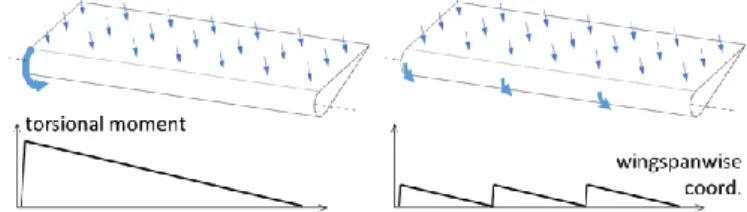
The control surface structure, as a beam along the hinge line, withstands torsional moment due to aerodynamic forces. Figure 5 shows an aileron subjected to aerodynamic forces and actuator torque. The 3-split design maximum torsional moment is 3 times as small. The theoretical gain in mass offered by splitting a control surface in k elementary surfaces would be a k-factor, if maximum torsion stress was the only sizing criterion.
Figure 5. Effect of control surface splitting on structure
torsional moments
A finite element study was carried out to assess the actual gain. For each k=1…6, the original aileron was split in k elementary ailerons of equal hinge moment; then a structure optimization was computed for each elementary aileron:
Objective: minimize overall structural mass.
With respect to design variables: thickness of each part: spars, ribs, upper and lower surfaces, spar caps, rib caps.
Subject to constraints: Von Mises stress is lower than fatigue strength chosen as (30) MPa for aluminum alloy with a security factor of 2, thicknesses remain above manufacturing minimum value chosen as 1.5 mm for the spar caps, 1 mm for the rib caps, 0.5 mm for the other parts.
Each model featured: - 2 spars
- 2 outer “secondary” ribs
- 2 inner “main” ribs, fitted with rigid elements (Nastran RBE2) in a 25 mm radius zone around the hinge line to avoid unrealistic stress concentrations. The master nodes get respectively:
o a ball joint boundary condition that accounts for a pivot-type linkage,
o a ball joint condition with zero rotation around the hinge line, that accounts for the combination of a pivot junction and the actuator action.
- uniform 2850 Pa pressure on the lower surface as the aerodynamic loading
A preliminary buckling study led us to change the minimum thickness of the front spar to 1.25 mm.
Figure 6. Von-Mises stress visualization for elementary
surface
Figure 6 shows Von Mises stresses on an elementary control surface model after optimization.
The set of computations yielded the mass of every elementary control surface for each configuration, hence the mass of the set of elementary control surfaces for each configuration, as shown in Figure 7.
Figure 7. Effect of number of surfaces on total control
surface structural mass
The gap between the theoretical mass and the FEM optimization results show that the theoretical approach is not well suited and more detailed design that incorporated buckling and other effects is mandatory. Thus, FEM results are fitted with linear regression (Equation 11) to consider the effect of the number of surfaces on total structural mass.
3 . 0
0
.
28
surf structN
M
(11)
3.2 Surface/wing attachment
Each control surface is usually linked to the wing rear spar by two cantilever attachments. Splitting the control surface increases the number of attachments. The effect on total mass is taken into account.
Conventional designs feature enough space between the spar and the aileron chordwise, to fit the linear actuators. Using rotary actuators located on the hinge line of the aileron frees that space. The only requirement considered for choosing the cantilever length is that the rotary actuator has to be assembled to its final location through that space, so the distance from the spar to the hinge line has to be at least 1.5 times the actuator outer diameter.
This study assumes that the wing structure is designed accordingly, which is beneficial as it allows more space for fuel inside the wing box.
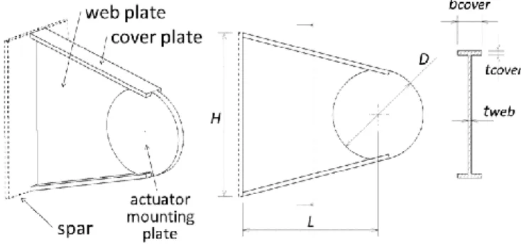
The optimization procedure requires the attachment mass to be assessed. Figure 8 shows the geometry and the adjustable dimensional parameters.
Figure 8. Attachment geometry
The list of considered sizing criteria consists in:
- resistance as the control surface is subjected to vertical aerodynamic force:
o {1} strength of the cover plates o {2} buckling of the web plate - vibratory requirements:
o {3} natural frequency of the mounted control surface has to be above 125 Hz For each of those, an analytical expression is developed: {1} The maximum stress in the cover plates is calculated near the spar and near the actuator using beam theory {2} Allowable shear stress is assessed using formula for infinitely long rectangular plate:
2
/
1
.
34
.
5
2D
L
t
E
wp allow
(12)Where
E
is the Young’s modulus of the material,
the Poisson coefficient{3} Two natural modes are considered: lateral (i.e. horizontal) and vertical translation of the control surface. The moving mass is taken as the sum of the elementary aileron structure mass and the mass of two actuators:
{3a} lateral stiffness of attachment is assessed considering independent bending stiffness of both cover plates as beams:
3
.
2
.
.
3
2
2
cp cp cp latL
I
E
k
k
(13) cpk
being the lateral stiffness due to only one cover plate,12
/
.
b
3t
I
cp
cp the quadratic moment of the cover plate.M
k
f
lat lat
2
1
(14){3b} vertical stiffness of attachment is assessed considering bending and shearing of the attachment as a beam.
IV ACTUATION SYSTEM SIZING
4.1 Aileron control surface
The studied aircraft is an Airbus A320. The aileron control surface is composed of elementary control surfaces split so that the hinge moment is the same for each of them. Each elementary surfaces are controlled by two EMAs. EMAs can be in active/active mode or active/damping mode.
Some assumptions are made for control surface splitting:
The value of the reflected inertia requirement is divide by the number of surfaces.
The available length for EMAs and attachments are the total length divided by the number of surfaces with 50% margin for mounting and uncertainties. The sizing, optimization and design space exploration is achieved using an in-house sizing framework [DEL2 2017]. The sizing problem involves 104 analysis functions including the ones outlined in previous parts of the paper. The optimization problem is the following:
Objective: minimize overall mass.
With respect to design variables: number of surfaces, motor stator external diameter, motor yoke thickness, motor current density, Harmonic Drive reduction ratio, housing thickness, wing/surface attachment flange width and 2 consistency variables for multidisciplinary couplings.
Subject to constraints: horizontal and vertical resonance frequency of the system, flexion stress of attachment, maximum diameter and maximum length of EMAs, housing stress, motor hot spot temperature, EMA skin temperature, maximum reflected inertia and 2 consistency constraints for multidisciplinary couplings.
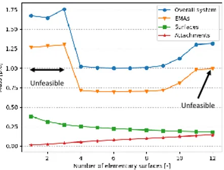
The optimization leads to a configuration where the control surface is split in 6 elementary surfaces. Figure 9 shows that the effect of control surface splitting on the overall mass is not significant after 4 surfaces.
Unfeasible
Unfeasible
Figure 9. Effect of number of surfaces on optimal mass
It is important to note that a large number of surfaces penalizes maintenance cost as the number of actuators to unmount/mount are greater.
The mass is normalized with the optimal mass value of the 6 surfaces configuration. For configurations with 1, 2, 3 and 12 individual surfaces the design is unfeasible for the chosen EMA architecture and thermal environment assumptions. For configurations 1, 2 and 3 the thermal constraints lead to large EMA which do not fit in the allocated space. For configuration 12, the maximum length is unachievable for the required torque.
It is chosen to investigate the effect of the natural convection thermal resistance on the design. This is achieved for the 6 surfaces configuration and mass are normalized for the nominal value of thermal resistance. It consist in the cylinder housing presented previously with no duct. We propose to reduce the housing thermal resistance by a factor from 1 to 4. The resulting overall mass are given in Figure 10.
Figure 10. Impact of reduction of natural convection
thermal resistance on optimal mass
Results show a significant positive effect of decreasing thermal resistance value on the total actuators mass and therefore the system mass. The effect slows down when the motor hot spot temperature constraint becomes active.
Decreasing this thermal resistance value can lead to interesting performances and characteristics of EMAs. This can be done by studying more deeply thermal boundary conditions of EMA as natural convection is a confined space is very pessimistic as in reality EMA exchange by thermal conduction with the structure. Furthermore, cooling technologies can bring significant insights for flight control EMA technologies. Nevertheless, a further studies should include a distinction between permanent torque and maximal torque during sizing of actuators should be done especially for surfaces different than aileron.
4.2 Primary flight control actuation system
The concept of control surface splitting can be extended to multiple surfaces. For simplicity reasons, the sizing models used for all surfaces are the ones used for the aileron. The only modifications are the required total moment and the maximum length of surfaces. The conceptual sizing reveals that a solution exists where one same actuator can be used
for ailerons, elevators and rudder if the surfaces are split correctly. For that the sizing problem is extended to multiple control surfaces. An illustration of the concept is given in Figure 11.
Figure 11. Aileron, elevator and rudder control surface
splitting visualization using OpenVSP [OPE]
The application of such concept can result in unneglectable benefits in terms of mass, non-recurring costs and maintenance costs. Nevertheless, a holistic design approach and well suited sizing tools are mandatory to evaluate the feasibility of such concept during actuation system and control surface layout preliminary design studies. Furthermore, thermal and structural models should be achieved specifically for elevator and rudder as done for aileron.
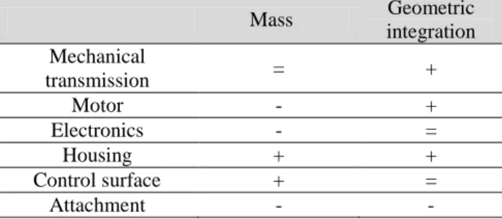
Advantages and drawbacks of control surface splitting at control surface and actuation level are summarized in Table 1.
Table 1. Positive (+), negative (-) and neutral (=) effects of
control splitting on mass and geometric integration Mass Geometric integration Mechanical transmission = + Motor - + Electronics - = Housing + + Control surface + = Attachment - -
At flight control and aircraft level control surface splitting increases reliability and control freedom. For example, on Airbus A380 aileron and rudder control surface splitting enabled better passenger comfort and structural loading. For assessment at aircraft level, an aircraft design loop and aero-structural studies are mandatory.
CONCLUSION AND FUTURE WORK
The work reported in this paper is a significant advancement in primary flight control actuation system concepts. A compact and easy integration rotary EMA has been designed and presented. Effects of aileron control surface splitting on overall mass of an equipped surface have been studied. The main benefits come from structural components like control surface and actuator housing. Impact of thermal environment and number of elementary surfaces on overall mass were given. The concept of standardized multi-surface rotary on hinge EMA has been proposed.
This study shows how important it is to have a sophisticated sizing tools for integration trade-off when designing complex multi-engineering specialization systems that primary flight control actuation systems are. The use of parametric sizing models combined with analytic derivatives and gradient based optimization enables rapid decision making during preliminary design activities as well as assessment for impacts of requirement and technology modifications on performances.
REFERENCES
Arriola, D., Schafër, A., Thielecke, F., Hauber, B., Metzler, D., Rottach, M. (2016), A Model-Based Method to Assist
the Architecture Selection and Preliminary Design of Flight Control Electromechanical Actuators, 7th International Conference on Recent Advances in Aerospace Actuation Systems and Components.
Budinger, M., Reysset, A., Halabi, T. E., Vasiliu, C., & Mare, J. C. (2014), Optimal preliminary design of
electromechanical actuator, Proceedings of the Institution of Mechanical Engineers, Part G: Journal of Aerospace Engineering, 228(9), 1598-1616.
Delbecq, S., Tajan, F., Budinger, M., Maré, J-C. & Sanchez, S. (2017), A framework for the conceptual and
preliminary design of embedded mechatronic systems, International Workshop on aircraft System
Technologies.
Delbecq, S., Budinger, M., Hazyuk, I., Sanchez, F., & Piaton, J (2017), A framework for sizing embedded
mechatronic systems during preliminary design,
IFAC-PapersOnLine, 50(1), 4354-4359.
Derrien, J. C., Tieys, P., Senegas, D., & Todeschi, M. (2011),
EMA aileron COVADIS development (No. 2011-01-2729). SAE Technical Paper.
Derrien, J. C (2012), Electromechanical actuator (EMA)
advanced technologies for flight controls, In International
Congress of the Aeronautical Sciences.
Giraud, X. (2014), Méthodes et outils pour la conception
optimale des réseaux de distribution d'électricité dans les aéronefs, (Doctoral dissertation, Toulouse, INSA).
Hospital, F., Budinger, M., Reysset, A., & Maré, J. C. (2015), Preliminary design of aerospace linear actuator
housings, Aircraft Engineering and Aerospace Technology: An International Journal, 87(3), 224-237. OpenVSP tool, http://www.openvsp.org
Sanchez, F., & Delbecq, S. (2016), Surrogate modeling
technique for the conceptual and preliminary design of embedded actuation systems and components, ICAS
proceedings.
Sanchez, F., Budinger, M., & Hazyuk, I. (2017),
Dimensional analysis and surrogate models for the thermal modeling of Multiphysics systems, Applied
![Figure 2. Motor electromagnetic and thermal FEM simulations [SAN 2017]](https://thumb-eu.123doks.com/thumbv2/123doknet/12258272.320604/3.892.66.433.491.639/figure-motor-electromagnetic-thermal-fem-simulations-san.webp)
![Figure 3. EMA housing FEM multi-physical simulations [SAN 2016]](https://thumb-eu.123doks.com/thumbv2/123doknet/12258272.320604/4.892.483.807.426.505/figure-ema-housing-fem-multi-physical-simulations-san.webp)