Publisher’s version / Version de l'éditeur:
Vous avez des questions? Nous pouvons vous aider. Pour communiquer directement avec un auteur, consultez la première page de la revue dans laquelle son article a été publié afin de trouver ses coordonnées. Si vous n’arrivez pas à les repérer, communiquez avec nous à [email protected]. Questions? Contact the NRC Publications Archive team at
[email protected]. If you wish to email the authors directly, please see the first page of the publication for their contact information.
https://publications-cnrc.canada.ca/fra/droits
L’accès à ce site Web et l’utilisation de son contenu sont assujettis aux conditions présentées dans le site LISEZ CES CONDITIONS ATTENTIVEMENT AVANT D’UTILISER CE SITE WEB.
New Horizons in Green Civil Engineering (NHICE-02), 2020-08-26
READ THESE TERMS AND CONDITIONS CAREFULLY BEFORE USING THIS WEBSITE.
https://nrc-publications.canada.ca/eng/copyright
NRC Publications Archive Record / Notice des Archives des publications du CNRC :
https://nrc-publications.canada.ca/eng/view/object/?id=5f593d1b-cc35-415c-a6dd-dd9328c48812
https://publications-cnrc.canada.ca/fra/voir/objet/?id=5f593d1b-cc35-415c-a6dd-dd9328c48812
Archives des publications du CNRC
This publication could be one of several versions: author’s original, accepted manuscript or the publisher’s version. / La version de cette publication peut être l’une des suivantes : la version prépublication de l’auteur, la version acceptée du manuscrit ou la version de l’éditeur.
Access and use of this website and the material on it are subject to the Terms and Conditions set forth at
The thermal effects of adding a window to a wood stud wall assembly
The Thermal Effects of Adding a window to a Wood Stud Wall Assembly
M. Ghobadi
a,*, J. Cingel
a, K. Kadzadej
aaNational Research Council of Canada, Construction Research Centre
* Corresponding author, (613) 990-0921, [email protected] Abstract:
Improving the thermal performance of buildings is an essential element when addressing issues related to the effects of climate change on the building envelope. Minimizing energy usage of and heat losses from buildings are important measures in achieving these associated goals. The thermal performance of a building envelope can highly impact the overall performance and energy efficiency of the building. It has been shown that the thermal resistance (R-value) of a building envelope can be affected by thermal bridging sources. Hence, it is important to accurately determine the R-value of building envelopes with thermal bridging components. In this study the thermal bridging effect of a window on wood stud wall assemblies was investigated both experimentally and numerically. A 2.4 m × 2.4 m wood-stud wall assembly, typical of North American wood-frame construction practice, was fabricated with an opening to accommodate a window. The opening in the wall assemblies was first filled with EPS and thereafter tested in the guarded hot box; following which, the EPS in the wall assembly, was replaced with a window. In this study Numerical simulation packages, THERM and WINDOW, were employed to calculate the thermal resistance of a window. The incremental effect of adding this window to a wood stud wall assembly was then investigated numerically and experimentally. COMSOL Multiphysics was employed to evaluate the effective thermal resistance of the wall and the results were benchmarked against the Guarded Hot Box (GHB) results collected in the NRC facility.
Keywords:
Window Walls, Thermal Bridge, THERM, WINDOW, COMSOL Multiphysics 1. Introduction
Adopting the Pan-Canadian Framework on clean growth and climate change in 2016, Government of Canada invested on investigations of mechanisms by which the National Model Codes (National Building Code of Canada (2015) and National Energy Code of Canada (2017)) be used to ensure building resilience and energy efficiency considering a changing climate. One specific area under investigation is in the best approaches to implement energy efficiency and clean energy technologies in Canadian building design as 17% of Canada’s total GHG emissions are associated with the built environment (12% from direct emissions and 5% from electricity generation). The heating and cooling demand of a building is the result of heat loss due to heat transmission (conduction, convection and radiation), ventilation and infiltration. In this context, it is generally recognized that the thermal performance of building envelopes can be significantly affected by thermal bridging. Thermal bridges are localized areas of high heat flow through walls, roofs and other insulated building envelope components. These paths allow heat flow to bypass the insulating layer thereby reducing the overall effectiveness of the building envelope in limiting heat transfer between the building interior and the exterior environment. Some recognized examples of thermal bridges in the building envelope include repeating structural members, balcony edges, and window frames. Additionally, as the push towards increasingly insulated building envelopes continues, the effect of thermal bridges on the effective thermal resistance of the assembly becomes increasingly significant.
In this study the thermal bridging effect of a window on wood stud wall assemblies were investigated both experimentally and numerically. A 2.4 m × 2.4 m
stud wall assembly, typical of North American wood-frame construction practice, was fabricated with an opening to accommodate a window. The opening in the wall assemblies was first filled with EPS and thereafter tested in the guarded hot box; following which, the EPS in the wall assembly, was replaced either with a window. WINDOW and THERM were employed to model thee glazing system and the results were then used in COMSOL Multiphysics to model the whole wall assembly using the three dimensional simulation configuration of the wall. The numerical results were benchmarked against results obtained experimentally from completion of standard guarded hot box tests. The results were used to study the reduction in thermal resistance for each case.
2. Methodology
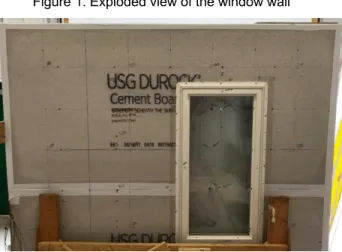
A typical 2.4 m × 2.4 m wood-stud wall assembly was fabricated with an opening to accommodate a window (Figure 1). The opening was first filled with EPS and was tested in the NRC Guarded Hot Box (GHB) facility. The EPS was then removed from the wall and replaced by a window (Figure 2).
Numerical simulations were completed on the wall assemblies in three dimensions. The modeling sequence for both series consisted of: (i) creating the geometry to be modelled; (ii) selecting the material properties; (iii) determining and applying the boundary conditions; (iv) performing a mesh verification; (v) conducting the numerical simulations, and; (vi) comparing the results to those obtained from laboratory tests.
The heat transfer in the walls was also simulated in COMSOL Multiphysics. Three dimensional simulations were chosen to capture the lateral heat transfer in the wall assemblies that occur due to the thermal bridging elements. The 3-D geometries for the wall assemblies
were created in Solidworks®. The geometries were imported in COMSOL Multiphysics and material properties were assigned to the corresponding domains. The temperature dependent thermal conductivity was used for fiberglass batt insulation and extruded polystyrene (XPS) as follow:
KFibergalss = 0.0355+0.0002Tmean Eq. 1
KEPS = 0.0388+0.0001Tmean Eq. 2
Figure 1. Exploded view of the window wall
Figure 2. Window wall which was tested in the GHB Natural convection on the interior surface and forced convection on the exterior surface were used as the hot and cold boundary conditions. Convective heat transfer coefficients were derived from the GHB results and are shown in Table 1.The symmetry boundary condition was applied on the edges of the wall.
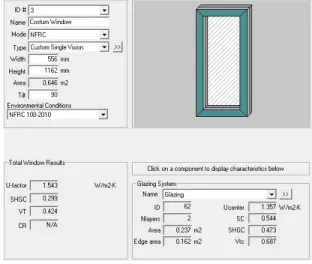
Figure 3 illustrates the window glazing system. In the WINDOW (v7.6) software, “6mm Clear Float Glass” from Guardian (WINDOW ID #3016) was used as the clear glass, and for the low-e glass, “ClimaGuard 70/36 LE on 6mm” glass from Guardian (WINDOW ID #3256) was used. The low-e coating was placed on the inner side of the glass (surface #2) to maximize thermal performance. The cavity between the glass lites (12.7 mm / 0.5-in.)) was filled with Argon gas. The glazing also had a spacer between the glass lites (which is later made in THERM). A generic spacer was chosen from
a study completed on spacer and edge seals by the Berkley Lab; his same study was also used in the NFRC manual. The spacer consisted of butyl rubber separating a 0.015-in. thick steel stud from the glazing, as well as a layer of desiccant (Silica gel) inside the stud to improve performance. This 6 mm clear, Argon, filled, low-e glazing system is generic and considered to replicate the actual glazing reasonably well. After the glazing was created in the WINDOW (v7.6) software, the frame parts (head, sill, jambs) were then created separately in THERM. The drawing was imported to THERM, where predefined THERM materials were assigned to each part of the detail. The PVC frame was assigned the THERM material “Polyvinylchloride PVC / Vinyl – Rigid” whereas the frame cavities were modeled using THERM material “Frame Cavity NFRC 100”, which is the NFRC standard for frame cavities. The spacer materials were the same as those described above. After the material selection was complete, the glazing was imported from WINDOW (v7.6).
Figure 3. The Glazing system (left) the spacer (right)
Table 1. Exterior and interior boundary conditions Tcold air(°C) Thot air (°C) Tcold surface (°C) Thot surface (°C) hcold ( ) hhot ( ) -5 21 -4.6818 19.824 32.7 9.2 -20 21 -19.513 19.19 34.0 8.9 -35 21 -34.355 18.589 34.0 8.9 The boundary conditions used for the calculations were:
• “NFRC 100 – 2010 Exterior” for the exterior edges of the frame and glazing
• “Interior Wood/Vinyl Frame (convection only)” for the interior edges of the frame
• “U-factor Inside Film” for the interior glazing • “Adiabatic” for surfaces that are connected to the wall
Laboratory thermal tests were conducted on four wall assemblies in NRC’s GHB test facility following the test procedures given in ASTM C1363. The NRC GHB test facility is a test apparatus specifically designed to determine the thermal resistance of building envelope assemblies and components by subjecting a test specimen to a temperature difference and measuring the amount of energy required to maintain interior set point conditions. The tests were conducted at two different exterior temperatures; i.e.: -20 °C and -35 °C.
3. Results and discussions
The final THERM results are shown in Figure 4Error! Reference source not found.. As is evident, a thermal transmittance of 1.543 W/m2K was obtained which is
equivalent to a R value of 3.68 ft2.hr°F/Btu or 0.648 m2K/W. The results were used to calculate the
equivalent conductivity of the window in COMSOL. AS such, and instead of modeling the window, an artificial artifact was created as a proxy material that replicates the window in terms of its thermal performance. For this wall assembly, which has a thickness of 0.243 m, the equivalent thermal conductivity of 0.375 W/m.K was used for the proxy material. The window or EPS occupy 13.3 percent of the total surface area of the wall. Also, as stated before, the wall assembly had no exterior insulation.
Figure 4. THEMR final results Table 2 and Interior surface
4. Conclusions and outlook
The incremental effect of adding a window to a wood stud frame wall assembly was studied numerically employing COMSOL Multiphysics, THERM, WINDOW and experimentally using standard guarded hot box testing. First WINDOW and THERM were used to simulate the glazing part and the frame. The results were used to assign the thermal conductivity to an equivalent and proxy material in COMSOL Multiphysics.
It has been shown that the window wall thermal performance is significantly affected by the thermal transmittance of the window. The window only occupied 13 percent of the wall, but reduced the effective thermal resistance of the wall by more than 50 percent. It also decreased the minimum temperature index on the interior surface; this can lead to less comfortable thermal conditions for the occupants in proximity to the window and as well, increases the risk to condensation on the glazing.
This is an ongoing project and additional work on this topic will be reported in the future. Now that the numerical method has been benchmarked against experimental results, additional numerical work can now be conducted to extract more results. Since, numerical simulations are time consuming and given
that access to appropriate numerical tools cannot be assumed, these results could be used to find simple correlations that thereafter, practitioners can employ to find the effective thermal resistance of window-walls. Table 3 summarize the window-wall results for the cases where the openings were filled with EPS and a window at two exterior temperatures of -5 °C and -20 °C. For the case where the exterior temperature was set to -35 °C, the calorimeter heater could not generate sufficient heat to compensate for the heat flow passing through the window-wall. Hence, the warm side temperature could not reach the desired temperature.
It can be seen that the
R-values dropped 54 percent when the window was added to the wood-stud wall assembly. The differences between the COMSOL simulation and GHB test were also found to be less than three percent and well below the uncertainty of the NRC GHB.
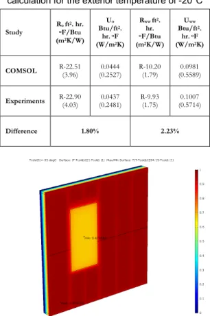
Figure 5 and Figure 6 illustrate the temperature index on the interior and exterior surfaces of the wood-stud wall assembly with the opening filled with EPS. Figure 7 and Figure 8 show the same for the wall with window in the opening. It can be seen that for the case where the EPS was used to fill the opening, wood-studs are the main source of thermal bridging and the minimum temperature index occurs near the edge of the opening where double wood-studs were used in the assembly. The temperature index on the exterior is also very uniform. Whereas, for the case having a window installed in the wall, a maximum temperature index of 0.1228 on the exterior surface was obtained whereas, and a minimum temperature index of 0.67 was achieved on the interior surface. Hence, the window is the primary element of heat flow through the wall and that evidently significantly affects the thermal transmittance of the entire wall assembly.
Figure 5. The window wood stud wall assembly with the hole filled with EPS- Values of temperature index
Figure 6. The window wood stud wall assembly with the hole filled with EPS- Values of temperature index
on the exterior surface
Table 2. Window wall and clear field results calculation for the exterior temperature of -5°C
Study Ro ft 2. hr. oF/Btu (m2K/W) Uo Btu/ft2. hr.oF (W/m2K) Rww ft2. hr. oF/Btu (m2K/W) Uww Btu/ft2. hr.oF (W/m2K) COMSOL R-22.40 (3.94) (0.2539)0.0446 R-10.17 (1.79) (0.5602) 0.0983 Experiments R-22.16 (3.90) (0.2564)0.0451 R-10.08 (1.77) (0.5650)0.0992 Difference 0.98% 0.86% Interior surface 5. Conclusions and outlook
The incremental effect of adding a window to a wood stud frame wall assembly was studied numerically employing COMSOL Multiphysics, THERM, WINDOW and experimentally using standard guarded hot box testing. First WINDOW and THERM were used to simulate the glazing part and the frame. The results were used to assign the thermal conductivity to an equivalent and proxy material in COMSOL Multiphysics.
It has been shown that the window wall thermal performance is significantly affected by the thermal transmittance of the window. The window only occupied 13 percent of the wall, but reduced the effective thermal resistance of the wall by more than 50 percent. It also decreased the minimum temperature index on the interior surface; this can lead to less comfortable thermal conditions for the occupants in proximity to the window and as well, increases the risk to condensation on the glazing.
This is an ongoing project and additional work on this topic will be reported in the future. Now that the numerical method has been benchmarked against experimental results, additional numerical work can now be conducted to extract more results. Since, numerical simulations are time consuming and given
that access to appropriate numerical tools cannot be assumed, these results could be used to find simple correlations that thereafter, practitioners can employ to find the effective thermal resistance of window-walls.
Table 3. Window wall and clear field results calculation for the exterior temperature of -20°C
Study Ro ft 2. hr. oF/Btu (m2K/W) Uo Btu/ft2. hr.oF (W/m2K) Rww ft2. hr. oF/Btu (m2K/W) Uww Btu/ft2. hr.oF (W/m2K) COMSOL R-22.51 (3.96) (0.2527)0.0444 R-10.20 (1.79) (0.5589) 0.0981 Experiments R-22.90 (4.03) (0.2481)0.0437 R-9.93 (1.75) (0.5714)0.1007 Difference 1.80% 2.23%
Figure 7. The window wood stud wall assembly with the window- Values of temperature index on the
Figure 8. The window wood stud wall assembly with the window- Values of temperature index on the
exterior surface Acknowledgements
The authors acknowledge the financial support of NRCan to support this project.
References
ASTM C1363 – 11 Standard Test Method for Thermal Performance of Building Materials and Envelope Assemblies by Means of a Hot Box Apparatus
American Society of Heating, Refrigerating and Air-Conditioning Engineers. ASHRAE Standard : Energy Standard for Buildings Except Low-Rise Residential Buildings, 2016 ASHRAE ISSN 1041-2336
Natural Resource Canada, Energy Use Data
Handbook, 2009,
http://oee.nrcan.gc.ca/corporate/statistics/neud/dpa/h andbook (retrieved 2013).
EN ISO 10211: Thermal Bridges in Building Construction – Heat Flows and Surface Temperatures – Detailed Calculations, 2007.
EN ISO 14683: Thermal Bridges in Building Construction – Linear Thermal Transmittance Simplified Methods and Default Values, 2007.
Lawrence Berkley National Laboratory, "THERM 6.3/WINDOW 6.3 NFRC Simulation Manual," Berkley Lab, 2011.
Pan-Canadian Framework on Clean Growth & Climate Change – Environment & Climate Change Canada, 2016.
S. Van Der Bergh, R. Hart, B. Petter Jelle and A. Gustavsen, "Window Spacers and Edge Seals in Insulating Glass Units: A State-of-the-Art Review and Future Perspectives," Energy and Buildings, 2013.