• Aucun résultat trouvé

Fast Grasp Planning Using Cord Geometry

N/A
N/A
Protected

Academic year: 2021

Partager "Fast Grasp Planning Using Cord Geometry"

Copied!
26
0
0

Texte intégral

(1)

HAL Id: hal-01250418

https://hal.inria.fr/hal-01250418

Submitted on 5 Jan 2016

HAL is a multi-disciplinary open access

archive for the deposit and dissemination of

sci-entific research documents, whether they are

pub-lished or not. The documents may come from

L’archive ouverte pluridisciplinaire HAL, est

destinée au dépôt et à la diffusion de documents

scientifiques de niveau recherche, publiés ou non,

émanant des établissements d’enseignement et de

Fast Grasp Planning Using Cord Geometry

Yi Li, Jean-Philippe Saut, Julien Pettré, Anis Sahbani, Franck Multon

To cite this version:

Yi Li, Jean-Philippe Saut, Julien Pettré, Anis Sahbani, Franck Multon.

Fast Grasp

Plan-ning Using Cord Geometry.

IEEE Transactions on Robotics, IEEE, 2015, 31 (6), pp.11.

(2)

Fast Grasp Planning Using Cord Geometry

Yi Li, Jean-Philippe Saut, Julien Pettr´e, Anis Sahbani, and Franck Multon

∗†‡§

January 5, 2016

Abstract

In this paper, we propose a novel idea to address the problem of fast compu-tation of stable force-closure grasp configurations for a multi-fingered hand and a 3D rigid object represented as polygonal soup model. The proposed method per-forms a low-level shape exploration by wrapping multiple cords around the object in order to quickly isolate promising grasping regions. Around these regions, we compute grasp configurations by applying a variant of the close-until-contact pro-cedure to find the contact points. The finger kinematics and the contact information are then used to filter out unstable grasps. Through many simulated examples with three different anthropomorphic hands, we demonstrate that, compared with pre-vious grasp planners such as the generic grasp planner in Simox, the proposed grasp planner can synthesize grasps that are more natural-looking for humans (as measured by the grasp quality measure skewness) for objects with complex ge-ometries in a short amount of time. Unlike many other planners, this is achieved without costly model preprocessing such as segmentation by parts and medial axis extraction.

Grasping, Multifingered Hands, Dexterous Manipulation, Service Robots, Domes-tic Robots.

1

Introduction

Grasp planning research has long been focused on theoretical analysis of grasping us-ing idealized models of both the robotic hand and object. With the arrival of more affordable robotic manipulation platforms and sensors, the study of robotic grasping has advanced towards the development of algorithms that work with real data (e.g., point clouds from RGBD sensors and images from stereo cameras) [1–5]. However, these algorithms are often limited to simple grippers and/or simple objects (e.g., books, water bottles, and wine glasses).

This work was supported in part by Institut Carnot Inria.

Y. Li and J. Pettr´e are with MimeTIC, IRISA/Inria Rennes—Bretagne Atlantique, 35042 Rennes, France

(e-mail: yi.li@outlook.com; julien.pettre@inria.fr).

J.-P. Saut and A. Sahbani are with Institut des Syst`emes Intelligents et de Robotique, CNRS UMR 7222,

Universit´e Pierre et Marie Curie, 75252 Paris, France (e-mail: saut@isir.upmc.fr; sahbani@isir.upmc.fr).

§F. Multon is with team MimeTIC and Laboratoire M2S, Universit´e Rennes 2, ENS de Rennes, 35170

(3)

With the introduction of next generation of 3D laser scanners and Microsoft’s Kinect, and algorithms such as Kinect-Fusion [6] that merges several low resolution point clouds of one scene into a high definition cloud, we believe it is time to proceed to the next step that is grasp planning of complex objects represented by imperfect but detailed mesh models built using 3D laser scanners or Kinect. These meshes can even be non-manifold and have holes. Furthermore, we intend to give researchers, who are not familiar with robotic grasping (e.g., researchers who are in the field of digital character animation), an easy-to-implement grasp planner.

In this paper, we present an innovative and intuitive grasp planner to synthesize grasps for objects with complex shapes such as objects consisted of multiple parts (e.g., a pair of pliers). The strategy is to tightly wrap multiple sets of cords [7] around an object in order to quickly obtain information about its shape and extract the promising grasping regions. By placing a non-stiff cord that is made up of a sequence of linear segments around the object and then tightening it, the object’s local geometry under the cord is revealed. To find out more about the local geometry, several parallel or almost parallel cords are added. The procedure of cord generation is conceptually similar to the computation of a two-dimensional convex hull [8]. The main reason for choosing cords is their ability to provide a not only intuitive, but also interactive technique for specifying curves with physics-like properties [7]. For example, to lift an object with major surface bumps, ridges, and grooves such as a Stegosaurus toy with its dermal plates, non-stiff cords used in this paper can be replaced with stiff cords. A stiff cord’s resistance to bending sharply around object increases with increasing stiffness. When stiffness is equal to zero, a stiff cord is equivalent to the corresponding non-stiff cord.

This paper is an extension of [9]. Apart from more extensive evaluation of the cord-driven grasp planner and the addition of comparison with grasps synthesized by the generic grasp planner in Simox [10] (a C++ toolbox containing, among other libraries, a grasp planning library), the main difference between this version and the previous one [9] is the introduction of grasp measure XOR χ: This new measure is based on polygon clipping instead of the lengths of the cords. Furthermore, our implementation is now built on top of Simox and relies on it for many standard grasp planning functions such as grasp stability evaluation.

The paper is organized as follows. After a comparison to previous work in Sec-tion 2, the proposed grasp planner is presented in two secSec-tions. SecSec-tion 3 explains how cords are constructed around sections of an object and how candidate hand poses are obtained, whereas Section 4 details how finger configurations are computed and how the resulting grasps’ stability is checked. Simulation results obtained with various household objects from the KIT ObjectModels Web Database [11], among others, are shown in Section 5.

2

A Comparison to Previous Work

Compared with previous planners that synthesize grasps for complex objects [12–19], our cord-driven grasp planner has several advantages.

First, the proposed grasp planner enables the grasping of objects with more com-plex geometries. For example, our grasp planner can synthesize grasps that grab both

(4)

handles of a pair of pliers by wrapping multiple sets of cords around it. A grasp re-gion is then defined as the rere-gion spanned by a set of cords. After evaluating all grasp regions, our grasp planner tends to choose the grasp that is synthesized around a set of cords that wraps around both handles. Grasp planners that look for shapes that are likely to fit into the robotic hand and maximize the surface area of contact [14, 16, 17] can not make such a grasp.

Second, the proposed grasp planner eliminates the need for costly preprocessing such as shape segmentation/approximation [13, 15] and medial axis computation [18]. For example, our grasp planner can not only synthesize grasps for a bottle without having to approximate it with a cylinder, but also synthesize grasps for a sickle-shaped object without computing its medial axis.

Third, grasps synthesized by the proposed grasp planner are more similar to human-planned grasps compared with grasps synthesized by previous approaches such as the generic grasp planner in Simox [10], because the most promising grasp regions will be covered by similar cords [16] and the grasp measure XOR χ enables us to find these re-gions. To evaluate how natural-looking a grasp is for humans, we use the grasp quality measure skewness [20]. For example, given a long cylinder to be grasped, most people align the wrist almost perpendicularly to the largest principal axis of the cylinder and grasp the smallest principal axis, which corresponds to low skewness. Furthermore, it is also shown in [20] that grasps with low skewness were significantly more robust, and they were preferred by the human subjects independent of the task. Even though it is certainly possible to add grasp quality measure skewness into existing grasp planners, how to integrate it with other grasp quality measures such as epsilon [21] and our grasp measure XOR χ is beyond the scope of this paper. In [22], a novel grasp synthesis method for solving the configuration problem (i.e., configure the hand relative to the object so that each hand region establishes contact on its corresponding object region) was presented. It was then extended in [23] with a procedure for optimizing the qual-ity of the obtained grasps. Even though the resulting grasp configurations in [22, 23] appear quite natural-looking for humans, the final result produced by these methods is in some sense guided by a given set of contact constraints, because they require that both regions on the surface of the hand, and corresponding regions on the surface of the object are given as inputs.

Fourth, unlike [14, 17, 19], the proposed grasp planner works with objects rep-resented by non-manifold polygonal meshes. The test cases demonstrate that objects with small surface bumps, ridges, and grooves can be easily handled. In fact, even poly-gon meshes with holes can be used to represent objects. Furthermore, unlike [22, 23], our grasp planner makes no assumption that the surface normal vectors always point outward from the surface.

Fifth, the proposed grasp planner can be implemented easily, because the compu-tation consists mostly of geometrical calculations. Our grasp planner is now built on top of Simox, thus we have greatly reduced the number of lines of code. Furthermore, our grasp planner does not require grasp prototypes (i.e., example grasps), unlike [12]. Finally, compared to the methods in [22, 23], our grasp planner is not only much easier to be implemented, but also less computationally involved.

(5)

3

The Exploration Stage

In this section, we detail how multiple sets of non-stiff cords are wrapped around an object to delineate its geometry. First, we describe how we construct one cord by tightening a seed guide curve in the shape of a triangle around the object (Section 3.1). If the grasping region under the cord is promising, we construct the rest of the set by rotating the seed guide curve around one of its vertices to generate additional guide curves (Section 3.2) and tightening them. Next, we explain how we synthesize the seed guide curve by random sampling the corresponding triangle’s three vertices in Section 3.3. Lastly, we present grasp measure XOR χ to compare and sort the promising grasping regions (Section 3.4).

3.1

Cord Generation

To generate a cord, we follow the algorithm presented in [7]. The cord’s resistance to bending is modeled by its stiffness property. In this paper, we are only interested in non-stiff cords because we seek to use cords to reveal the overall surface geometry of objects and non-stiff cords wrap more tightly around objects, whereas stiff cords are resistant to bending [7]. Before a non-stiff cord can be constructed, a guide curve that does not intersect with the object must be created. In Fig. 1, the black curve on top of the cyan rectangular object with 3 indentations is the guide curve. After choosing one of the two extreme points of the guide curve as the initial point, and adding it to the empty cord, rays are repeatedly cast towards the guide curve, away from the most recently added point in the cord. Whenever a ray intersects with the object, a grazing intersection is added to the cord. The process is repeated until the final point of the guide curve is reached. The green curve in Fig. 1 is the generated non-stiff cord that is made up of a sequence of linear segments. For full details relating to the cord generation algorithm, we refer the reader to [7].

Guide Curve

Non−stiff Cord

Figure 1: Geometric construction of a non-stiff cord.

In order to grasp an object stably, it is preferable that a cord encloses the object or part of it completely. However, if the object or part of it to be grasped is too big or wide for the hand, a cord that does not entirely enclose the object or part of it can be constructed instead. Consequently, we distinguish a cord enclosing the object or part of it completely, and enclosing the object or part of it only partially.

(6)

Case I As shown in Fig. 1, the cord constructed by the standard cord generation algorithm does not enclose the rectangular object. In fact, in two line segments out of three they do not follow the overall object geometry. Here, we present a two-step procedure that encloses the target object or part of it using two cords. For the first

step, an acute triangle 4P1P2P3 (formed by line segments P1P2, P2P3, and P3P1)

is chosen as the guide curve as shown in Fig. 2, where segments P1P2 and P1P3can

be compared to the thumb and index finger, respectively. After executing the standard cord generation algorithm, we obtain a cord (the red one in the left subfigure in Fig. 2) that wraps around the object geometry except for its first and last segments. We obtain the red cord shown in the right subfigure by removing these two segments from the

cord. In the second step, the guide curve is defined by the following segments: PrP3,

P3P1, P1P2, and P2Pl. The second cord (the green one in the right subfigure) is then

constructed by applying the standard cord generation algorithm. As shown in the right subfigure, after removing the first and last segments, the red and green cords wrap around the object geometry completely. Since these two cords are connected at points

Pl and Prand they separate the visible part from the hidden part as seen from point

P1, we denote the green and red cords as the front and back cords, respectively, where

the front cord is defined by a sequence of points {Pr, Pρ, . . . , Pλ, Pl}. Consequently,

Pr and Pρ bind the first segment of the front cord, whereas Pλ and Pl bind the last

segment. If the front cord is made up of three line segments, then Pρand Pλrepresent

the same point (i.e., the middle one). If there is only one line segment in the front cord,

Pρand Pλare not defined, and the only segment is bounded by Prand Pl.

Guide Curve Back Cord Front Cord P1 Pl Pr P2 P1 Pl Pr P3 P2 P3 Pλ Pρ

Figure 2: Geometric construction of two non-stiff cords that completely encloses an object.

The border points Pland Prare not the actual contact points between the hand and

object. The contact points are determined later in Section 4. However, if Pl and Pr

meet the eligibility criterion described below, these two points are denoted as virtual grasping points. Let variable ξ characterize the size of the front cord, where ξ is the

maximum distance between the midpoint of line segment PlPrand the front cord. The

eligibility criterion is then defined as: ξmin≤ ξ ≤ ξmax. Essentially, variable ξ is used

to quickly assess that the part of the object under the front cord is neither too small nor too large for the hand. Because the stability of each grasp will be checked later in the finger configuration computation stage (Section 4), there is no need to determined

the exact values of ξmin and ξmax. In this paper, three different dexterous hands,

(7)

(right) hand are used to test our cord-driven grasp planner. The values of ξmin= 1.5cm

and ξmax = 7.5cm are used for all three dexterous hands. If Pl and Pr meet the

eligibility criterion, P1gives the initial hand position, whereas the triangle 4P1PrPl

defines the hand orientation, as will be described in detail later.

Case II In the previous case, we have assumed that the virtual grasping points

Pl and Pr are always visible from P1. Unfortunately, this assumption is restrictive,

because virtual grasping points that are not visible from P1 are necessary when, for

example, grasping a wide object such as a book as shown in Fig. 3. To handle this

case, we start from an acute triangle 4P1P2P3as before, but line segment P2P3must

intersect with the object this time. The two intersection points that are closest to P2

and P3 are denoted as Pl and Pr (see Fig. 3), respectively. The front cord is then

constructed by using line segments PrP3, P3P1, P1P2, and P2Pl as the guide curve;

therefore, the local geometry of the object under the front cord is delineated despite

the fact that Pland/or Prmay be invisible from P1. Pland Prare classified as virtual

grasping points if and only if the above criterion mentioned before is met in addition

to the following criterion: The angle between vectors−P−−λ→Pl and

−−−→

PρPr should be as

small as possible if rays−P−−lP→λand

−−−→

PrPρintersect, because the object is more likely to

slip if the angle is too big, imagining that the fingertips of the thumb and index finger

are placed at Pland Pr, respectively. In all the experiments, the maximum threshold

of the angle was set to a reasonably conservative value: 14π. The exact value of this

threshold depends on many factors such as coefficients of friction of the object and hand, whether soft contacts are enabled, and the object’s center of mass. Fortunately, there is no need to determine the exact value of the threshold, as the stability of each grasp will be checked later in Section 4.

Guide Curve Front Cord P1 P1 P2 P3 P2 P3 Pr Pl Pλ Pρ

Figure 3: Geometric construction of a non-stiff cord that wraps around part of a wide object.

3.2

Object Scanning Using Cords

In Section 3.1, we presented a method for generating two virtual grasping points on the surface of an object with a front cord that wraps around the object. However, the

(8)

information contained in this single cord is not sufficient to verify whether the region around the cord is a promising grasping region. Similar to the way a single laser beam is used to scan an object, we can shift the guide curve up and down in order to construct additional front cords, and hence obtain more information about the region.

To construct a set of front cords, we start with a seed cord: a promising front cord along with two corresponding virtual grasping points found in Section 3.1. The guide

curve from which the seed cord is derived is called the seed guide curve (i.e., t0 in

Fig. 4). As shown in Fig. 4, t0is then shifted up and down to generate additional guide

curves called upper / lower guide curves, respectively. The shift is accomplished by

rotating the seed guide curve around the axis defined by P1and the cross product of two

vectors. This first vector is the normal of the plane of the seed guide curve. The second

vector is the one that points from P1to the midpoint of line segment PlPr(defined in

Section 3.1). As will be described further in this paper, the second vector defines the

approach direction for the hand, whereas P1gives the initial hand position. For each

shift upward, the seed guide curve is rotated by angle iupθ, where θ > 0 and iup is

the current number of upward shifts. For each shift downward, the seed guide curve

is rotated by −idownθ instead, where idownis the current number of downward shifts.

If segment P2P3on the seed guide curve intersects with the object, the corresponding

segment of any additional guide curve must also intersect with the object. Similarly,

if P2P3on the seed guide curve does not intersect with the object, the corresponding

segment of any additional guide curve is considered to be invalid if it intersects with the object. Essentially, we separate the two cases mentioned in the previous subsection due to the fact that the most promising grasp regions will be covered by similar front cords [16]. When the object is scanned with guide curves and a guide curve of one case is followed by a guide curve of another case, the two resulting front cords are unlikely to be similar to each other. This process is repeated until enough front cords

are generated so that the distance traveled by the line segment P2P3 is roughly equal

to the width of the palm. Note that the number of additional guide curves we generate around the seed guide curve depends not only on the chosen hand, but also on angle θ. Lastly, we stipulate that the numbers of additional guide curves in both directions must be equal, because the front cord derived from the seed guide curve defines the initial orientation of the hand; hence, the seed guide curve should always lie in the middle.

3.3

Random Sampling of Guide Curves

Thus far, we have simply stated that the guide curve is given. In this subsection, we present a method that randomly samples guide curves for household objects such as items from the KIT ObjectModels Web Database. Different random sampling schemes are required to grasp other kinds of objects (e.g., larger ones such as tables), although they are beyond the scope of this paper.

First, we construct a bounding sphere s for the object. As shown in Fig. 5, the bounding sphere is centered at the object’s barycenter C and its radius is r. Second,

two additional spheres that are also centered at C are constructed: sphere s1with radius

r1and sphere s2with radius r2, where r2is slightly greater than r and r1= r2+ ∆r,

where ∆r = 10cm and 10cm is the average length of a male’s fingers. The value of r2

(9)

rotation axis Guide Curves P1 t+2 t+1 t0 t−1 t−2 P3 P2

Figure 4: The seed guide curve t0is shifted up and down in order to generate additional

guide curves.

the surface of the sphere), the cord does not intersect with sphere s, whereas the value

of r1was chosen such that it is unlikely that the object and hand would collide when the

hand is placed on s1and its opening is facing the object. If the hand collides with the

object, our cord-driven grasp planner simply moves the hand away from the object until there is no collision before closing the fingers around the object. Consequently, we are able to utilize ∆r = 10cm for all three robotic hands in the experiments. Third, a deterministic sampling method [24] is employed to sample three uniform deterministic

sequences of samples Φ1, Φ2, and Φ3on the surfaces of spheres s1, s2, and s2(again),

respectively. Fourth, in order to generate a guide curve, three points are randomly

selected among the points in the deterministic sequences Φ1, Φ2, and Φ3 as P1, P2,

and P3, respectively. Among the three points, P1 defines the initial position of the

hand. Finally, if 4P1P2P3is acute, it is used as the guide curve to scan the object (as

described in Sections 3.1 and 3.2). The whole process is summarized in Algorithm 1, where the outer loop iterates at most M times, whereas the inner loop iterates at most

N times, which is also the size of sequences Φ1, Φ2, and Φ3. We set M and N to 1000

and 10000, respectively. Instead of this brute force method to sample acute triangles in 3D, a more involved solution can be derived from the procedure in [25]. Furthermore, in our current implementation, the sequences of sampled acute triangles are not stored and hence we re-sample for every object even if two objects’ bounding spheres have the same radius. Since the spheres are quasi-independent from the object, the sequences of sampled acute triangles could be stored.

After a set of front cords have been generated in Algorithm 1, a local improve-ment procedure is applied to improve the performance of our grasp planner such that

additional sets of front cords are generated by sampling further poses for 4P1P2P3

around its current pose. This inspiration comes from the field of motion planning: Non-uniform measures are employed by most probabilistic roadmap (PRM) planners in order to dramatically improve performance, whereas the basic PRM uses the uniform sampling measure [26].

(10)

r1 P1 C r2 S1 r P3 P2 S2

Figure 5: Sampling of a guide curve on the surfaces of two spheres. Algorithm 1: Random sampling of guide curves.

input : An object and its bounding sphere defined by a barycenter C and a radius r;

1 s1← a sphere of radius r1, centred at C; 2 s2← a sphere of radius r2, centred at C;

3 Φ1← a uniform deterministic sequence of samples over sphere s1; 4 Φ2← a uniform deterministic sequence of samples over sphere s2; 5 Φ3← a uniform deterministic sequence of samples over sphere s2; 6 for i = 1 to M do

7 Rearrange elements in Φ1, Φ2, and Φ3randomly; 8 for j = 1 to N do

9 P1← Φ1[j], P2← Φ2[j], P3← Φ3[j]; 10 if 4P1P2P3is acutethen

11 Scan object surface with 4P1P2P3as the guide curve;

3.4

Evaluating Grasp Regions

In order to check whether the region covered by a set of front cords generated in Sec-tion 3.2 is a promising grasping region or not, we propose a polygon-clipping-based grasp measure XOR χ to determine how similar the front cords are to each other, be-cause a promising grasp region will be covered by similar front cords according to [16]. In this subsection, we explain the grasp measure XOR through one example.

Suppose that we want to synthesize a grasp for the cylinder shown in Fig. 6.

Af-ter constructing a set of guide curves around the seed guide curve 4P1P2P3and then

generating the corresponding front cords by tightening the guide curves, we need to

evaluate whether P1is a correct initial position for the hand and the region covered

by the front cords is a promising grasping region. From each front cord (shown as blue curves in Fig. 6), we construct a convex polygon by connecting its two end-points. All convex polygons are then projected orthogonally onto the plane spanned by

4P1P2P3. We denote the resulting 2D convex polygon as Qi, where i ∈ {−n, −(n −

1), . . . , 1, 0, 1, . . . , n − 1, n} and n is the number of upper / lower front cords. Note

that Q0is the one derived from the seed front cord. Next, we compare each projected

(11)

we perform the Boolean XOR operation (exclusive-or) on both convex polygons. The smaller the area of the resulting polygon, the more similar are the two input polygons. Fig. 7 shows the result of the Boolean XOR operation applied to two convex polygons. Consequently, our polygon-clipping-based grasp measure XOR χ is defined as

χ = 1 2n n X i=−n A(Qi⊕ Q0), (1)

where A is the area symbol and ⊕ represents the XOR operator. Note that the sum is averaged over the total number of upper and lower front cords (i.e., 2n).

In the left subfigure in Fig. 6, the red polygon represents the intersection between

the cylinder and the plane defined by the given 4P1P2P3 (points P2 and P3 not

shown), whereas the green represents the intersection between the cylinder and the plane spanned by an upper / a lower guide curve. The right subfigure in Fig. 6 shows

the intersections for a different 4P1P2P3. The projected 2D convex polygons

corre-sponding to the right subfigure in Fig. 6 are shown in Fig. 7 along with the polygon outputted by the polygon clipper after performing the Boolean XOR operation. In the two examples shown in Fig. 6, the left one is preferable because the angle between the approaching direction of the hand and the cylinder’s largest principal axis is closer to

90◦; hence, its grasp measure XOR score is lower.

We use the Vatti clipping algorithm [27] for clipping because it is extremely fast as a result of: (1) The 2D polygons used in our calculations have only a small number of edges; (2) Our polygons are convex, and hence there are no self intersecting polygons to be taken account of.

Figure 6: Intersections (ellipses) between a cylinder and two sets of guide curves. For clarity, only two ellipses are shown for each set. Front cords are drawn in blue.

4

Computing finger configuration from a grasp region

Around the promising grasping regions identified in Section 3, we look for a stable force-closure grasp in this section. In other words, after finding out the wrist pose,

(12)

Figure 7: The two 2D polygons shown in the first two subfigures originate from the intersections shown in the right subfigure of Fig. 6. After performing the Boolean XOR operation on these polygons, the polygon clipper outputs one 2D polygon (the striped region shown in the third subfigure).

which is given by a previously identified grasp region, we now need to calculate how the fingers should be placed/closed on the object. A common procedure is to set the hand in a preshape configuration and then close the fingers until they contact the object surface. The closing motion is predefined from the knowledge of the hand specific kinematics. This method has been widely used in the literature (e.g., in [4, 10, 18, 28]) and in grasping simulators such as GraspIt! and Simox. Its main advantages are its simplicity and that it allows contact anywhere on the finger surface. The procedure described in this section is based on the one implemented in Simox and hence suitable for robot hands built with rigid parts. If an adaptive and soft hand such as the Pisa/IIT SoftHand [29] is used instead, the procedure needs to be modified accordingly. For example, soft finger contact must be considered instead of hard finger contact.

4.1

Synthesizing Grasps from the Seed Front Cord

If the region under a set of front cords is considered to be a promising grasping region,

points {P1, Pl, Pr} define the initial position and orientation of the hand relative to the

object, where Pland Prare located on the seed front cord (i.e., the middle one of the

set), whereas P1is on the seed guide curve (i.e., the guide curve that gave rise to the

seed front cord). More specifically, the hand’s approach direction is given by−−−→P1Pm,

where Pmis the midpoint of line segment PlPrand the rotation of the hand around

the approach direction is determined by the normal to the plane spanned by points

{P1, Pl, Pr}, instead of being randomly sampled as done by the generic grasp planner

in Simox. To close the hand around the object, the hand is moved towards the object until the hand’s Grasp Center Point (GCP) [10] reaches the object surface or the hand intersects with the object. In the latter case, the hand is moved away until it no longer intersects with the object. Finally, the fingers are closed around the object.

4.2

Assessing the Grasp Stability

In order to check grasp stability, we rely on the grasp wrench space computation im-plemented by Simox. First, Simox constructs 6D wrenches from the contact informa-tion [28, 30, 31] to represent the contact force and torque. Second, a quality measure is obtained from the analysis of the convex hull of all contact wrenches. The resulting grasp is considered to be force-closure by Simox, if the convex hull contains the origin of the wrench space as an interior point. Third, the minimum distance between the

(13)

origin of the wrench space and the convex hull surface demonstrates the ability of the grasp to compensate for external disturbances; hence, it is used by Simox as the grasp quality metric.

5

Test Cases

In this section, we show that grasps synthesized by our cord-driven grasp planner are more similar to human-planned grasps than those synthesized by the generic grasp planner in Simox. We chose 26 objects (Fig. 9), such as Toothpaste (the left subfigure in Fig. 8) and ToyCarYelloq (the right subfigure in Fig. 8), from the KIT database [11] plus 5 computer-designed objects (Fig. 10). The KIT database was built from real objects by scanning them with a 3D digitizer, and polygon mesh of each KIT object has 800 faces (triangles). The 26 KIT objects in the subset were selected because they offer a wide diversity of shapes, and some objects even have small surface bumps, ridges, and grooves. In addition, Toothpaste is given as a non-manifold mesh, whereas ToyCarYelloq contains several holes. The computer-designed objects were chosen for their complex shapes. The chosen hand models are the Schunk anthropomorphic hand, the iCub (right) hand, and the Armar-III (right) hand. The grasp planner was built on top of Simox and executed on a workstation with the following configuration: Ubuntu 12.04 (x86 64), 8 GB memory (RAM), and an Intel Core i5 CPU at 3.40 GHz.

In Section 5.1, we describe briefly grasp quality measure skewness α [20] and determine experimentally the optimal number of front cord sets that are needed in the exploration stage. In Section 5.2, we analyze the performance of our cord-driven grasp planner by synthesizing grasps for both the 26 KIT objects and the 5 computer-designed objects.

Figure 8: Left: KIT Toothpaste is a non-manifold mesh. Note that the zoomed-in section of the object is shown inside the rectangle. Right: KIT ToyCarYelloq has several holes.

5.1

Evaluation of Grasps Using Grasp Quality Measure Skewness

In this subsection, we determine experimentally the optimal number of sets of front cords that are needed in the exploration stage after a brief description of grasp quality measure skewness α.

(14)

Figure 9: 26 KIT objects used in the evaluation of our cord-driven grasp planner. All objects are rendered at the same scale to facilitate comparisons.

α =        δ if δ ≤ π4 π 2 − δ if π 4 < δ < π 2 δ −π2 if π2 < δ < 3π4 π − δ if δ ≥ 3π4, (2)

where δ is the angle between the axis that points from the palm of the hand and the object’s largest principal axis. We choose this measure because the skewness for human-planned grasps was significantly smaller than for grasps synthesized by an au-tomated technique (i.e., GraspIt! [32]) according to [20], whereas no significant differ-ence was observed when other measures listed in [20] were used.

Next, we determine experimentally the optimal number of sets of front cords (not counting the local improvement) that are needed in the exploration stage. To grasp a long circular cylinder, most people align their wrists perpendicular to the cylinder’s largest principal axis. To check whether grasps synthesized by our cord-driven grasp planner also aligns the wrist in a similar way, we randomly generated multiple sets of front cords. After each run, the best set of front cords (based on the grasp measure XOR χ) was chosen and the skewness measure α for the corresponding grasp computed. The upper subfigure in Fig. 11 illustrates the mean and standard deviation (pooled over 100

(15)

Figure 10: 5 computer-designed objects, from left, Decor, Desk Lamp, Pliers, Sai Weapon, and Spike Weapon. Top: stable grasps synthesized by the generic grasp plan-ner in Simox. Bottom: stable grasps synthesized by our cord-driven grasp planplan-ner.

runs) of the skewness measure α. Clearly, α is much lower with local improvement and it decreases with the additional number of sets of front cords. However, as shown in the lower subfigure in Fig. 11, the running time of the exploration stage increases linearly with local improvement. In the rest of this section, 20 sets of front cords are generated in the exploration stage (plus local improvement), because it strikes the best balance between quality (as measured by the skewness measure) and running time (in seconds).

Lastly, we evaluate grasps synthesized by our cord-driven grasp planner for 5 KIT objects with simple shape and clearly defined principal axes using grasp quality mea-sure skewness α, and compared them to grasps synthesized by the generic grasp plan-ner in Simox. In [20], the objects chosen for the experiments were simple household items: wine glass, one-liter bottle, soda can, cereal box, coil of wire, phone, pitcher, soap dispenser, and CD pouch. We selected 5 KIT objects among the 26 KIT objects we use in this paper: CoffeeFilters (Cereal box), CokePlasticLarge (One-liter bottle), KoalaCandy (Soda can), Pitcher (Pitcher), and Wineglass (Wine glass), where the ob-jects in the parentheses are the look-alikes in [20]. For each object, we synthesized 10

(16)

0 2 4 6 8 10 12 14 16 Skewness (deg)

10 sets 20 sets 30 sets 40 sets 50 sets

Without local improvement With local improvement

0 2 4 6 8 10 12

Exploration Stage Time (sec)

10 sets 20 sets 30 sets 40 sets 50 sets

Without local improvement With local improvement

Figure 11: Upper: The mean values of the skewness measure α and the corresponding standard deviations for the grasps synthesized by our cord-driven grasp planner for a cylinder. Lower: The running time (in seconds) of the exploration stage of our cord-driven grasp planner when it was used to synthesize grasps for a cylinder.

grasps with the proposed grasp planner and 10 + 10 + 10 grasps with the generic grasp planner (with 3 different running time). The means and standard deviations (shown in the parentheses) of the total running time of our cord-driven grasp plan-ner are 2.43 sec (0.57 sec), 5.70 sec (0.36 sec), 2.44 sec (0.36 sec), 4.65 sec (4.65 sec), and 3.75 sec (0.52 sec) for CoffeeFilters, CokePlasticLarge, KoalaCandy, Pitcher, and Wineglass, respectively. The skewness data for the objects with simple shape shown in Fig. 12 indicates that, in the vast majority of cases, the mean value and standard deviation of α are lower for grasps synthesized by the proposed grasp planner.

5.2

Analysis of Our Cord-driven Grasp Planner

In this subsection, we analyze the performance of our cord-driven grasp planner that synthesizes a stable grasp in two stages with the SAH: the exploration and the finger

(17)

0 10 20 30 40 50 Skewness (deg) CoffeeFilters CokePlasticLarge KoalaCandy Pitcher Wineglass

The Generic Grasp Planner in Simox (5 sec) The Generic Grasp Planner in Simox (10 sec) The Generic Grasp Planner in Simox (15 sec) The Cord−driven Grasp Planner

Figure 12: Both mean and standard deviation of the skewness grasp measure α are in general lower for grasps synthesized by our cord-driven grasp planner for the 5 objects with simple shape than grasps synthesized by the generic grasp planner in Simox.

configuration computation stages.

Initially, we synthesized grasps for the 26 KIT objects. Additional sets of front cords were generated in addition to the initial 20 sets during the local improvement phase. During the finger configuration computation stage, the sets of front cords for each object are processed one by one until a stable grasp is found, where the sets are sorted by their grasp measure XOR scores. Since there are 26 KIT objects to be grasped and 10 attempts were made for each object, we made a total of 260 attempts and found 260 stable grasps. A histogram of the number of sets of front cords processed until a stable grasp was found is shown in the upper subfigure in Fig. 13. This shows that stable grasps were found among the top-ranked sets of front cords for the vast majority of the 260 cases. Furthermore, in the finger configuration computation stage, stable grasps were found within 0.2 sec for almost all cases as shown in the lower subfigure in Fig. 13. Time (averaged over 10 attempts for each KIT object) taken by the proposed grasp planner to find a stable grasp is shown in Fig. 14.

We also synthesized grasps for the 26 KIT objects with the iCub (right) and ARMAR-III (right) hands. Three sets of stable grasps, one for each robotic hand, synthesized by the proposed grasp planner for all 26 KIT objects can be found in the supplementary digital video. In Fig. 15, 3 stable grasps using 3 different hands for 3 KIT objects are shown. The right subfigure shows that, given a smaller object with a handle such as a coffee cup (or the water jar in the subfigure), our grasp planner prefers to grasp the cup instead of just the handle, because a grasp around the cup has lower skewness and hence it is more stable. Furthermore, such a grasp is also much easier to be executed by a robotic hand. However, given a kettle, our grasp planner will synthesize grasps that grab the handle instead of the body of the kettle as shown in Fig. 16, because grasps around the handle are more robust in this case; on the contrary, the generic grasp plan-ner in Simox does not have a preference for the kettle handle.

Next, we synthesized grasps for the 5 computer-designed objects. Since there are 5 computer-designed objects to be grasped and 10 attempts were made for each object, we made a total of 50 attempts and found 50 stable grasps. The average time taken

(18)

1 2 3 4 5 6 7 8 9 0 50 100 150 200 250

Number of sets of front cords processed

Number of grasps 0 0.1 0.2 0.3 0.4 0.5 0.6 0.7 0 20 40 60 80 100 120 140 Time (sec) Number of grasps

Figure 13: Upper: Histogram of number of sets of front cords processed in the fin-ger configuration computation stage until stable grasps are found for all KIT objects. Lower: Histogram of time taken by the finger configuration computation stage to find stable grasps for all KIT objects.

0 1 2 3 4 5 6 7

Planning time (sec)

ChocoIcing CleaningCloths Clown CoffeeFilters CokePlasticLarge CokePlasticSmall DanishHam Dog Dwarf Fish Glassbowl GreenCup Heart1 KoalaCandy LetterP Moon NutellaGo Pitcher Pony Seal

SoftCheese Sprayflask Toothpaste

Tortoise

ToyCarYelloq

Wineglass

Figure 14: Time (averaged over 10 attempts for each object) taken by the cord-driven grasp planner to find a stable grasp for each KIT object.

by our cord-driven grasp planner to find a stable grasp for Decor, Desk Lamp, Pliers, Sai Weapon, and Spike Weapon is 31.25 sec (4.58 sec), 31.80 sec (5.95 sec), 13.36 sec (0.99 sec), 16.16. sec (3.63 sec), and 9.59 sec (1.21 sec), respectively, where the values

(19)

Figure 15: Three stable grasps for three KIT objects with three different robotic hands.

Figure 16: Left: A grasp synthesized by the generic grasp planner in Simox for a kettle. Right: A grasp synthesized by our cord-driven grasp planner that grasps the kettle handle.

shown in the parentheses are the corresponding standard deviations.

Finally, we compared stable grasps synthesized by our cord-driven grasp planner for the 5 computer-designed objects to grasps synthesized by the generic grasp planner in Simox. For each object, we set the timeout of the generic grasp planner to the maxi-mum running time of the cord-driven grasp planner for the same object. Furthermore, we enabled the force closure option and set the minimum quality to 0. Stable grasps synthesized by the generic grasp planner and the proposed grasp planner for these 5 objects are shown in the top and bottom row in Fig. 10, respectively. These stable grasps can also be found in the supplementary digital video. The skewness data for these objects with complex shape shown in Fig. 17 indicates that both the mean value and standard deviation of α are lower for grasps synthesized by the proposed grasp planner. Therefore, stable grasps synthesized by the proposed grasp planner are more natural-looking for humans. For example, given a spike weapon, the generic grasp planner tends to grasp the spikes, whereas the proposed grasp planner tends to grasp the handle, as most people would do. Furthermore, stable grasps synthesized by the proposed grasp planner for these 5 objects are in general easier to be executed on real robotic platforms. In Fig. 10, the grasp synthesized by the generic grasp planner for object Decor is difficult to be executed on real robotic platforms, especially when the object is localized from uncertain point cloud data.

(20)

0 5 10 15 20 25 30 Skewness (deg) Decor Desk Lamp Pliers Sai Weapon Spike Weapon

The Generic Grasp Planner in Simox The Cord−driven Grasp Planner

Figure 17: Both mean and standard deviation of the skewness grasp measure α are lower for grasps synthesized by our cord-driven grasp planner for the 5 objects with complex shape than grasps synthesized by the generic grasp planner in Simox.

6

Conclusion

We have presented an innovative and intuitive grasp planner that synthesizes stable grasps after quickly identifying promising regions for force-closure grasps by wrap-ping multiple sets of cords around an object in order to obtain information about its shape. The proposed planner has several advantages compared to previous approaches: it can be easily and rapidly implemented; it operates on polygon soup meshes; it can handle objects with complex shapes; and it does not require costly preprocessing such as shape segmentation and medial axis computation. Furthermore, grasps synthesized by our cord-driven grasp planner are more similar to human-planned grasps as mea-sured by grasp quality measure skewness compared to grasps synthesized by previous approaches such as the generic grasp planner in Simox. Consequently, the proposed planner is particularly suitable for the fast computation of grasps in the context of human-robot interaction and interactive synthetic characters.

There are several ways to improve the proposed planner. The current sampling approach is optimized for grasping of smaller household items. By utilizing a different sampling strategy, the planner can be adapted to grasp larger household items such as chairs and tables. Naturally, multiple hands are needed to lift a table. Another possible improvement of the planner would be its adaptation to the synthesis of precision grasps in order to for example pick up small items such as pens and small action figures. For example, non-stiff front cords can be supplemented with stiff front cords [7] so that the proposed grasp planner becomes more suitable for synthesizing of precision grasps. Furthermore, the cord model used in this paper can be extended to have more width or thickness to represent flat ribbons or thick tubes, respectively [7]. This way, even grasps for objects such as an extended Slinky (a toy in the form of a pre-compressed helical spring) can be synthesized. Finally, in addition to rely on the grasp quality measure skewness to evaluate how natural-looking a grasp is for humans, we would

(21)

like to perform perceptual studies to compare grasps synthesized by our cord-driven grasp planner with grasps generated by human subjects and see if the subjects could identify the synthesized grasps. We would also like to investigate whether our grasp planner can synthesize even more natural-looking grasps with access to a database of grasp knowledge.

Acknowledgment

The authors would like to thank N. Vahrenkamp of the Simox [10] team at Karlsruhe Institute of Technology for his help in the use of Simox code. The authors are also very grateful to V. Nichols, who rendered valuable help in proofreading.

(22)

References

[1] K. Hsiao, S. Chitta, M. Ciocarlie, and E. Jones, “Contact-reactive grasping of objects with partial shape information,” in Proceedings of IEEE/RSJ International Conference on Intelligent Robots and Systems, oct 2010, pp. 1228–1235. [2] J. St¨uckler, R. Steffens, D. Holz, and S. Behnke, “Efficient 3D object perception

and grasp planning for mobile manipulation in domestic environments,” Robotics and Autonomous Systems, may 2012.

[3] F. Stulp, E. Theodorou, J. Buchli, and S. Schaal, “Learning to grasp under un-certainty,” in IEEE International Conference on Robotics and Automation, may 2011, pp. 5703–5708.

[4] A. Saxena, J. Driemeyer, and A. Y. Ng, “Robotic grasping of novel objects using vision,” The International Journal of Robotics Research, vol. 27, no. 2, pp. 157– 173, 2008.

[5] J. Piater, S. Jodogne, R. Detry, D. Kraft, N. Kr¨uger, O. Kroemer, and J. Pe-ters, “Learning visual representations for perception-action systems,” The Inter-national Journal of Robotics Research, vol. 30, no. 3, pp. 294–307, 2011. [6] S. Izadi, D. Kim, O. Hilliges, D. Molyneaux, R. Newcombe, P. Kohli, J. Shotton,

S. Hodges, D. Freeman, A. Davison, and A. Fitzgibbon, “KinectFusion: real-time 3D reconstruction and interaction using a moving depth camera,” in Proceedings

of ACM symposium on User interface software and technology. New York, NY,

USA: ACM, 2011, pp. 559–568.

[7] P. Coleman and K. Singh, “Cords: Geometric curve primitives for modeling con-tact,” IEEE Computer Graphics and Applications, vol. 26, no. 3, pp. 72–79, 2006. [8] F. P. Preparata and M. I. Shamos, Computational Geometry: An Introduction.

Springer, 1985.

[9] Y. Li, J.-P. Saut, J. Pettr´e, A. Sahbani, P. Bidaud, and F. Multon, “Fast grasp planning by using cord geometry to find grasping points,” in Proceedings of IEEE International Conference on Robotics and Automation, may 2013.

[10] N. Vahrenkamp, M. Kr¨ohnert, S. Ulbrich, T. Asfour, G. Metta, R. Dillmann, and G. Sandini, “Simox: A robotics toolbox for simulation, motion and grasp plan-ning,” in Proceedings of International Conference on Intelligent Autonomous Sys-tems, 2012.

[11] A. Kasper, Z. Xue, and R. Dillmann, “The KIT object models database: An object model database for object recognition, localization and manipulation in service robotics,” The International Journal of Robotics Research, vol. 31, no. 8, pp. 927–934, jul 2012.

[12] N. S. Pollard, “Parallel algorithms for synthesis of whole-hand grasps,” in Pro-ceedings of IEEE International Conference on Robotics and Automation, vol. 1, 1997, pp. 373–378.

(23)

[13] A. T. Miller, S. Knoop, H. I. Christensen, and P. K. Allen, “Automatic grasp plan-ning using shape primitives,” in Proceedings of IEEE International Conference on Robotics and Automation, vol. 2, sep 2003, pp. 1824–1829.

[14] Y. Li, J. Fu, and N. Pollard, “Data driven grasp synthesis using shape match-ing and task-based prunmatch-ing,” IEEE Transactions on Visualization and Computer Graphics, vol. 13, 2007.

[15] K. Huebner, S. Ruthotto, and D. Kragic, “Minimum volume bounding box de-composition for shape approximation in robot grasping,” in Proceedings of IEEE International Conference on Robotics and Automation, may 2008, pp. 1628– 1633.

[16] E. Klingbeil, D. Rao, B. Carpenter, V. Ganapathi, A. Ng, and O. Khatib, “Grasp-ing with application to an autonomous checkout robot,” in Proceed“Grasp-ings of IEEE International Conference on Robotics and Automation, may 2011, pp. 2837– 2844.

[17] Y. Li, J.-P. Saut, J. Cort´es, T. Sim´eon, and D. Sidobre, “Finding enveloping grasps by matching continuous surfaces,” in Proceedings of IEEE International Confer-ence on Robotics and Automation, may 2011, pp. 2825–2830.

[18] M. Przybylski, T. Asfour, and R. Dillmann, “Planning grasps for robotic hands using a novel object representation based on the medial axis transform,” in Pro-ceedings of IEEE/RSJ International Conference on Intelligent Robots and Sys-tems, sep 2011, pp. 1781–1788.

[19] M. Roa, M. Argus, D. Leidner, C. Borst, and G. Hirzinger, “Power grasp planning for anthropomorphic robot hands,” in Proceedings of IEEE International Confer-ence on Robotics and Automation, may 2012, pp. 563–569.

[20] R. Balasubramanian, L. Xu, P. D. Brook, J. R. Smith, and Y. Matsuoka, “Physical human interactive guidance: Identifying grasping principles from human-planned grasps,” IEEE Transactions on Robotics, vol. 28, no. 4, pp. 899–910, aug 2012. [21] C. Ferrari and J. Canny, “Planning optimal grasps,” in Proceedings of IEEE

In-ternational Conference on Robotics and Automation, may 1992, pp. 2290–2295. [22] C. Rosales, L. Ros, J. M. Porta, and R. Su´arez, “Synthesizing grasp configurations

with specified contact regions,” Int. J. Rob. Res., vol. 30, no. 4, pp. 431–443, apr 2011.

[23] C. Rosales, J. M. Porta, and L. Ros, “Grasp optimization under specific contact constraints,” IEEE Transactions on Robotics, vol. 29, no. 3, pp. 746–757, jun 2013.

[24] A. Yershova and S. LaValle, “Deterministic sampling methods for spheres and SO(3),” in Proceedings of IEEE International Conference on Robotics and Au-tomation, vol. 4, may 2004, pp. 3974–3980.

(24)

[25] J. Previte and M. Previte, “Most triangles are acute,” http://math.bd.psu.edu/faculty/jprevite/trianglesrn.pdf, June 2014.

[26] D. Hsu, J. claude Latombe, and H. Kurniawati, “On the probabilistic founda-tions of probabilistic roadmap planning,” The International Journal of Robotics Research, vol. 25, no. 7, pp. 627–643, jul 2006.

[27] B. R. Vatti, “A generic solution to polygon clipping,” Communications of the ACM, vol. 35, no. 7, pp. 56–63, jul 1992.

[28] A. T. Miller, “Graspit!: A versatile simulator for robotic grasping,” Ph.D. disser-tation, Department of Computer Science, Columbia University, 6 2001.

[29] M. G. Catalano, G. Grioli, E. Farnioli, A. Serio, C. Piazza, and A. Bicchi, “Adap-tive synergies for the design and control of the pisa/iit softhand,” International Journal of Robotics Research, vol. 33, pp. 768–782, 2014.

[30] D. G. Kirkpatrick, B. Mishra, and C. K. Yap, “Quantitative steinitz’s theorems with applications to multifingered grasping,” in Proceedings of the Twentieth ACM Symp. on Theory of Computing, 1990, pp. 341–351.

[31] N. S. Pollard, “Parallel methods for synthesizing whole-hand grasps from gen-eralized prototypes,” MIT Artificial Intelligence Laboratory, Tech. Rep. AI-TR 1464, 1994.

[32] A. T. Miller and P. K. Allen, “Graspit! a versatile simulator for robotic grasping,” IEEE Robotics Automation Magazine, vol. 11, no. 4, pp. 110–122, dec 2004.

[ ]Yi Li received the M.Sc. degree in electrical engineering from

Royal Institute of Technology, Stockholm, Sweden, in 2001 and the Ph.D. degree in robotics under the supervision of Prof. K. Gupta from Simon Fraser University, Burn-aby, BC, Canada, in 2009.

After completing a Postdoctoral Fellowship in bioinformatics and robotic grasping with LAAS-CNRS, Toulouse, France, in 2010, he worked on robotic grasping and crowd simulation with INRIA, Rennes, France.

Dr. Li was the finalist to the Best Manipulation Paper Award with the IEEE In-ternational Conference on Robotics and Automation in 2013 for his research on an innovative grasp planner. In 2011, his proteinprotein docking article was featured on the cover of Proteins: Structure, Function, and Bioinformatics.

(25)

[ ]Jean-Philippe Saut received the B.S. degree in electronics and control engineering in 2001, the M.S. degree in robotics in 2003, and the Ph.D. degree in 2007, all three diplomas from Pierre and Marie Curie University (UPMC), Paris, France.

He was a Postdoctoral Fellow with LAAS-CNRS, Toulouse, France, and with Insti-tut des Syst`emes Intelligents et de Robotique (ISIR)-UPMC, Paris, France. He works for the industry as a System Engineering Specialist.

[ ]Julien Pettr´e received the M.S. degree in 2000. He prepared his

thesis under the supervision of J.-P. Laumond and received the Ph.D. degree in 2003 from University of Toulouse III, Toulouse, France.

He has been a Research Scientist with INRIA, the French National Institute for Research in Computer Science and Control, Rennes, France, since 2006. He was a Postdoctoral Researcher with VRlab, EPFL, Switzerland, headed by D. Thalmann, for 18 months. With INRIA, he joined the MimeTIC team headed by F. Multon. His research interests include crowd simulation, motion planning, autonomous virtual hu-mans, computer animation, and virtual reality.

[ ]Anis Sahbani received the Electrical Engineer degree

(specializa-tion in industrial data processing) from Ecole Na(specializa-tionale d’Ingenieurs de Tunis, Tu-nis, Tunisia, in 1998 and the M.S. degree in automation and computer engineering 1999. He then received the Ph.D. degree in robotics and computer science from Univer-sity of Paul Sabatier—Robotics and Artificial Intelligence Group of the LAAS-CNRS, Toulouse, France, in 2003.

He is an Associate Professor with Pierre and Marie Curie University (UPMC), Paris, France. He is the Graduate Program Coordinator of the Master degree in ”Intel-ligent Systems and Robotics” with UPMC.

(26)

[ ]Franck Multon received the Ph.D. degree in motion control of virtual humans from INRIA, Rennes, France, in 1998.

He is currently a Professor with Universit´e Rennes 2, Bruz, France. He researches biomechanics with M2S Lab and he is leading character simulation with the joint MimeTIC/Inria group. Since 1999, he has been an Assistant Professor with Univer-sit´e Rennes 2, Bruz, France, has defended his ”authorization to supervise research” in 2006, and has been hired as a full Professor in 2008. He published several journal papers and conference papers in computer animation, robotics, virtual reality, biome-chanics, neurosciences, and anthropology. His research interests include biomebiome-chanics, character simulation, and interaction between real and virtual humans.

Figure

Figure 1: Geometric construction of a non-stiff cord.
Figure 2: Geometric construction of two non-stiff cords that completely encloses an object.
Figure 3: Geometric construction of a non-stiff cord that wraps around part of a wide object.
Figure 4: The seed guide curve t 0 is shifted up and down in order to generate additional guide curves.
+7

Références

Documents relatifs

Finally, SP-D seems to be a clinical biomarker for COPD, able to differentiate COPD patients among individuals consulting for respiratory diseases or symptoms

None of these works combine all the previously explained elements that are required for the implementation of a general and complete grasp planning pipeline for 3D deformable objects:

Percutaneous Treatment of Mitral Regurgitation With the PASCAL Device: A Full Grasp of the Pathology?. Guillaume Leurent, Vincent Auffret,

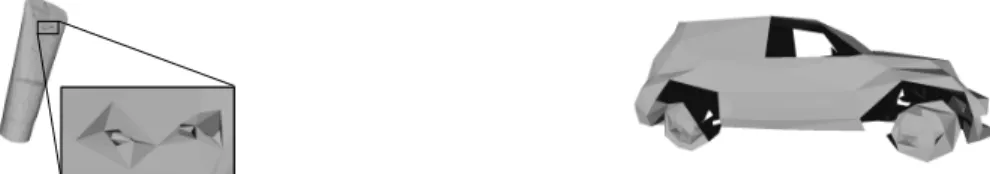
In particular, it is crucial to be able to know the fastest possible if a finger can not reach the object surface for a given grasp frame because we do not want to test all the

Nous avons proposé une heuristique constituée de trois phases : (1) la fixation de certaines variables par la résolution heuristique d’un problème de sac à dos avec contraintes

With generative methods, a DNN is trained to predict one (or multiple ordered) grasps from the sensor input. Predictions can be the direct regression of grasp parameters [6]

We show that amplitudes of the wrist acceleration peak (Experiment I), of the velocity and deceleration peaks (both experiments), and movement duration (Experiment I) were affected

The plenary keynotes and papers cover the wide spectrum of the topics related to Natural fibres and materials, Mechanical performances of bio-based building materials and design