Enhancing Infotainment Applications Quality of Service in Vehicular Ad Hoc Networks
par
Togou Mohammed Amine
Département d’informatique et de recherche opérationnelle Faculté des arts et des sciences
Thèse présentée à la Faculté des études supérieures en vue de l’obtention du grade de Philosophiæ Doctor (Ph.D.)
en informatique
Février, 2017
Les réseaux ad hoc de véhicules accueillent une multitude d’applications intéressantes. Parmi celles-ci, les applications d’infodivertissement visent à améliorer l’expérience des passagers. Ces applications ont des exigences rigides en termes de délai de livraison et de débit. De nombreuses approches ont été proposées pour assurer la qualité du service des dites applications. Elles sont réparties en deux couches : réseau et contrôle d’accès. Toutefois, ces méthodes présentent plusieurs lacunes.
Cette thèse a trois volets. Le premier aborde la question du routage dans le milieu urbain. A cet égard, un nouveau protocole, appelé SCRP, a été proposé. Il exploite l’in-formation sur la circulation des véhicules en temps réel pour créer des épines dorsales sur les routes et les connectées aux intersections à l’aide de nIJuds de pont. Ces derniers collectent des informations concernant la connectivité et le délai, utilisées pour choisir les chemins de routage ayant un délai de bout-en-bout faible. Le deuxième s’attaque au problème d’affectation des canaux de services afin d’augmenter le débit. A cet effet, un nouveau mécanisme, appelé ASSCH, a été conçu. ASSCH collecte des informations sur les canaux en temps réel et les donne à un modèle stochastique afin de prédire leur état dans l’avenir. Les canaux les moins encombrés sont sélectionnés pour être utilisés. Le dernier volet vise à proposer un modèle analytique pour examiner la performance du mécanisme EDCA de la norme IEEE 802.11p. Ce modèle tient en compte plusieurs facteurs, tels que l’opportunité de transmission, non exploitée dans IEEE 802.11p.
Mots clés: Réseaux ad hoc de véhicules, applications d’infodivertissement, routage (informatique), IEEE 802.11p (norme).
The fact that vehicular ad hoc network accommodates two types of communications, Vehicle-to-Vehicle and Vehicle-to-Infrastructure, has opened the door for a plethora of interesting applications to thrive. Some of these applications, known as infotainment ap-plications, focus on enhancing the passengers’ experience. They have rigid requirements in terms of delivery delay and throughput. Numerous approaches have been proposed, at medium access control and routing layers, to enhance the quality of service of such applications. However, existing schemes have several shortcomings. Subsequently, the design of new and efficient approaches is vital for the proper functioning of infotainment applications.
This work proposes three schemes. The first is a novel routing protocol, labeled SCRP. It leverages real-time vehicular traffic information to create backbones over road segments and connect them at intersections using bridge nodes. These nodes are re-sponsible for collecting connectivity and delay information, which are used to select routing paths with low end-to-end delay. The second is an altruistic service channel se-lection scheme, labeled ASSCH. It first collects real-time service channels information and feeds it to a stochastic model that predicts the state of these channels in the near future. The least congested channels are then selected to be used. The third is an ana-lytical model for the performance of the IEEE 802.11p Enhanced Distributed Channel Access mechanism that considers various factors, including the transmission opportunity (TXOP), unexploited by IEEE 802.11p.
RÉSUMÉ . . . ii
ABSTRACT . . . iii
CONTENTS . . . iv
LIST OF TABLES . . . viii
LIST OF FIGURES . . . ix LIST OF ABBREVIATIONS . . . xi NOTATION . . . xv DEDICATION . . . xvii ACKNOWLEDGMENTS . . . xviii CHAPTER 1: INTRODUCTION . . . 1 1.1 Research Context . . . 1 1.1.1 VANET Architecture . . . 2 1.1.2 VANET Characteristics . . . 3 1.1.3 VANET Challenges . . . 3 1.1.4 VANET Applications . . . 4
1.1.5 VANET Ongoing Projects . . . 6
1.2 Motivations and Objectives . . . 8
1.3 Thesis Contributions and Organization . . . 9
1.4 Thesis Organization . . . 11
CHAPTER 2: WIRELESS ACCESS FOR VEHICULAR ENVIRONMENT (WAVE) . . . 12
2.2.1 Physical Layer . . . 15 2.2.2 MAC Sublayer . . . 16 2.2.3 IEEE 1609.4 . . . 17 2.2.4 IEEE 1609.3 . . . 19 2.2.5 IEEE 1609.2 . . . 22 2.2.6 SAE J2735 . . . 23 2.3 Chapter Summary . . . 24
CHAPTER 3: RELATED WORK . . . 25
3.1 Routing in Urban VANET . . . 25
3.1.1 Node-Centric Routing Protocols . . . 26
3.1.2 Position-based Routing Protocols . . . 27
3.1.3 Limitation of Existing Routing Protocols . . . 29
3.2 DSRC Service Channel Selection . . . 31
3.2.1 Allocation-based Schemes . . . 31
3.2.2 Prediction-based Schemes . . . 33
3.2.3 Limitation of Existing SCH Selection Schemes . . . 34
3.3 IEEE 802.11p EDCA Performance Analysis . . . 35
3.3.1 EDCA Performance Analysis Considering TXOP . . . 37
3.4 Chapter Summary . . . 38
CHAPTER 4: SCRP: STABLE CDS-BASED ROUTING PROTOCOL FOR URBAN VEHICULAR AD HOC NETWORKS . . . 40
4.1 Problem Statement . . . 40
4.2 Network Model . . . 41
4.3 Stable CDS-based Routing Protocol . . . 42
4.3.1 Backbone Creation . . . 42
4.3.2 Link Lifetime Estimation (LLT) . . . 44
4.3.6 Route Construction . . . 53 4.4 SCRP Sensitivity Study . . . 54 4.4.1 Determining β . . . 54 4.4.2 Determining hmax . . . 55 4.4.3 Determining wth . . . 56 4.5 Performance evaluation . . . 57 4.5.1 Simulation settings . . . 58
4.5.2 Simulation Results and Analysis . . . 59
4.6 Chapter Summary . . . 63
CHAPTER 5: ALTRUISTIC SERVICE CHANNEL SELECTION SCHEME (ASSCH) FOR V2V INFOTAINMENT APPLICATIONS . 64 5.1 Problem Statement . . . 64
5.2 Network Model . . . 66
5.3 ASSCH Components . . . 67
5.3.1 SCHs State Information Collection . . . 67
5.3.2 SCHs Future State Prediction . . . 70
5.3.3 SCH Selection . . . 75 5.3.4 WBSS Termination . . . 77 5.4 Performance Evaluation . . . 78 5.4.1 Simulation Settings . . . 79 5.4.2 Simulation Results . . . 80 5.5 Chapter Summary . . . 84
CHAPTER 6: IEEE 802.11P EDCA PERFORMANCE ANALYSIS FOR INFOTAINMENT APPLICATIONS . . . 86
6.1 IEEE 802.11p EDCA Overview . . . 86
6.2 Assumptions and Notations . . . 87
6.3.3 Normalized Throughput . . . 95
6.3.4 Performance Evaluation . . . 96
6.4 IEEE 802.11p EDCA Performance Model Considering TXOP . . . 99
6.4.1 Probability of Transmission . . . 100
6.4.2 Normalized Throughput . . . 103
6.4.3 Performance Evaluation . . . 103
6.5 Chapter Summary . . . 106
CHAPTER 7: CONCLUSIONS AND PERSPECTIVES . . . 107
7.1 Conclusions . . . 107
7.2 Limitations . . . 108
7.3 Perspectives . . . 109
7.4 Future Research Direction . . . 110
7.5 Articles Published/Submitted . . . 110
2.I DSRC characteristics in USA, Japan, and Europe . . . 13
2.II EDCA Parameter set . . . 16
3.I Comparison of IEEE 802.11p EDCA Performance Analysis Models 37 4.I Simulation Parameter Settings . . . 58
5.I Simulation Parameter Settings . . . 79
6.I Notations’ definition . . . 88
6.II 1st Model Simulation Parameters . . . 97
1.1 RSU functionalities . . . 2
1.2 VANET applications . . . 5
2.1 DSRC channels . . . 12
2.2 WAVE protocol stack . . . 14
2.3 PPDU format . . . 15
2.4 IEEE 802.11p MAC architecture . . . 18
2.5 Alternating access mode: CCI followed by SCI . . . 19
2.6 WSM format . . . 20
2.7 WSA format . . . 21
3.1 Local maximum problem . . . 30
3.2 Data congestion problem . . . 30
3.3 Our solution for QoS support of infotainment applications in VANET 39 4.1 Backbone creation mechanism. . . 43
4.2 Bridge node selection mechanism . . . 45
4.3 Bridge node selection flowchart . . . 46
4.4 RAP format . . . 47
4.5 Connectivity and delay information collected via RAP . . . 49
4.6 Articulation junction selection procedure . . . 53
4.7 Determining the value of β . . . 55
4.8 Determining the value of hmax . . . 56
4.9 Determining the value of wth . . . 57
4.10 CDF of the links connectivity for (a) N = 200 and (b) N = 400 . . 59
4.11 Average E2ED vs. network density and packet generation rate . . 60
4.12 PDR vs. network density and packet generation rate . . . 61
4.13 Average routing overhead vs. network density . . . 62
5.4 WBSS overlapping problem . . . 76
5.5 WBSS setup and termination according to Amadeo et al. . . 78
5.6 WBSS setup and termination according to ASSCH . . . 78
5.7 Prediction accuracy rate vs. Number of providers . . . 80
5.8 Average capture delay vs. providers’ density . . . 82
5.9 Overlapping SCIs vs. number of providers . . . 83
5.10 Average throughput and collision rate vs. providers’ density . . . 84
6.1 The Markov chain modeling the backoff procedure of ACi . . . . 89
6.2 Contention zones for the different ACs . . . 92
6.3 The Markov chain modeling the contention phase of ACi . . . 93
6.4 Normalized throughput vs. traffic load . . . 97
6.5 Normalized throughput and success rate vs. number of providers . 98 6.6 Normalized throughput vs. packet size . . . 99
6.7 The Markov chain modeling the backoff procedure considering TXOP . . . 101
6.8 Normalized throughput vs. packet arrival rate . . . 104
6.9 Normalized throughput vs. number of stations per AC . . . 105
AC Access Category ACD Average Capture Delay
AES Advanced Encryption Standard AIFS Arbitrary Inter-Frame Spacing AODV Arbitrary Inter-Frame Spacing
AP Access Point
AVSI Advanced Vehicle Safety Initiative BSM Basic Safety Message
BSS Basic Service Set
BSSID Basic Service Set Identifier
CAHSI Cruise-Assist Highway System Initiative
CALM Continuous Air interface for Long and Medium distance CAR Connectivity Aware Routing
CBC-MAC Cipher Block Chaining Message Authentication Code CCH Control Channel
CCI Control Channel Interval CCW Channel Collision Warning
CDS Connected Dominating Set
CEPT European Conference of Postal and Telecommunications Administrations CH Cluster Head
CICAS Cooperative Intersection Collision Avoidance System CSMA/CA Carrier Sense Multiple Access/Collision Avoidance
DNS Domain Name System
DOT Department Of Transportation DS Distribution System
DSR Dynamic Source Routing
DSRC Dedicated Short Range Communication E2ED End-to-End Delay
ECIES Elliptic Curve Integrated Encryption Scheme EDCA Enhanced Distributed Channel Access
FCC Federal Communication Commission FI Frame Information
GI Guard Interval
GPS Geographic Positioning System GPSR Greedy Perimeter Stateless Routing GPCR Greedy Perimeter Coordinator Routing
GSR Geographic Source Routing HMM Hidden Markov Model
IEEE Institute of Electrical and Electronics Engineers ITS Intelligent Transportation Systems
LLC Logical Link Control LoS Line-of-Sight
MAC Medium Access Layer MANET Mobile Ad hoc Network
MCDS Minimum CDS
MDC Minimum Duration Counter
NOW Network on Wheels OBU On-Board Unit
OCB Outside the Context of BSS OCT Channel Occupancy Table
OFDM Orthogonal Frequency Division Multiplexing OSCHN Overlapping SCH Notification
PBR Position-based Routing PHY Physical Layer
PLCP Physical Layer Convergence Procedure PMD Physical Medium Dependent
PPDU Physical Protocol Data Unit PSC Provider Service Context PSDU PHY Service Data Unit
PSID Provider Service IDentifier QoS Quality of Service
RCPI Received Channel Power Indicator RREQ Route Request
RSSI Received Signal Strength Indication RSU Road Side Unit
RTS Ready To Send
SAE Society of Automotive Engineers SCH Service Channel
SCI Service Channel Interval SI Synchronization Interval SIFS Short Inter-Frame Space
TXOP Transmission Opportunity UTC Coordinated Universal Time V2V Vehicle-to-Vehicle
V2I Vehicle-to-Infrastructure VANET Vehicular Ad hoc Network
VII Vehicle Infrastructure Integration
VSC-A Vehicle Safety Communication Application VSS Vehicle-Based Safety Systems
WAVE Wireless Access for Vehicular Environment WBSS WAVE Basic Service Set
WEC World Energy Council WHO World Health Organization WILLWARN Wireless Local Danger Warning
WRA WAVE Routing Advertisement WSA WAVE Service Advertisement WSM WAVE Short Message
WSMP WAVE Short Message Protocol ZOR Zone of Relevance
SFi Stability Factor R Transmission Range
Vnb average speed of the tagged vehicle’s neighbors
dnb average distance between the tagged vehicle’s and its neighbors α , β weighting coefficients
tcross Time needed by a vehicle to cross the intersection zone
trem Remaining time of the green light phase tg Green light phase
ta Time to reach traffic light
tC Traffic light cycle
dp Delay to incur for transmitting a new data packet over a road segment dhi Delay to incur at each backbone vehicle
Tq Queuing delay Ttx Transmission delay drap RAP’s delivery delay
trx RAP’s received time
Tbc Time needed by RAP to travel a road segment with built-in backbone hmax Maximum number of backbone vehicles a road segment can hold
Tc f Maximum time to wait for RAP when using carry-and-forward wS
(i, j) Weight of road segment S(i, j)
dc f Delay to incur when using carry-and-forward l Cell’s length
lav Vehicle’s average length ds Average safety distance
vav Average speed of vehicles on Si, j
pc f Probability of using the carry-and-forward pcell Probability of having at least one vehicle in a cell λi Vehicles’ arrival rate at road segment Si, j
i, j
wpth Weight of the routing path
WV Ppth Weight validity period of the routing path wth Routing path weight threshold
SN Set of vehicles on SCH 172
piq Probability of a provider Pvirequesting a channel
Pm, j Probability that the channel will be in state Smin the next SCI given that it
is in state Sj
Pholdi Probability that provider Pviholds the same channel in the next SCI
Preleasei Probability that provider Pvi releases the channel at the end of the current
SCI
Pnrqi Probability that no provider of priority i requests the channel
Prq≥1i Probability that at least one provider of priority i requests the channel ti Time interval vehicles should wait before transmitting OSCHN
CWmin Minimum contention window CWmax Maximum contention window Ts Duration of a time slot
ri Retransmission limit
CWji Contention window size of ACiat backoff stage j
mi The backoff stage where CWmi = CWmaxi
pb Probability of a busy channel in a slot pci Collision probability of ACiin a slot
τi Transmission probability of ACi
psi Probability of successful transmission for ACi
pfi Probability of T X OPinot yet expired
TL Transmission time of a packet of size L
SISTERS, and BROTHER. I am forever indebted to you.
I would like to thank all the people who have encouraged me, in various ways, to pursue my goal. This dissertation would not have been possible without them.
My deep appreciation goes to Prof. Abdelhakim Hafid and Dr. Lyes Khoukhi for giving me the opportunity to work with them on one of the promising technologies that can make our world better. Their exemplary supervision, great support, valuable advice and constructive criticism have helped me become the researcher I am today.
Special thanks go to my PhD committee members, Prof. Hossam Hassanein, Prof. Rami Langar, Prof. Pierre Samuel, Prof. Philippe Langlais, and Prof. Dominique Gaiti for the constructive comments and suggestions, which helped improving the quality of the thesis.
I would like to thank Dr. Pratap Kumar Sahu for his guidance and encouragement during my first year as a Ph.D student. His explanations were easy to grasp and his feedback was highly appreciated. I am very glad to have worked with him.
I would like also to thank all my colleagues at LRC and ERA Research Laborato-ries for the beneficial discussions, research collaboration, and continuous exchange of knowledge. No doubt all LRC and ERA members are great people.
In addition, I would sincerely like to thank all my friends in Montreal, Canada and in Troyes, France, for their continuous support and encouragements. Special thanks for my brothers Mourad D’Himane and Mustapha Hrouga, who made my stay in Troyes comfortable and very enjoyable.
Last but not least, I would like to express my sincere gratitude to my family for their moral, financial, and never ending support for without them, none of this would have been possible.
INTRODUCTION
1.1 Research Context
Road safety and traffic efficiency are among the major problems that governments worldwide have been attempting to settle in the last decades. The inadequacy of current methods, i.e., post-crash measures (e.g., airbags) and road network expansion (i.e., due to spatial, financial, and environmental constraints), has mobilized government agen-cies and the automotive industry to develop prominent solutions that aim at making transportation systems safer and more efficient. The key idea is to equip vehicles with cutting-edge technologies (e.g., sensors, geographical positioning system (GPS), net-work interface cards (NICs), and cameras), making them evolve from a simple mean of transportation into intelligent systems that can assist drivers in making refined decisions and avoiding hazardous events. An example of such vehicles is KITT, David Hassel-hoff’s car in the Knight Rider (K2000) TV show (1982-1986).
When deployed, these vehicles shall enable a new self-configuring wireless network known as vehicular ad hoc network (VANET). It is based on the Wireless Access for Ve-hicular Environment (WAVE) standards suite and is considered as the key enabling tech-nology for future Intelligent Transportation Systems (ITS). VANET will enable several useful applications such as automatic road traffic alerts dissemination, dynamic route planning, service queries (e.g., parking availability), media sharing, and context-aware advertisement [1]. To provide such services, two communication modes are supported, including vehicle-to-vehicle (V2V) and vehicle-to-infrastructure (V2I).
In the next subsections, we start by briefly describing each communication mode. Then, we present the characteristics and challenges of VANET. Next, we describe VANET’s various applications and we review some of its ongoing projects.
1.1.1 VANET Architecture
VANET supports two forms of communication: to-infrastructure and vehicle-to-vehicle. In V2I, messages are exchanged between vehicles equipped with WAVE devices, called On-Board Units (OBUs), and stationary entities, called Road Side Units (RSUs), usually installed along road edges or in dedicated locations such as intersections and parking lots [2]. The basic functionality of RSUs is to extend the communication range of the vehicular network via relaying messages received from vehicles to other ve-hicles passing by (see Figure 1.1(a) [2]). They can also provide additional services such as real-time traffic statistics, weather forecast, and Internet access (see Figure 1.1(b) [2]).
(a) RSU as safety information provider
(b) RSU as Internet access provider
V2V is an infrastructure-less mode in which vehicles can directly communicate with one another when they are within transmission range (i.e., 300 to 1000 meters). They can also use multihop communication to reach out of range cars. At the heart of V2V is a basic technique, called beaconing. It consists of sending periodic messages, labeled beacons, containing various information such as vehicle’s position, speed, and direction. The goal of beaconing is to make vehicles aware of their neighboring vehicles’ current location in order to predict their future positions. This will help drivers make better decisions, avoiding therefore hazardous events.
1.1.2 VANET Characteristics
VANET has particular characteristics that distinguish it from other wireless net-works. For instance, nodes1 in VANET are highly mobile (i.e., up to 50 km/h in cities and 120 km/h in highways), causing frequent topological shifts. In addition, nodes movements are restricted by road layouts and shall abide to driving rules (e.g., traffic lights, stop signs, overtaking manoeuvres, etc.). Moreover, network density, which is directly linked to traffic flow, is observed to greatly fluctuate depending on time periods (i.e., night, day, and peak hours) as well as locations (i.e., downtown, highway, and sub-urban). Finally, VANET has no power nor computational capacity constraints. In fact, vehicles are equipped with batteries with a lifetime that spans between 3 to 5 years [3]. This allows for multiple gadgets to be installed such as high performance processors, high capacity memory cards, digital maps and GPS devices.
1.1.3 VANET Challenges
The aforementioned characteristics bring along new challenges that might affect the deployment of VANET in real life. For instance, high mobility and frequent topology shifts can lead to network fragmentation, resulting in sporadic connectivity. This forces routing protocols to build unstable routing paths that can extremely degrade the net-work’s quality of service (QoS), delay and throughput in particular. Moreover, VANET
has the potential to grow to a very large scale, imposing the need for new techniques (i.e., routing protocols, IP address configuration, and bandwidth allocation) as existing approaches for other wireless networks are not suitable for this highly agile environ-ment. Furthermore, maintaining a global network topology is nearly impossible for a node in VANET. Traditional structures like trees cannot be used since they incur high maintenance cost. Instead, each vehicle keeps track of its local topology information (i.e., number of neighboring nodes, their locations, and their speed), collected via peri-odic beacon messages. Besides, signal propagation between communicating vehicles is affected by the presence of obstacles (e.g., buildings, trees, and even vehicles), increas-ing therefore its fadincreas-ing rate [2]. Finally, security and privacy are of crucial importance to VANET. Since packets encapsulate critical information, it is mandatory to make sure that they are neither injected nor altered by fraudulent users. Keeping in mind the re-quirements of VANET environment, cryptographic algorithms along with authentication schemes must be as fast as possible to allow for real-time data transfer [4].
1.1.4 VANET Applications
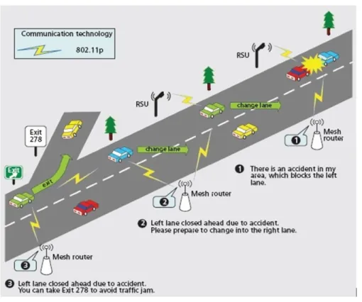
VANET was conceived primarily to enhance road safety and avoid accidents. Safety applications in VANET can be classified into event-driven and periodic, based on the frequency at which safety messages are transmitted. Event-driven applications require the transmission of safety messages only in case of an event taking place. For example, at intersections, messages regarding vehicles that are violating traffic lights or stop signs can be exchanged to prevent possible collisions. Similarly, in case of a car accident, mes-sages are broadcasted quickly into the accident’s vicinity urging drivers to slow down, averting therefore probable chain collisions (1 and 2 in Figure 1.2). These messages can also be used to notify vehicles near exits about the accident in order to avoid traffic jams (3 in Figure 1.2). Finally, paramedics and police officers can be notified immediately via RSUs to rapidly intervene and save people’s lives. Periodic safety applications, on the other hand, require transmission of safety messages at regular time intervals. To illus-trate, RSUs located at intersections can regularly notify approaching vehicles about road condition (e.g., slippery). They can also inform vehicles about the current traffic light
Figure 1.2: VANET applications
phase and the time remaining before switching to the next one. This information can be used by OBUs to suggest to drivers the stopping location or the optimal speed to cross the intersection without stopping at the traffic light.
Aside from safety-related applications, VANET allows for plenty of other services that offer tremendous potential for new business opportunities. These applications are of two types: traffic efficiency and infotainment. Traffic efficiency applications focus on enhancing route guidance and navigation. For instance, traffic statistics on various roads can be acquired in real-time and alternative routes can be provided to avoid traf-fic congestions. Likewise, controlling traftraf-fic lights via analyzing information collected through VANET (e.g., speed and density) can help smoothing traffic flows, therefore re-ducing traffic load on major roads. Infotainment applications, on the other hand, aims at improving the driving experience, making passengers’ journey more enjoyable. For example, available services in nearby regions (e.g., malls, restaurants, gas stations, and parking lots) can be advertised using RSUs. These RSUs can also provide Internet access
to passengers in order to check their emails, download music, or make online transac-tions. Finally, media sharing (e.g., music, movies), social media applications, and online multiplayer games can be enabled between neighboring vehicles. Bear in mind that these applications may accelerate the deployment of VANET since people are more and more addicted to their smartphones and they want to be connected anywhere, anytime.
1.1.5 VANET Ongoing Projects
Since the early 90s, VANET activity in terms of research and development has been intensively growing. In this regard, several projects that aim at ensuring road safety have been jointly launched by governmental agencies and car manufacturers in different parts of the world. In the United States, the Federal Communication Commission (FCC) assigned 75 MHz bandwidth from the 5.9 GHz band as a freely licensed spectrum to enable safety applications using Dedicated Short Range Communication (DSRC) [5]. Since then, several projects have seen light. For instance, Vehicle Infrastructure Integra-tion (VII), rebranded to IntelliDrive, focuses on establishing test beds to provide support for V2V and V2I under DSRC. It also studies non-technical issues regarding privacy, liability, and application of regulations. Similarly, the Vehicle Safety Communication-Application project (VSC-A) focuses on vehicle communication and relative position-ing, with the goal of enabling interoperability among safety applications [6]. It identifies eight crash scenarios, including Emergency Electronic Brake Lights (EEBL), Forward Collision Warning (FCW), Blind Spot Warning (BSW), Intersection Movement Assist (IMA), and Do Not Pass Warning (DNP). The Integrated Vehicle-Based Safety Systems (IVBSS) project explores the human-machine interface issues when several safety appli-cations, with potentially overlapping or contradictory advisories, are operated simulta-neously [6]. Finally, the Cooperative Intersection Collision Avoidance System (CICAS) focuses on preventing dangers at intersections by allowing traffic lights to transmit phase and timing information to nearby vehicles. Each vehicle would then predict the likeli-hood of violating the red light; drivers are notified only when needed.
In Japan, a standard for V2I communication denoted also as DSRC System was issued in 2001. It was used in electronic toll collection, but the system was generalized to
support various services [6]. With the great success that this system has known, various ITS projects have been inaugurated to enhance V2I and V2V communications under the umbrella of Japan’s national ITS Safety 2010 initiative. For example, the Advanced Vehicle Safety Initiative (AVSI) aims at warning drivers against road dangers ahead and preventing rear-end collisions. It also focuses on developing new techniques for position recognition of neighboring vehicles using V2V communication based on the Carrier Sense Multiple Access (CSMA) technology [6]. The Advanced Cruise-Assist Highway System (AHS) initiative focuses on reducing traffic accidents, enhancing safety, and improving transportation efficiency using RSUs.
In Europe, a 30 MHz bandwidth was allocated by the European Conference of Postal and Telecommunications Administrations (CEPT) to support road safety services [7]. Since then, several projects were initiated. Examples include COOPERS, CVIS, SAFESPOT, and PReVENT. The Co-operative Systems for Intelligent Road Safety project (COOPERS) focuses on developing innovative applications for cooperative traffic man-agement using V2I communication. It makes use of Continuous Air interface for Long and Medium distance (CALM) standards, aiming at supporting continuous communi-cations between vehicles via employing various media and communication interfaces [6]. The Co-operative Vehicle-Infrastructure Systems project (CVIS) aims at design-ing, developdesign-ing, and testing new technologies to enable V2V and V2I communications following the CALM standards. It also makes use of the IEEE 802.11p interface, de-noted as "Microwave 5 GHz" (M5) interface [6]. The SAFESPOT project focuses on enhancing the field’s view of autonomous vehicles via developing sophisticated coop-erative systems that are based on V2V and V2I communications. The communication technology used in SAFESPOT is IEEE 802.11a/p [6]. Finally, the Preventive and Ac-tive Safety Applications project (PReVENT) aims at developing, testing, and evaluat-ing safety related applications usevaluat-ing advanced sensevaluat-ing and communication devices in-tegrated in OBUs. Within PReVENT, the Wireless Local Danger Warning subproject (WILLWARN) is based on IEEE 802.11a/p and uses the Network on Wheels (NOW) [8] communication platform.
1.2 Motivations and Objectives
Infotainment applications are supported by WAVE in order to accelerate VANET’s deployment. Most of these applications have rigid QoS requirements (i.e., bandwidth, delay and throughput). Yet, meeting them is not straightforward, given the particular characteristics of VANET (e.g., high mobility, sporadic connectivity, and short links life-time). Thus, the objective of this dissertation is to design and evaluate new solutions to ensure infotainment applications QoS. This is done at the network layer and the medium access control (MAC) sublayer. On the one hand, we propose a new routing protocol for infotainment applications that considers the end-to-end delay when forwarding data packets. On the other hand, we design and implement new mechanisms for managing re-sources, DSRC channels in particular, in order to enable service differentiation between different infotainment applications to further enhance their QoS.
The first part of this thesis addresses the problem of routing in urban VANET con-sidering infotainment applications QoS requirements (e.g., short delivery delay and low packet loss ratio). Several routing strategies have been proposed to deal with this issue. Among them, position-based routing (PBR) ought to be the most convenient as it ex-hibits great resilience to network topology changes [9]. Various PBR schemes [10–21] have been proposed in the literature. They are either reactive or proactive. Reactive schemes aim at establishing routing paths whenever a data packet is to be transmitted while proactive approaches build virtual infrastructures (e.g., clusters and backbones), ahead of time, to relay messages. Despite their good performance, exiting schemes sustain major shortcomings. On the one hand, reactive protocols only acquire local net-work topology, making them prone to local maximum and data congestion problems (see Chapter 4 for more details). Proactive protocols, on the other hand, suffer large control message overhead when maintaining the infrastructure, which might lead to network congestion.
The second part of this dissertation focuses on the problem of DSRC channel se-lection to enhance the QoS of V2V infotainment applications. In the literature, several schemes [22–34] have been proposed to help service providers, mainly vehicles, of
info-tainment applications select service channels that guarantee the best QoS (e.g., through-put). They can be of two types: allocation-based and prediction-based. The former uses single or dual transceivers and requires vehicles to keep track of used service channels in their 1-hop and 2-hop ranges. This information is then exchanged on an event-driven ba-sis and is used to select the least congested channel. The latter uses multiple transceivers to continuously monitor all channels and deploys prediction mechanisms to identify the best channel to be used. Although they assure certain level of QoS, schemes in both categories experience various limitations. On the one hand, channel occupancy informa-tion may be obsolete due to collisions, rendering the existing allocainforma-tion-based schemes of limited value. On the other hand, prediction-based schemes suffer cross-channel in-terferences and are cost-inefficient, due to the use of multiple transceivers, making them infeasible, particularly during VANET’s initial deployment [35].
The final part of this thesis addresses the problem of accurately modeling the per-formance of the enhanced distributed access channel (EDCA) mechanism for IEEE 802.11p. This problem shall take into account many criteria, including the saturation condition, the backoff procedure, the internal/external collisions, and the transmission opportunity (TXOP). Several models [36–42] have been proposed in the literature to an-alyze the IEEE 802.11p EDCA performance. While most of them were designed for safety applications, very few can be applied to non-safety applications. Yet, to the best of our knowledge, none of the proposed models have considered all the aforementioned factors.
1.3 Thesis Contributions and Organization
The aforementioned research topics have yielded several results that we have sub-mitted or published as articles in international refereed journals and conferences. The thesis consists of three contributions made from three scientific articles (two journal ar-ticle and one conference paper) which we considered the most significant and complete among the seven articles proposed. Four of these articles are already published (one journal article and three conference papers), two conference papers are accepted, and
one journal article is under review (minor revision).
To address the issue of routing in urban VANET, we proposes a novel routing pro-tocol SCRP [43, 44]. It is a distributed geographic source routing scheme that takes advantage of the network topology to select routing paths with low end-to-end delay (E2ED). SCRP starts by building backbones over road segments considering vehicles’ speed and spatial distribution. These backbones are then connected at intersections via bridge nodes that keep an up-to-date network topology while monitoring the delay to incur for transmitting new data packets over road segments. Based on this information, SCRP assigns weights to road segments; the ones with the lowest weights are selected to construct routing paths.
We then describe the service channel selection mechanism, called Altruistic Service Channel Selection Scheme (ASSCH), a hybrid approach that aims at improving V2V in-fotainment applications performance without affecting the delivery of safety messages. It is WAVE-compliant and has three phases: 1) collecting real-time information about channels state via compelling vehicles to collaborate; 2) feeding the collected informa-tion to a Markovian model that predicts the state of each channel in the near future; and 3) selecting the least congested/used channel.
Finally, we present a theoretical and simulation-based analysis of the IEEE 802.11p EDCA mechanism. In this regard, two Markovian models are proposed, taking into consideration various factors (e.g., saturation condition, the backoff procedure, the in-ternal/external collisions). The first model describes the backoff procedure as well as the contention phase of the different traffic classes. The second model [45] extends the first one by considering TXOP, unexploited by IEEE 802.11p. Using both models, we derive the probability of transmission and the probability of collision and we infer the normalized throughput for each traffic class. Simulations were conducted to verify the effectiveness of our analysis.
1.4 Thesis Organization
The remaining of this dissertation is structured as follows. After introducing VANET and its characteristics, we review the WAVE framework in chapter 2. We describe in de-tails the different standards being developed for WAVE deployment in the United States, including the IEEE 802.11p standard, the IEEE 1609.X standards family, and the SAE J2735 Message set Dictionary. In Chapter 3, we outline the existing approaches in the literature that address the aforementioned issues (i.e., routing in urban VANET, DSRC channel allocation, and EDCA performance modeling). We then present SCRP in chap-ter 4, describe ASSCH in chapchap-ter 5, and detail the models proposed for IEEE 802.11p EDCA performance analysis in chapter 6. Finally, in chapter 7, we summarize the major contributions of this dissertation, outline future research directions, and present the list of articles produced during this thesis.
WIRELESS ACCESS FOR VEHICULAR ENVIRONMENT (WAVE)
The automotive industry has been working to develop WAVE framework, which will be used to support both V2V and V2I. The effectiveness of this technology is highly dependent on cooperative standards for interoperability [5]. In this chapter, we aim at giving insights about the different technologies and standards being developed for WAVE deployment. This includes the Dedicated Short Range Communication (DSRC) technology; the IEEE 802.11p standard; IEEE 1609.2, 1609.3, 1609.4 standards for Se-curity, Network Services, and Multichannel Operations; and the SAE J2735 Message Set Dictionary. Although WAVE is of interest to several countries, implementation models vary from one place to another. In the following sections, we shed light on the North American version of WAVE.
The rest of the chapter is organized as follows. Section 2.1 gives an overview of DSRC while Section 2.2 describes in details WAVE’s protocol stack. Section 2.3 con-cludes the chapter.
2.1 DSRC Overview
In 1999, the U.S FCC has allocated 75 MHz of licensed spectrum in the 5.9 GHz band (i.e., from 5.85 GHz to 5.925 GHz) for DSRC communication [5]. This spectrum is divided into seven 10 MHz channels, as illustrated in Figure 2.1, and a 5 MHz guard band. Channels 172 and 184 are reserved for public safety applications. Channel 178 is referred to as the Control Channel (CCH) and is exclusively dedicated to transmitting
safety and control messages. The remaining channels are referred to as Service Channels (SCHs) and are used for transmitting data packets of infotainment applications. Table 2.I [5, 46] shows DSRC characteristics in USA, Japan, and Europe.
Table 2.I: DSRC characteristics in USA, Japan, and Europe
Features USA Japan Europe
Communication Half-duplex Half-duplex (OBU)
full-duplex (RSU) Half-duplex
Band 75 MHz 80 MHz 30 MHz
Channels 7 Downlink: 7, Uplink: 7 4
Transmission range 1000 m 30 m 15-20 m
Data Rate 3-27 Mbps 1, 4 Mbps 250-500 Kbps
Radio frequency 5.9 GHz 5.8 GHz 5.8 GHz
Channel separation 10 MHz 5 MHz 5 MHz
The primary motivation behind developing DSRC is to enable collision prevention applications. Indeed, the U.S Department of Transportation (DOT) has estimated that V2V communications based on DSRC can address up to 82% of all crashes in the United States involving unimpaired drivers, potentially saving thousands of lives and billions of dollars [5]. The reason is twofold: 1) DSRC is based on short-range (i.e., hundreds of meters) two-way Line-of-Sight (LoS) communication with sufficient bandwidth which is significantly cheap compared to other technologies such as cellular, WiMax or Satellite [35]; and 2) DSRC adopts WiFi standards, making operations related to V2V and V2I easier to integrate and implement.
DSRC can also be pivotal for many other applications beyond collision prevention. Most of these involve communication to and from RSUs [5]. For instance, DSRC can be used to assist navigation, make electronic payments (e.g., tolls, parking), reduce fuel consumption (i.e., reducing therefore CO2 emissions), as well as collecting real-time
traffic statistics and disseminating them. It can also be used for entertainment purposes such as Internet access, media sharing, and online gaming.
2.2 WAVE Standards Suite
Figure 2.2 [5] illustrates WAVE protocol stack. The physical and MAC layers are based on the IEEE 802.11p standard, which is a modified version of IEEE 802.11. At the upper layers, WAVE employs a suite of standards defined by the IEEE 1609 Working Group to enable safety applications: 1609.4 for multichannel operations, 1609.3 for net-work services (i.e., including WAVE Short Message Protocol (WSMP)), and 1609.2 for security services. Non-safety applications, on the other hand, use IPv6 and the TCP/UDP protocols in the network and transport layers, respectively. In the next subsections, we examine in more details the different standards, working from bottom to top.
2.2.1 Physical Layer
WAVE’s physical layer is based on the IEEE 802.11a standard. It uses Orthogonal Frequency Division Multiplexing (OFDM) modulation to provide different data rates (i.e., from 3 to 27 Mbps) and has two modules.
2.2.1.1 Physical Layer Convergence Procedure (PLCP)
At the transmitter, PLCP processes the bytes in a MAC frame to be transformed into OFDM symbols for transmission over the air by Physical Medium Dependent (PMD) module [5]. PLCP adds the physical layer overhead to the MAC frame to create a Physi-cal Protocol Data Unit (PPDU), as illustrated in Figure 2.3 [47]. The Preamble is used to synchronize the signal at the receiver. while the SIGNAL field contains the data rate and the frame length, acquired from the MAC layer. The SERVICE and TAIL fields facilitate bit scrambling whereas the PAD field enures that the final OFDM symbol is properly encoded. The Physical Layer Service Data Unit (PSDU) field contains the MAC frame. At the receiver, PLCP performs the inverse function to extract the MAC frame from the PPDU. It also provides the Received Signal Strength Indication (RSSI) to the MAC layer.
2.2.1.2 Physical Medium Dependent (PMD) Function
When PMD receives PPDU from PLCP, it performs OFDM modulation and trans-mits PPDU over the air. At the receiver, PMD performs demodulation and passes the received PPDU to PLCP along with RSSI. Note that, unlike IEEE 802.11a, DSRC uses 10 MHz channels to account for delay and Doppler spreads, likely to be encountered in the vehicular environment [48].
2.2.2 MAC Sublayer
Like IEEE 802.11, IEEE 802.11p uses Carrier Sense Multiple Access/Collision Avoid-ance (CSMA/CA) as the medium access mechanism. In addition, IEEE 802.11p utilizes the Enhanced Distributed Channel Access (EDCA) mechanism to provide service dif-ferentiation. In this paradigm, four access categories (ACs) are defined (i.e., AC_BK, AC_BE, AC_VI, and AC_VO), each having its own parameters (i.e., Arbitration Inter-Frame Space (AIFS), minimum contention window (CWmin) and maximum contention
window (CWmax)) with AC_VO having the highest priority, as show in Table 2.II. aCWmin
and aCWmax are set to 15 and 1023, respectively [47].
Table 2.II: EDCA Parameter set
AC CWmin CWmax AIFSN TXOP
AC_BK aCWmin aCWmax 9 0
AC_BE aCWmin aCWmax 6 0
AC_VI aCWmin+1
2 − 1 aCWmin 3 0
AC_VO aCWmin+1
4 − 1
aCWmin+1
2 − 1 2 0
Each AC, with a frame to transmit, senses the channel first. If the channel is idle and stays idle for at least AIFS, AC starts transmitting its frame. If the channel is busy, AC invokes the backoff procedure by choosing a number of idle time slots (AIFSN) to wait before attempting to transmit its frame. The countdown begins when the channel becomes idle, is interrupted during any non-idle interval, and resumes when the medium stays idle for at least AIFS [5]. Once AC transmits its unicast frame, it waits for an
acknowledgement (ACK) from the recipient. If ACK is not received within a timeout interval, AC retransmits the frame after invoking the backoff process. A frame can be retransmitted as long as the retransmission limit is not yet reached. In case of unsuccess-ful retransmission given that the retransmission limit was attained, the frame is dropped. Note that each AC is allowed to send only one frame per channel access, i.e., transmis-sion opportunity (TXOP) of each AC is set to 0.
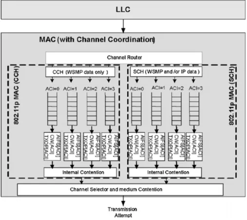
The channel router module, illustrated in the top of Figure 2.4 [35], inserts data frames into ACs of the appropriate channel based on the channel identifier and the prior-ity fields, contained in their headers. Data frames will then be dequeued and scheduled for external contention depending on their AC indices. The channel selector module, depicted in the bottom of Figure 2.4, is responsible for carrying out multiple decisions such as when to monitor a specific channel and for how long.
Besides, IEEE 802.11p introduces some enhancements to the traditional IEEE 802.11 standard in order to cope with VANET high mobility. Indeed, IEEE 802.11p defines a new type of communication, called Outside Context of Basic Service Set (OCB), partic-ularly for V2V, where exchanging data frames does not require neither authentication nor association. To distinguish frames sent in OCB mode, IEEE 802.11p sets the value of BSSID field in the frame header to 0xFFFFFF, also known as the wildcard value. A receiver with OCB mode enabled will pass up the stack any data frame that has the wildcard value as BSSID and will ignore any data frame with different BSSID. Data frames sent in OCB mode are transmitted between nodes that do not belong to any Basic Service Set (BSS). IEEE 802.11p defines the context of having such exchange as WAVE BSS (WBSS), which will be investigated in chapter 5. In addition, IEEE 802.11p intro-duces a new management frame, labeled Timing Advertisement (TA), which can be used to distribute time synchronization information [49] in the absence of GPS devices.
2.2.3 IEEE 1609.4
IEEE 1609.4 defines a management extension to IEEE 802.11p that enables DSRC devices to switch between different channels (i.e., CCH and SCHs). Under this exten-sion, IEEE 1609.4 maintains a separate logical instance of the IEEE 802.11p MAC,
Figure 2.4: IEEE 802.11p MAC architecture
including EDCA and state variables, for each channel on which it operates [5].
WAVE defines three types of devices: single transceiver (i.e., can only be on one channel at a time), dual transceivers (i.e., one is dedicated to CCH while the other switches between SCHs), and multi-transceivers (i.e., having a transceiver for each chan-nel). The goal of IEEE 1609.4 is to specify a mechanism that allows all WAVE devices to communicate. In this regard, IEEE 1609.4 defines two channel access modes: 1) continuous, where CCH and SCHs are constantly monitored (i.e., the case of dual and multi-transceiver devices); and 2) alternating, which uses Coordinated Universal Time (UTC), obtained from GPS signals, to define a time division concept as illustrated in Figure 2.5 [5]. Indeed, each second is divided into ten Synchronization Intervals (SIs). Each SI consists of one Control Channel Interval (CCI) followed by one Service Channel Interval (SCI). Guard Intervals (GIs) are inserted at the end of each CCI/SCI to account for synchronization imprecisions [49]. When using the alternating mode, vehicles shall
monitor CCH during CCI to not miss safety messages, and can switch to one of SCHs during SCI.
Figure 2.5: Alternating access mode: CCI followed by SCI
2.2.4 IEEE 1609.3
IEEE 1609.3 defines a new protocol, called WAVE Short Message Protocol (WSMP), considered efficient for 1-hop transmission of safety messages since it avoids the packet overhead associated with conventional internet protocols. Packets sent using WSMP are called WAVE Short Messages (WSMs). The minimum WSM overhead is 5 bytes, and will rarely exceed 20 bytes, options and extensions included. This makes WSMP of great value given WAVE’s pivotal concern (i.e., channel congestion).
2.2.4.1 Wave Short Message
WSM format is depicted in Figure 2.6 [5]. It consists of variable-length header followed by variable-length payload and includes both mandatory and optional fields.
The WSM Version field indicates the version number associated with the current 1609.3 standard, which is 3 [50].The Provider Service Identifier (PSID) field plays a similar role as a TCP/UDP port. It identifies the service that WSM payload is associ-ated with. For bandwidth efficiency, PSID is defined in variable-length format. Leading bits are used to indicate the number of bytes in PSID. For instance, a leading bit of 0
Figure 2.6: WSM format
indicates that PSID is 1-byte long while a leading bit of 01, 011, and 0111 indicate that PSID is 2-bytes, 3-bytes, and 4-bytes long, respectively.
The Extension Fields are optional fields used for future extensibility. IEEE 1609.3 defines 4 extension fields: channel number, data rate, transmit power used, and channel load. Each one of these extensions has three attributes: identifier byte), length (1-bytes), and content (1-byte) [50]. The WSM WAVE Element ID field is used to identify extensions contained in WSM header [50] while the Length field indicates the length of the payload. The range of values for WSM length is 1 to W smMaxLength − h, where h is the length of WSM header. Finally, WSM Data field contains the higher layer infor-mation being transferred.
2.2.4.2 Wave Service Advertisement (WSA)
IEEE 1609.3 defines another type of messages, labeled WSA. It contains information regarding services to be offered by WAVE devices. A service can be almost any exchange of information that provides value to a vehicle’s occupants [5]. Traffic alerts, tolling, navigation, parking availability, and Internet access are few examples among many. Most services are provided by RSUs, but vehicles could also cater services. Keep in mind that safety messages are not considered as a service and therefore are not announced via WSA.
Figure 2.7: WSA format
WSAs are broadcasted over CCH. This is to make all vehicles in an area aware of the existing services. These services can be offered on one or more SCHs. Indeed, a WSA-sender, labeled provider, may offer up to 32 services, which can all be advertised with a single WSA. These services can be supported by IPv6 or WSMP. When hearing WSAs, vehicles interested in the advertised services, labeled users, switch to the appropriate SCHs at the beginning of SCI.
The format of WSA message is shown in Figure 2.7 [47]. The WSA Version field shall be 3 for the current 1609.3 standard [50]. The Header Option Indicator field in-dicates which optional fields (i.e., the shaded fields) are present in WSA. A value of 1 in the ith bit implies that the ith optional field is present. The WSA Identifier field is an unsigned integer, between 0 and 15, used to uniquely identify each WSA. The Content Countfield is used by the recipient to determine whether the received WSA is a repeat of a previously received WSA (i.e., case of persistent WBSS, defined in Chapter 5). The WAVE Information Element Extension field has the same format as extension fields in WSM (i.e., identifier, length, and content). It defines five extensions: Repeat Rate, indicating the number of times WSA is transmitted per 5s; transmit power used, indi-cating the power with which the WSA frame was transmitted; 2DLocation; 3DLocation, considering elevation; and Advertiser Identifier.
The Service Info Segment field describes the services being offered (up to 32 in-stances). Each service instance has ten fields: 1) PSID; 2) Channel Index: indicates SCH where the advertised service will be offered; 3) Service Info Option Indicator: indicates the presence of Service Info WAVE Information Element Extension field if set to 1; 4)
Service Info WAVE Information Element Extension: provides supplementary informa-tion about the service; 5) IPv6 Address; 6) Service Port; 7) Provider MAC Address; 8) Received Channel Power Indicator (RCPI) Threshold: indicates the recommended min-imum received WSA signal value below which the service should be ignored; 9) WSA Count Threshold: indicates the recommended minimum number of received WSAs be-low which the service should be ignored; and 10) WSA Count Threshold interval: indi-cated the time interval over which received WSAs are counted. It is optionally used with WSA count threshold.
The Channel Info Segment field provides information regarding channels on which services are being offered. There can be up to 32 instances of channel info, each hav-ing seven fields: 1) Operathav-ing Class: allows the channel number to uniquely identify a specific channel in the context of a country; 2) Channel Number; 3) Transmit Power Level; 4) Adaptable: indicates whether Data Rate is a boundary or fixed value; 5) Data Rate; 6) Channel Info Option Indicator: indicates the presence of Channel Info WAVE Information Element Extension field if set to 1; and 7) Channel Info WAVE Informa-tion Element Extension, which has two fields: a) EDCA Parameter Set; and b) Channel Access, indicating the time slots during which the provider will be on the associated channel.
Finally, the WAVE Routing Advertisement (WRA) field is used when the provider offers a service that utilizes IPv6. It provides information to users about how to connect to the Internet. Each WSA includes one WRA at most. WRA has the following fields: 1) Router Lifetime: indicates the duration during which the Default Gateway is valid; 2) IP Prefix: indicates the IPv6 subnet prefix; 3) Prefix Length; 4) Default Gateway; 5) Primary Domain Name System (DNS); and 6) WRA optional WAVE Information Element Extension, which contains secondary DNS and Gateway MAC Address fields.
2.2.5 IEEE 1609.2
IEEE 1609.2 uses certificates to authenticate messages. These certificates include information such as the public key of the sender, the permissions associated with that public key, the identifier of the issuer, information to determine whether or not the
cer-tificate has been revoked, the region within which the cercer-tificate is valid (i.e., mainly for RSUs), the validity period, and the services that the certificate holder is allowed to provide [51]. Vehicles will typically be reloaded with new certificates infrequently (i.e., each year). These certificates can be used for a limited time (e.g., 5 to 10 minutes) [5], so that vehicles’ movements cannot be easily tracked using their safety messages broadcast over long intervals [5]. For bandwidth efficiency purposes, once certificates are exchanged between vehicles, only certificate digests can be appended to WSMs.
Besides, IEEE 1609.2 defines an encryption algorithm that uses a combination of symmetric and asymmetric cryptography. The symmetric algorithm is Advanced En-cryption Standard (AES) with 128-bit keys in Counter CBC-MIC mode while Elliptic Curve Integrated Encryption Scheme (ECIES) is the asymmetric algorithm [52]. The sender will encrypt the message with a symmetric key, and then will encrypt the sym-metric key using the asymsym-metric algorithm [5]. The receiver will decrypt the symsym-metric key first then the message.
2.2.6 SAE J2735
This SAE standard specifies a list of message types that are to be used by VANET applications [53]. Each message is defined as a collection of data structures, called data elements and data frames. A data element is the most basic structure in SAE J2735 standard. A data frame, on the other hand, is a complex data structure, composed of one or more data elements or other data frames [53]. SAE J2735 standard defines the syntax (i.e., length and format) and semantics of each data element and data frame.
One of the most important messages in SAE J2735 standard is the Basic Safety Message (BSM). It conveys vehicle state information necessary to support V2V safety applications. It has also the flexibility to convey additional information, as required by the application [5]. BSM has two parts. Part I includes critical state information that must be sent in every BSM (e.g., position, dynamics, direction, system status, and size). Part II is optional and can be tailored to applications’ needs.
2.3 Chapter Summary
WAVE has the capacity to support various types of applications, including infotain-ment applications that offer new business opportunities. WAVE relies on several stan-dards (e.g. DSRC, IEEE 802.11p, IEEE 1609.4, IEEE 1609.3, and IEEE 1609.2), and basic interoperability tests among independent WAVE implementations are encouraging [54]. Still, a number of challenges remain. Among them, an efficient mechanism to select the best service channel to be used by service providers (i.e., mainly vehicles) is needed. This is addressed in chapter 5. In addition, the fact that IEEE 802.11p EDCA sets TXOP of all ACs to 0 deprives infotainment applications, especially those using high priority ACs (i.e., AC_VO, AC_VI), from efficiently using service channels. This problem is tackled in chapter 6. Finally, the harmonization of standards between the United States and other regions of the world shall be performed to promote fast market penetration.
RELATED WORK
Many schemes have been proposed to address the problem of QoS assurance in the context of vehicular ad hoc networks. They are divided into networking layer approaches and MAC layer techniques. The first part of this chapter describes the routing challenges facing VANET in urban settings and presents the different routing protocols that have been designed to tackle those issues. Afterwards, we describe how data packets of V2V infotainment applications are transmitted following the WAVE framework and review existing mechanisms that enable providers selecting the least congested service channels. Finally, we outline the distinctive factors that shall be considered when analyzing the performance of the IEEE 802.11p EDCA mechanism and surveys the different models proposed in this regard.
3.1 Routing in Urban VANET
The urban environment poses a series of technical challenges to VANET’s routing. Estimating the exact number of vehicles on road segments is complicated since traffic density fluctuates considerably from downtown to suburbs and from day to night. In addition, vehicles’ spatial distribution over road segments can be uneven as vehicles tend to pile up at intersections, leading to sporadic connectivity. Furthermore, the presence of obstacles (e.g., buildings, trees, and large vehicles) blocks signal propagation between neighboring vehicles, making of intersections the ultimate point for routing decisions. To address these issues, extensive research has been carried out. The following subsection reviews some of the well known routing protocols in the literature designed for VANET in urban settings.
3.1.1 Node-Centric Routing Protocols
The first attempt to solve the issue of routing in urban VANET was the deployment of node-centric routing protocols designed mainly for mobile ad hoc networks (MANETs). MANET is a self-configuring type of wireless networks in which communication be-tween mobile nodes (i.e., low to moderate mobility) can be carried out without reliance on centralized resources or fixed infrastructure. A well known MANET routing protocol is Ad-hoc On Demand Distance Vector (AODV) [55]. AODV creates routes between nodes only when they are requested by source nodes. Indeed, Route Request (RREQ) packets are flooded through the network in order to create routing paths to destination nodes. RREQ contains the source IP address, the source node’s sequence number, the destination IP address, and the destination node’s sequence number. Sequence numbers are used to maintain the consistency of the routing information (i.e., routing tables). Routes remain active as long as source nodes transmit periodic "Hello" messages. In case "Hello" messages are no more received, routes time out and are deleted from the routing tables.
Still, due to nodes’ high mobility, MANET protocols seem to be unsuitable for VANET. In fact, the experimental study presented in [56] showed that AODV was un-able to maintain long routes in VANET and suffered large packet losses along with high end-to-end delay. Consequently, MANET protocols had to be customized to become VANET-compliant. Namboodiri et al. [57] proposed PRAODV, which uses vehicles’ speed and location information to predict links’ lifetime and constructs alternative routes before links expire. Since PRAODV selects the shortest alternative path, which may not always be the best solution, a modified version called PRAODV-M was also presented in [57] in order to select the path with the maximum predicted lifetime. Ooi et al. [58], on the other hand, studied AODV’s RREQ flooding and concluded that it can definitely cause network congestion in VANET. Subsequently, they proposed that RREQ messages can only be forwarded within a limited zone, called Zone of Relevance (ZOR) (i.e., an example of ZOR is the vicinity of a car crash).
node-centric schemes still have poor performance in various VANET settings. As a result, they are no longer used. Several routing strategies have been developed specifically for the adverse environment of VANET. Among them, position-based routing (PBR) [9] ought to be the most convenient routing approach for urban VANET as it exhibits great resilience to network topology. It requires each vehicle to periodically broadcast its position via beacon messages. This is feasible nowadays as most vehicles are equipped with GPS devices. To attest for PBR convenience, projects such as CarTALK2000 [60] and NOW [8] have already deployed it.
3.1.2 Position-based Routing Protocols
Various position-based routing protocols have been designed to address the routing issues in urban VANET. One of the well-known schemes is Greedy Perimeter Stateless Routing (GPSR) [10]. It combines greedy forwarding, by sending packets to the closest neighbor to the destination, with perimeter routing, a sequence of edges traversed using the right hand rule in order to go around void regions. Despite its good performance in highway scenarios, studies such as [12] and [13] have shown that GPSR suffers from sever performance degradation in urban environments. This is because: 1) direct com-munication between nodes may not be possible due to obstacles (e.g., buildings); and 2) frequent topology changes may induce routing loops. This implies that packets might get forwarded in the wrong direction, yielding high delivery delay.
To address these shortcomings, several anchor-based protocols have been proposed. Lochert et al. proposed Geographic Source Routing (GSR) [11] and Greedy Perimeter Coordinator Routing (GPCR) [12]. GSR combines static street maps with Dijkstra’s algorithm to compute the shortest distance path, expressed as a list of intersections, be-tween source and destination. Like GSR, GPCR also computes the shortest distance path between source and destination. However, instead of using static street maps like GSR, GPCR only exploits local information obtained via beacon messages. Indeed, GPCR always forwards packets to nodes at intersections, called coordinators, responsible for making routing decisions (i.e., shortest path to destination) since they have better net-work visibility. Still, due to their lack of traffic-awareness, both GSR and GPCR are
highly susceptible to network fragmentation as the distribution of vehicles on road seg-ments is uneven.
Subsequently, traffic-aware routing schemes have emerged. Lui et al. [13] proposed Anchor-based Street and Traffic Aware Routing (A-STAR) protocol. It combines street maps with statically or dynamically rated maps. These maps show the number of city buses going through each street statically or based on the current traffic state, and are used to identify the sequence of intersections, labeled anchors, through which packets might be forwarded. In case an anchor gets disconnected, A-STAR marks it as out of service and computes a new anchor path. Naumov et al. [14] proposed Connectivity-Aware Routing (CAR) which seeks to find connected paths between source and destina-tion nodes. CAR uses beacon messages to adapt to changes in traffic condidestina-tions (e.g., number of neighbors, speed). These beacon messages include also guards, geographic markers, which are used to keep track of source and destination nodes’ movements. A routing path, defined as a sequence of intersections received in RREQ packet, is selected by the destination considering real-time traffic information. Similarly, Jerbi et al. [15] proposed Greedy Traffic Aware Routing Protocol (GyTAR), a greedy-based protocol that uses real time traffic, collected via beacons and control packets, to select the rout-ing path between source and destination. Instead of computrout-ing the entire routrout-ing path, GyTAR makes a routing decision whenever a data packet reaches an intersection. The road segment that has the best balance between road density and distance to destination is selected to forward data packets.
Mobility-centric data dissemination for VANET (MDDV) [16] and Vehicle-assisted data delivery in VANET (VADD) [17] use opportunistic forwarding to transport data packets from source to destination. MDDV considers road traffic conditions as well as the number of lanes on each road segment to select the best road-based trajectory to forward data. VADD uses historic traffic flow data to forward data packets over road segments with the lowest delivery delay. Both protocols use carry-and-forward when no vehicle can be found along the forwarding trajectory. This implies that data packets are stored until a forwarding opportunity is possible (i.e., finding a suitable forwarder). Intersection-based Geographical Routing Protocol (IGRP) [18] deploys location servers
to store local topology information and construct routes with high connectivity proba-bility and satisfactory QoS constraints (i.e., delay, number of hops, and Bit Error Rate (BER)). Likewise, Intersection-based Connectivity Aware Routing (iCAR) [19] com-bines connectivity information with average communication delay to enable better rout-ing decisions. It avoids road segments with high vehicular density and high data volume and uses carry-and-forward in low vehicular density. Finally, Backbone-Assisted Hop Greedy Routing (BAHG) [20] relies on connectivity information, collected via backbone nodes located at road segments and intersections, to select routing paths with minimum number of hops, i.e., intermediate junctions, in order to reduce the end-to-end delay. An update procedure was also proposed to deal efficiently with destination mobility.
3.1.3 Limitation of Existing Routing Protocols
Most of the aforementioned protocols only acquire local network topology via bea-con messages. Thus, they are exposed to two main issues: 1) local maximum problem: a situation where no other connected road segment is closer to the destination than the current one; and 2) data congestion: forwarding data packets, originated from different source-destination pairs, over the same routing path.
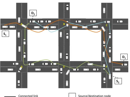
Figure 3.1 illustrates the local maximum problem. A, B, C, G, E, and F are junctions and data packets are to be sent from source node S to destination node D. Most existing schemes will forward data packets through the path A − B − C since road segments SA,B
and SB,C are highly connected. But once at intersection C, packets encounter the local
maximum problem since C and F are disconnected. This implies that packets will be either carried to junction F or forwarded back to intersection B in order to select another road segment, escalating therefore the end-to-end delay. With an up-to-date knowledge of network topology, packets would have been forwarded over the path A-G-E-F instead. Figure 3.2 shows a scenario where the path F-C-B-A is exploited by pairs (S1, D1)
and (S2, D2). This incurs large queuing delay at intermediate nodes, thus further
increas-ing the end-to-end delay. With the load balancincreas-ing capability, (S2, D2) packets can be
transmitted over the path F-E-G-A while (S1, D1) packets are forwarded over the path
S D A B C G E F Connected link Disconnected link A, B,C, .. : Intersection IDs Source/destination vehicle
Figure 3.1: Local maximum problem
A B C G E F S1 D1 S2 D2
Connected link Source/destination node
Given these shortcomings, we propose SCRP (see Chapter 4) that provides a solution to the aforementioned problems through:
1. Creating backbones over road segments and connecting them via bridge nodes at intersections. These nodes collect connectivity and delay information and assign weights to road segments. Packets are forwarded over road segments with low end-to-end delay, avoiding therefore the local maximum problem.
2. Identifying various routing paths between source and destination to be used for load balancing, reducing therefore data congestion.
3.2 DSRC Service Channel Selection
WAVE allows for data packets of infotainment applications to be transmitted within WAVE Basic Service Set (WBSS). It mandates that vehicles shall monitor received WSA messages to keep track of used SCHs in their 1-hop range. This way, they can select the least congested (i.e., used) SCH to establish their WBSS. Yet, this mechanism suffers from two major shortcomings: 1) vehicles might end-up using obsolete SCHs informa-tion due to WSA collisions; and 2) vehicles lack SCHs informainforma-tion within 2-hop range, yielding poor service quality as two providers within carrier sense range may select the same SCH to setup their WBSS. Several schemes have been proposed to help mitigating these issues. They are of two types: allocation-based and prediction-based.
3.2.1 Allocation-based Schemes
Allocation-based schemes require vehicles to maintain channel occupancy tables (OCTs), where the state of each SCH (i.e., free or busy) is stored. To disseminate SCH state information, OCTs are piggybacked into control messages (i.e., WSA [22, 23] or RTS/CTS [24, 25]) or data packets (i.e., [26, 27]).
Campolo et al [22] proposed CRaSCH, a cooperative reservation scheme for service channels. It requires providers to maintain SCH status vectors, containing information about SCHs status occupancy. Indeed, CRaSCH appends a new field to WSA, called ChannelGossip, indicating the current occupancy status of every SCH (i.e., 2-hop status
![Figure 2.2 [5] illustrates WAVE protocol stack. The physical and MAC layers are based on the IEEE 802.11p standard, which is a modified version of IEEE 802.11](https://thumb-eu.123doks.com/thumbv2/123doknet/7740665.251193/32.918.246.739.472.884/figure-illustrates-protocol-physical-layers-standard-modified-version.webp)