HAL Id: hal-01700646
https://hal.archives-ouvertes.fr/hal-01700646
Submitted on 12 Oct 2018
HAL is a multi-disciplinary open access
archive for the deposit and dissemination of
sci-entific research documents, whether they are
pub-lished or not. The documents may come from
teaching and research institutions in France or
abroad, or from public or private research centers.
L’archive ouverte pluridisciplinaire HAL, est
destinée au dépôt et à la diffusion de documents
scientifiques de niveau recherche, publiés ou non,
émanant des établissements d’enseignement et de
recherche français ou étrangers, des laboratoires
publics ou privés.
Regeneration study of Ni/hydroxyapatite spent catalyst
from dry reforming
Bruna Rêgo de Vasconcelos, Doan Pham Minh, Patrick Sharrock, Ange
Nzihou
To cite this version:
Bruna Rêgo de Vasconcelos, Doan Pham Minh, Patrick Sharrock, Ange Nzihou. Regeneration study
of Ni/hydroxyapatite spent catalyst from dry reforming. Catalysis Today, Elsevier, 2018, 310,
pp.107-115. �10.1016/j.cattod.2017.05.092�. �hal-01700646�
Regeneration study of Ni/hydroxyapatite spent catalyst from dry reforming
Bruna Rego de Vasconcelos
⁎, Doan Pham Minh, P. Sharrock, A. Nzihou
Université de Toulouse, Mines Albi, UMR CNRS 5302, Centre RAPSODEE, Campus Jarlard, F-81013 Albi cedex 09, FranceKeywords: hydroxyapatite dry reforming of methane nickel catalyst
syngas
catalyst regeneration
A B S T R A C T
In the present work, the regeneration of a spent nickel hydroxyapatite-based catalyst (Ni/Ca-HA1_S) used in dry reforming of methane (DRM) was investigated. Three successive cycles of DRM/regeneration were performed.
Two different gasifying agents were tested for the regeneration step: air and carbon dioxide (21%CO2/N2). The
aim was to evaluate the ability of regeneration of the catalyst under different atmospheres. The regeneration was performed in situ at 700 °C under 70 mL/min of gasifying agent. Reproducible results were obtained between each cycle for the two atmospheres tested and only a small irreversible deactivation was noticed. Several characterizations (SEM, TEM, TPR, XRD) of the fresh and spent catalysts allowed proving that the irreversible deactivation was provoked by densification of nickel particles and core-shell carbon formation. Despite the slight decrease in reactants’ conversions, selectivity to syngas was around 80–90% during the three cycles of DRM/ regeneration with both atmospheres and no changes in the selectivity were observed. The results proved that the Ni/Ca-HA1_S catalyst could be easily regenerated under different atmospheres and make it competitive for dry reforming of methane.
1. Introduction
Carbon dioxide (CO2) reforming of methane (CH4) (Eq.(1)) has gained increasing attention due to the conversion of two main green-house gases into syngas (mixture of hydrogen and carbon monoxide), which can further be used in the production of energy and of high-value added chemicals [1–3]. Nickel-based catalysts have been extensively investigated for this process due to its high catalytic activity in this reaction. However, they undergo severe deactivation due to catalyst sintering under the high temperatures required for the reaction and mostly due to coke deposition over the active sites of the catalyst[4,5]. In fact, many parallel reactions occur along with the dry reforming reaction (DRM) (Eq.(2)–(5)) and coke can originate from many of these reactions (Eq.(2)–(4)). + ⇄ + = ° : C CO kJ mol CO reformimg of methane H CO 2H 2 ∆H 247 / 2 4 2 2 298 (1) ⇄ + ° = − CO kJ mol Boudouard reaction 2 C CO ∆H2 298 172 / (2) ⇄ + ° = : C kJ mol Methane cracking H4 C 2H ∆H2 298 75 / (3) + ⇄ + ° = C O CO kJ mol Carbon gasification: ( )s H2 H ∆H2 298 131 / (4) + ⇄ + ° = C CO kJ mol
Reverse water-gas shift: O2 H2 H O ∆H2 298 41.2 / (5)
So, in the past few years, many studies have focused on the im-provement of the physico-chemical properties of the catalysts and on the optimization of the reaction conditions in order to obtain high catalytic conversion and stability during long periods of time[6]. They include the use of basic promoters, of supports with oxygen storage capacity, the combination of different transitions metals, the optimi-zation of preparation pathways of the catalysts etc[7–19]. Also, tem-perature, pressure, reactants ratio and type of reactor have been in-vestigated[10,20,21].
Nevertheless, the capacity of regeneration of the catalysts is also an important parameter. The regeneration process allows cleaning the coke deposit from the surface and the pores of the catalyst without destroying or modifying the structure of the catalyst[7]. This aspect has economic and environmental impact. In fact, the costs of regeneration should remain lower than the costs of obtaining fresh catalysts[7]. Moreover, regenerating the catalyst instead of disposing it as solid waste is an environmentally friendly option since the spent catalyst can form toxic metal compounds in the environment[22]. So, regeneration studies of spent catalysts have also been conducted aiming to re-use the deactivated catalysts.
Vicerich et al. [23]investigated the regeneration with oxygen di-luted in nitrogen at 450–550 °C of the PtReIn/Al2O3catalyst used in cyclohexane dehydrogenation and cyclopentane hydrogenolysis. They showed that the regeneration process could fully recover the activity of the spent catalyst. Wu et al.[15]showed that the regeneration at 300 °C
⁎Corresponding author. Bruna Rêgo de Vasconcelos, Ecole des Mines d’Albi-Carmaux, 81000 Albi France.
E-mail addresses:[email protected],[email protected](B. Rego de Vasconcelos).
of the Rh0.1Ni10/BN catalyst could remove the carbon deposit and re-activate the catalyst, but a small decrease in the activity was observed. Simson et al.[24]investigated the regeneration of a Pt/Rh catalyst after steam reforming of an ethanol/gasoline mixture. They showed that thermal treatment under air could fully restore the performance of the catalyst. However, after regeneration, their catalyst deactivated more quickly than the fresh one. Similarly, Sanchez et al.[25]reported that the catalytic performance of their reforming catalyst could be recovered by air combustion of the coke deposits but its selectivity to H2quickly decreased.
Most of the literature reports on catalyst regeneration are related to the combustion of coke with air due to its availability. Also, the me-chanism of carbon species oxidation by O2 has been widely in-vestigated. There are many references in the literature to carbon bulk diffusion through the metal particle, oxygen spillover and redox me-chanism[26]. However, coke deposits can be eliminated not only by O2 but also by different gasifying agents, such as steam and CO2 [27]. There are only few studies that investigated the effect of other gasifying agents such as CO2on the regeneration of catalysts[28]and the me-chanism of carbon removal by these gases is not yet well known[26]. Hydroxyapatite has been investigated as catalyst support in many different reactions such as water gas shift [29], partial oxidation of methane [30], steam reforming of glycerol [31]etc. In fact, hydro-xyapatite can undergo substitutions in its crystal lattice, which may favor the incorporation of an active phase to the catalyst[32,33]. Also, this material present high chemical and thermal stability, it has very low solubility in water and it does not sinter at temperatures lower than 700 °C [34,35]. Moreover, it presents basic sites that can reversibly adsorb carbon dioxide and help coke removal[36]. Despite all these advantages, only few works has been published using hydroxyapatite as catalyst for dry reforming of methane reaction. We have previously demonstrated that hydroxyapatite-based catalysts were performing for dry reforming of methane reaction[37,38]. So, in the present work, Ni/ hydroxyapatite catalyst was investigated in CO2reforming of CH4 re-action, with a focus on the regeneration process of the deactivated catalyst. The effect of gasifying agent on the re-use of the catalyst was also investigated by using two different gasifying agents: air and carbon dioxide. CO2was used in this work because it is one of the reactants of DRM and the reaction between CO2and solid carbon (Boudouard re-action, Eq.(2)) produces CO, which is one of the products of DRM. Also, the basic properties of the hydroxyapatite could favor the CO2 ad-sorption and consequently, solid carbon (C(s)) gasification. The objec-tive of this work was to evaluate the reproducibility of the performance of the Ni/hydroxyapatite catalyst under several reaction/regeneration cycles and under different regeneration atmospheres.
2. Materials and methods 2.1. Catalyst preparation
The hydroxyapatite (Ca10(PO4)6(OH)2) support used in this work was provided by PRAYON. Besides coke deposition, one of the reasons for catalyst deactivation is the support sintering[7]. So, as in this work the DRM reaction is performed at mild temperature (700 °C), the hy-droxyapatite support was previously sintered at 1000 °C for 5 h at 10 °C/min to ensure support stability during the catalytic tests and to avoid later catalyst deactivation by support sintering. The catalyst was prepared by incipient wetness impregnation method by impregnating the support with an aqueous solution of Ni(NO3)2·6H2O (Fisher Scien-tific, > 98 wt%). The amount of nickel on the catalyst was 5.7 wt.%. Then the catalyst was dried at 105 °C overnight. The catalyst was re-ferred to as Ni/Ca-HA1_S. In order to obtain more precise character-ization results of nickel particles on the catalyst during the reaction, a calcination step under air at 500 °C was performed for two hours before XRD, SEM and TEM analyses.
2.2. Dry reforming of methane
The dry reforming of methane was carried out in a fixed-bed tubular reactor with inner diameter of 8 mm 300 mg of the catalyst was diluted 2 times with inert alumina powder to improve heat exchange inside the catalyst bed. The same alumina was used to place the catalyst at the center of the reactor. The pressure drop in the reactor was 1.6 bar. The temperature of the reaction was controlled by a thermocouple placed at the center of the catalyst bed. The catalyst was reduced in situ at 700 °C for 2 h under 4%H2/N2flow (70 mL/min). Then, DRM was carried out for 30 h at 700 °C with a WHSV of 15882 mL h−1g
cat−1with a syn-thetic gas mixture containing 20% of CH4, 20% of CO2and 60% of N2 (volume percentage). A silica gel tube was used as water trap at the reactor outlet. Quantification of the water produced during the reaction was made by mass difference of this water trap. Also, a gas counter was used for the measurement of the total gas flow rate at the reactor outlet. The measure of the total gas flow rate at the reactor outlet allowed taking into account the change in the total number of moles between reactants and products to calculate the composition at the reactor outlet. Gas products were analyzed by aμ-GC A3000 (Agilent) equipped with a thermal conductivity detector (TCD).
Methane and carbon dioxide conversion and products selectivity were calculated as follows:
= − x CH conversion(%) (Q˙4 (CH ) Q˙(CH ) )/(Q ) 100 . (CH ) 4 in 4 out 4 in (6) = − CO conversion(%) (Q2 Q˙ )/(Q˙ )x100 .
(CO )2 in (CO )2 out (CO )2 in (7) =
H Oselectivity(%) (Q˙2 O(H2Oproduced))/(Q˙O(CO2consummed))x100 (8) =
COselectivity(%) (Q˙O(COproduced))/(Q˙O(CO2consummed))x100 (9) =
H selectivity(%) (Q˙2 H(H2produced))/(Q˙H(CH4consumed))x100 (10)
= +
C selectivity(%) (Q˙(s) Cs(out))/(Q˙C(CH4consumed) Q˙C(CO2consumed))x100 (11) whereQ˙(CH )4 inandQ˙(CH )4 out: methane molar flow rate (mmol h−1) at the reactor inlet and outlet;Q˙(CO )2 inandQ˙(CO )2 out: carbon dioxide flow rate (mmol h−1) at the reactor inlet and outlet; Q˙
O(H2Oproduced): atomic oxygen flow rate (mmol h−1) at the reactor outlet (under H
2O form); Q˙O(CO2consummed): atomic oxygen flow rate (mmol h−1) (under form of CO2consumed);Q˙O(COproduced): atomic oxygen flow rate (mmol h−1) at the reactor outlet (under CO form);Q˙H(H2produced): atomic hydrogen flow rate (mmol h−1) at the reactor outlet (under H
2form);Q˙H(CH4consumed): atomic hydrogen flow rate (mmol h−1) (under form of CH
4consumed); Q˙Cs(out): solid carbon flow rate at the outlet of the reactor deduced from mass balance.
The reaction/regeneration cycles were carried out as follows: a) Activation of the catalyst at 700 °C under 4%H2/N2 was per-formed for 2 h. The dry reforming reaction was carried out at 700 °C for 30 h as previously explained. After the reaction, the reactive gases were switched with air. The temperature was kept at 700 °C and 70 mL/min of air flowed through the catalyst for 1h30 min. During the regenera-tion process, the concentraregenera-tion of CO2resulting from the oxidation of coke was monitored by a gas chromatography.
b) Activation of the catalyst at 700 °C under 4%H2/N2 was per-formed for 2 h. The dry reforming reaction was carried out at 700 °C for 30 h as previously explained. After the reaction, the reactive gases were switched to a gas mixture containing 21% of CO2and 79% of N2 (vo-lume percentage). The temperature was kept at 700 °C and 70 mL/min of the gas mixture flowed through the catalyst for 1h30 min. During the regeneration process, the concentration of CO resulting from the oxi-dation of coke was monitored by gas chromatography.
Three cycles of DRM/regeneration for both gasifying agents were performed to test the regeneration capacity of the hydroxyapatite cat-alyst under different atmospheres.
2.3. Characterization
N2adsorption isotherms were recorded with a Micromeritics Tristar II 3020 to evaluate the specific surface area and the pore volume of the support and of the fresh catalyst. BET surface area was calculated from the nitrogen adsorption isotherms. Prior to the analyses, the samples were outgassed at 105 °C for 24 h at low pressure (< 100 mbar).
Carbon dioxide temperature-programmed desorption (CO2-TPD) was performed on a Micromeritics AutoChem 2920 Analyzer equipped with a thermal conductivity detector (TCD) to evaluate the basicity of the hydroxyapatite support. 100 mg of the support was pretreated at 800 °C (10 °C/min) under helium flow and then it was cooled to 50 °C at 10 °C/min. Then, the sample was saturated with 0.5%CO2/N2(15 mL/ min) for 30 min. Afterwards, 25 mL/min of He were flushed for 30 min to eliminate physisorbed CO2molecules. TPD was finally recorded from 50 to 800 °C at a heating rate of 10 °C/min.
X-ray diffraction (XRD) was carried out using a Phillips Panalytical X’Pert MPD diffractometer operating with Cu Kα radiation (λ = 1.543 Å) over a 2θ range of 10−75° and scan step size of 0.042°s−1. Prior to the analyses, the catalyst was calcined at 500 °C under air.
Inductively coupled plasma-optical emission spectroscopy (ICP-OES) analyses were performed with a HORIBA Jobin Yvon Ultima 2 apparatus to evaluate the Ni content in the catalyst sample. Prior to the measurements, 100 mg of the hydroxyapatite-based catalysts were dissolved in aqua regia (33vol% HNO3+ 67vol% HCl) and heated at 90 °C for 1 h.
Environmental Scanning Electron Microscopy (ESEM) analysis was performed of a Philips XL30 ESEM FEG to characterize the shape and size of support and metal particles.
Transmission electron microscopy (TEM) images of fresh and spent catalyst were recorded on a MET JEOL ARM200F. Prior to the analyses, the catalysts were calcined at 500 °C under air atmosphere.
Temperature-programmed reduction (TPR) profiles of the dried catalysts were recorded with a Micromeritics AutoChem 2920 Analyzer in the temperature range of 25–850 °C. 100 mg of the sample was placed in a quartz reactor and reduced by a 5%H2/N2gas mixture with a heating rate of 10 °C/min. Prior to the analysis, the sample was purged under pure helium at 100 °C for 30 min to clean the surface of the sample.
3. Results and discussion 3.1. Characterization of samples
3.1.1. Physico-chemical properties of support and catalyst
Table 1depicts the specific surface area (SBET), pore volume (Vp) and nickel amount of the Ca-HA1_S support and of the Ni/Ca-HA1_S catalyst. For the purpose of comparison, the SBETand the Vpof the hydroxyapatite support before thermal treatment (Ca-HA1) is also shown. The initial hydroxyapatite presented 7 m2/g of specific surface area and negligible pore volume. As expected, the hydroxyapatite support (Ca-HA1_S) and the Ni/Ca-HA1_S catalyst presented very low specific surface area and pore volume. In fact, sintering took place during thermal treatment at high temperature, which resulted in the loss of surface area and porosity. The addition of nickel to the support
did not modify its specific surface area. The nickel loss was related to the fixation of the metal on the flask wall during the impregnation step. 3.1.2. CO2-Temperature programmed desorption (CO2-TPD)
CO2-TPD was conducted to evaluate the density and the strength of basic sites of the Ca-HA1_S support in order to evaluate the influence of the hydroxyapatite support on the performance of the catalyst. The density of basic sites is represented by the area under the curves and the strength of the sites is represented by the temperature of desorption. High temperatures represent strong basic sites. For comparison, the hydroxyapatite before thermal treatment (Ca-HA1) was also evaluated.
Fig. 1presents the CO2-TPD curves of this support.
The hydroxyapatite before thermal treatment (Ca-HA1) presented a small peak centered at about 150 °C and a broad peak between 200 and 600 °C. The desorption peaks of this material covered a wide range of temperature, which indicated the presence of weak, medium and strong basic sites. The thermal treatment completely changed the basicity of the initial hydroxyapatite. No desorption peaks were observed for the Ca-HA1_S support, which indicated that the basicity of this support was negligible after thermal treatment. In fact, the thermal treatment led to a full densification of the hydroxyapatite and destroyed its surface functions.
3.1.3. XRD analysis
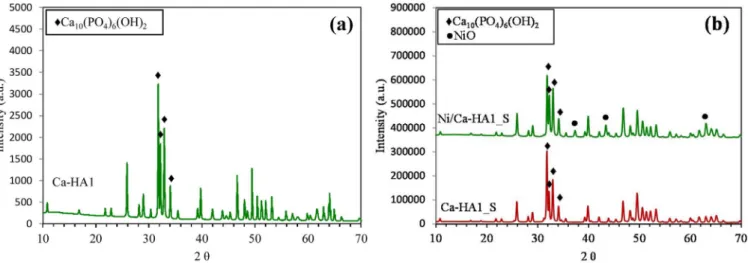
XRD patterns of support and catalyst is shown inFig. 2.
Both support and catalyst showed the presence of the hydro-xyapatite phase (Ca10(PO4)6(OH)2) with the main peaks at 31.9°, 32.3°, 33.0° and 34° (pattern number: COD 96-230-0274). Comparison be-tween XRD patterns of the support before (Fig. 2a) and after (Fig. 2b) thermal treatment indicated that the thermal treatment of the hydro-xyapatite did not change its structure, only its crystallinity. Besides the hydroxyapatite phase, the Ni/Ca-HA1_S catalyst also presented a NiO phase with main diffraction peaks at 37°, 43° and 63°. No peaks of Ni-exchanged hydroxyapatite were detected, which suggested the nickel was mainly located on the surface of the hydroxyapatite and not in its structure.
3.1.4. SEM and TEM analyses
Fig. 3shows the SEM images of the Ca-HA1_S support and of the Ni/ Ca-HA1_S fresh catalyst.
Fig. 3a shows the SEM image of the hydroxyapatite support after the thermal treatment. A coalescence of the hydroxyapatite particles could be observed, indicating the sintering of this material.Fig. 3b shows the SEM image of the Ni/Ca-HA1_S catalyst. Large nickel particles of about 100–200 nm could be observed. However, SEM analysis is not precise enough to indicate if each particle observed is only one nickel particle
Table 1
Physico-chemical properties of support and catalyst.
Sample Textural characterization ICP-OES
SBET(m2/g) Vp(cm3/g) Ni wt.%
Ca-HA1 7 nd –
Ca-HA1_S < 3 ≈0 –
Ni/Ca-HA1_S < 3 ≈0 4
Fig. 1. CO2-TPD of hydroxyapatite support before (e Ca-HA1) and after thermal
or an agglomerate.
To confirm the SEM results, TEM analysis was performed.Fig. 4
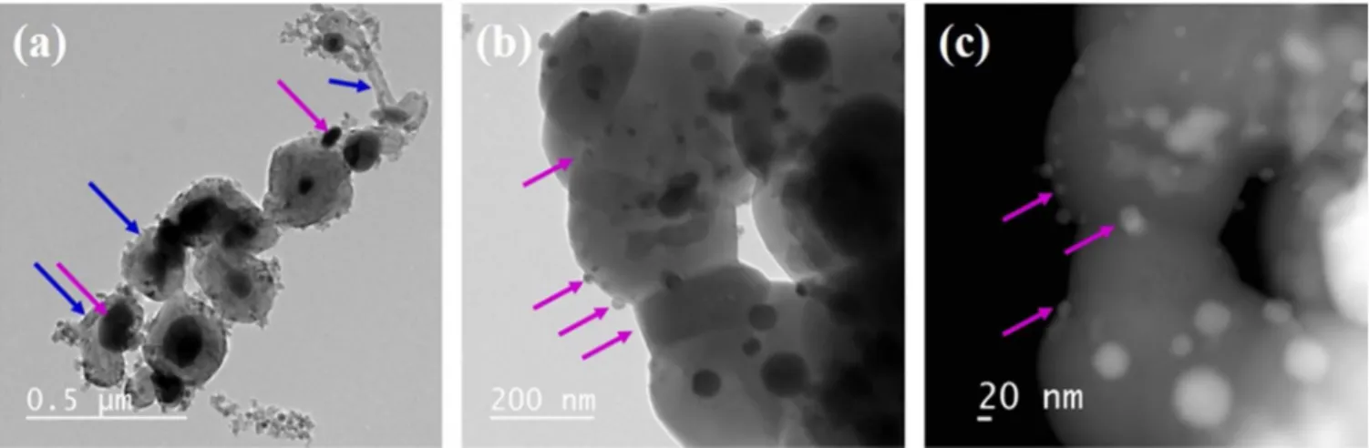
illustrates the TEM images of the fresh Ni/Ca-HA1_S catalyst. TEM analysis showed the presence of large nickel particles with sizes between 100 and 200 nm. Also, the nickel particles observed are porous and have square shape (2D), which corresponded to the cubic structure of NiO[2,19,39].
3.1.5. TPR analysis
TPR analysis was performed to evaluate the reducibility of the Ni/ Ca-HA1_S catalyst.Fig. 5shows the TPR curve of this catalyst.
Ni/Ca-HA1_S catalyst presented two reduction peaks centered at 395 and 402 °C. According to Ahmed et al. [40]and Wu et al.[41], these peaks correspond to the reduction of NiO species with different oxidation degrees located at the external surface of the support and weakly interacting with the support. This result confirms the XRD analysis.
3.2. Catalyst behavior under DRM/regeneration cycles
3.2.1. Catalytic performance under DRM/Air-regeneration cycles
Fig. 6shows the evolution with time on stream (TOS) of the CH4and CO2conversions as well as of the H2, CO, H2O and solid carbon (C(s)) selectivities for the Ni/Ca-HA1_S catalyst under three successive cycles of DRM/Air regeneration.
In the first cycle (blue dots), the Ni/Ca-HA1_S catalyst showed high CH4and CO2conversion around 70% that decreased to 52% and 61%,
respectively during 30 h oh TOS. H2and CO selectivity were constant at around 90%. As consequence, low H2O and C(s) were obtained. H2O selectivity was constant at around 10% and C(s)was lower than 10%. The deactivation of the catalyst was probably related to coke deposition (Eq. 2-4) and/or catalyst sintering. The catalyst presented initially good activity and stability on DRM for 30 h of TOS, showing that the hy-droxyapatite-based catalyst was performing for this reaction. This proves that the physical properties (low SBET and Vp, Table 1) are compensated by its chemistry.
After in situ regeneration by coke combustion under air flow and reactivation under 4%H2/N2 flow, the catalyst exhibited similar per-formance as in the first cycle, showing only a small decrease in CH4and CO2conversions (red dots). This suggested that irreversible deactiva-tion caused by catalyst sintering took place. CH4and CO2conversions were initially around 60 and 70% and decreased to 47 and 56%, re-spectively during 30 h of TOS. However, H2and CO selectivities were constant at about 90% during the test, as in the first cycle. H2O and C(s) selectivities were also similar at around 10%.
Subsequent to another step of in situ regeneration and reactivation, the catalyst exhibited similar performance as in the second cycle, but also with slight decrease in CH4and CO2conversions. The slight de-activation in this cycle can also be explained by catalyst sintering. CH4 and CO2conversions were initially at 55 at 61% and decreased to 44 and 54% during the test. H2and CO selectivity were constant at 80%. Also, H2O and C(s)were kept around 10% during 30 h of test.
TEM images of the spent catalyst after the three cycles of DRM/ regeneration confirms the catalyst deactivation by sintering. Fig. 7
Fig. 2. XRD patterns of (a) Ca-HA1 support before thermal treatment and of (b) Ca-HA1_S support (after thermal treatment) and of Ni/Ca-HA1_S catalyst.
presents the TEM images of the spent catalyst after three cycles of DRM/Air regeneration.
Fig. 7a shows the formation of carbon deposit in the form of carbon nanofibers (CNFs) and core-shell. The formation of carbon was possible due to the relatively low metal-support interaction (Fig. 5) and to the presence of large nickel particles (Fig. 4). The CNFs play minor role on the catalyst deactivation because they mostly grow away from the catalyst surface and do not cover the active sites[42–44]. Also, they can push nickel particles from the supports and in some cases, they do not encapsulate them. In many cases, the nickel particles are on the tip of the CNFs and thus still available to the reaction [42,44–46]. On the other hand, the core-shell structure covers completely the active site of the catalyst and is hardly removed, leading to catalyst deactivation
[43,47]. So, the small decrease in the performance of the catalyst be-tween each cycle could be partially related to the formation of core-shell carbon.
Fig. 7b and c illustrates nickel particles over the spent catalyst after three cycles of DRM/Air regeneration. The nickel particles on the spent catalyst have a completely different shape and structure than the nickel particles on the fresh catalyst (Fig. 4). They have round shape, size about 10–50 nm and are not porous. The nickel particles suffered densification during the reaction, losing their surface and porosity,
which could also explain the small irreversible catalyst deactivation between cycles. However, it is worth noting that these nickel particles of round shape and small sizes (10–50 nm) are not poisoned by coke. In fact, it is widely accepted that the formation of coke on small nickel particles is not energetically favored[8]. Moreover, it is the metallic step edges that act as growth sites for the carbon growth[48,49]. So, despite the small loss of activity due the densification of the nickel particles, it might have prevented the deposition of coke over these particles and thus stabilizing the catalyst. This also suggests that coke deposition occurred mainly in the first hours of the reaction while the nickel particles still had large size (100–200 nm) and square shape. 3.2.2. Catalytic performance under DRM/CO2-regeneration cycles
Fig. 8shows the evolution with time on stream (TOS) of the CH4and CO2conversions as well as of the H2, CO, H2O and C(s)selectivities for the Ni/Ca-HA1_S catalyst under three successive cycles of DRM/CO2 regeneration. The results obtained with DRM/CO2regeneration cycles are very similar to those obtained with the DRM/Air regeneration cy-cles.
In the first cycle (blue dots), the Ni/Ca-HA1_S catalyst showed in-itial CH4and CO2conversion around 70 and 76%, respectively and then decreased to 46% and 57%, respectively during 30 h of TOS. As for the previous results, this deactivation could be related to carbon deposition and/or catalyst sintering. H2 and CO selectivity were kept constant around 90% during the test. Also, H2O and C(s)were stable around 10% during the test.
Subsequent to an in situ regeneration under 21%CO2/N2flow and reactivation under 4%H2/N2, a small decrease in the CH4and CO2was observed compared to the first cycle, indicating the presence of irre-versible catalytic deactivation. Although, high syngas yield was ob-tained. H2and CO selectivities were stable and around 90% during the test. H2O and C(s)were also stable around 10% during the test.
The third cycle of DRM/CO2regeneration (green dots) showed si-milar results to the second cycle (red dots), but a small decrease in the initial CH4and CO2conversions was also observed. The slight deacti-vation in this cycle could also be explained by catalyst sintering. CH4 and CO2conversions decreased from around 50 and 60% to 41 and 52%. However, as for the previous cycles, high H2and CO selectivities were obtained. H2and CO selectivities were constant at around 80% during 30 h of test. Consequently, low selectivity to byproducts was obtained. H2O and C(s)were constant at 10% during the test.
Fig. 4. TEM of Ni/Ca-HA1_S fresh catalyst; → Ni particle, → hydroxyapatite.
-0.95 -0.9 -0.85 -0.8 -0.75 0 100 200 300 400 500 600 700 800 la ngi S D C T Temperature (°C) Ni/Ca-HA1_S
0 10 20 30 40 50 60 70 80 90 100 0 5 10 15 20 25 30 CH 4 Conversion(%) Time on stream (h)
1st cycle 2nd cycle 3rd cycle
(a)
0 10 20 30 40 50 60 70 80 90 100 0 5 10 15 20 25 30 CO 2 Conversion(%) Time on stream (h)1st cycle 2nd cycle 3rd cycle
(b)
0 10 20 30 40 50 60 70 80 90 100 0 5 10 15 20 25 30 H2 (%) Selectivity Time on stream (h) 1st cycle 2nd cycle 3rd cycle(c)
0 10 20 30 40 50 60 70 80 90 100 0 5 10 15 20 25 30 Selectivity(%) CO Time on stream (h) 1st cycle 2nd cycle 3rd cycle(d)
0 10 20 30 40 50 60 70 80 90 100 0 5 10 15 20 25 30 H2 Selectivity(%) O Time on stream (h)1st cycle 2nd cycle 3rd cycle
(e)
0 10 20 30 40 50 60 70 80 90 100 0 5 10 15 20 25 30 C(s ) Selectivity(%) Time on stream (h) 1st cycle 2nd cycle 3rd cycle(f)
Fig. 6. Catalytic performance of Ni/Ca-HA1_S catalyst under 3 cycles of DRM/Air-regeneration. Reaction conditions: T=700 °C, WHSV = 15882 mL h−1g
cat−1, CH4/CO2= 1,
TOS=30 h. Regeneration conditions: 1h30 at 700 °C with air flow.
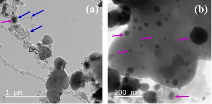
Fig. 9 presents the TEM images of the spent catalyst after three cycles of DRM/CO2regeneration.
Fig. 9a shows the presence of carbon deposit under CNFs and core-shell forms. These were already observed for the Ni/Ca-HA1_S catalyst after 3 cycles of DRM/Air regeneration. The irreversible deactivation of this catalyst between the cycles was related to the formation of the core-shell carbon, which is hardly removed. Moreover, this catalyst also presented non-porous nickel particles with round shape and with size around 10–50 nm (Fig. 9b), indicating the occurrence of densification during the reaction. As previously explained, the densification of nickel particles provoked irreversible deactivation, which led to a small de-crease in the performance of the catalyst. However, it also improved the stability of the catalyst since the formation of small nickel particles prevented the growth of coke.
Fig. 10presents a summary of the results, comparing the values of CH4conversion and H2selectivity between regeneration under air and under CO2. The “fresh” and “spent” values correspond to the perfor-mance of the catalyst at the beginning and at the end of the first cycle, respectively. The values of “Regenerated (2nd cycle)” and “Regenerated (3rd cycle)” correspond to the values of performance at the begging of
2nd and 3rd cycles after the regeneration step, respectively.
The results obtained with air regeneration are quite similar than those obtained with CO2/N2regeneration. The catalyst after regenera-tion steps with both atmospheres always showed higher CH4conversion than the spent catalyst (red column). This indicates that both atmo-spheres used could successfully regenerate the catalyst surface by eliminating the carbon deposit.
As previously presented, the values of CH4conversion after the re-generation steps are slightly lower than the CH4conversion values of the fresh catalyst (dark blue column) due to irreversible deactivation provoked by core-shell carbon formation and nickel particles densifi-cation. Nevertheless, the values of H2 selectivity after regeneration steps under air and CO2were relatively stable and comparable to the H2 selectivity of the fresh catalyst. This suggests that the occurrence of irreversible deactivation did not affect the selectivity of the catalyst to syngas.
These results showed that the Ni/Ca-HA1_S catalyst can be easily regenerated under different atmospheres. An optimization of the re-generation step including changing the temperature and the duration of the regeneration are still needed to remove the core-shell carbon of the
0 10 20 30 40 50 60 70 80 90 100 0 5 10 15 20 25 30 CH 4 )% ( noi sr ev no C Time on stream (h)
1st cycle 2nd cycle 3rd cycle
(a)
0 10 20 30 40 50 60 70 80 90 100 0 5 10 15 20 25 30 CO 2 )% ( noi sr ev no C Time on stream (h)1st cycle 2nd cycle 3rd cycle
(b)
0 10 20 30 40 50 60 70 80 90 100 0 5 10 15 20 25 30 H2 )% ( yti vit cel eS Time on stream (h) 1st cycle 2nd cycle 3rd cycle(c)
0 10 20 30 40 50 60 70 80 90 100 0 5 10 15 20 25 30 )% (y ti vit cel eS O C Time on stream (h) 1st cycle 2nd cycle 3rd cycle(d)
0 10 20 30 40 50 60 70 80 90 100 0 5 10 15 20 25 30 H2 )% ( yti vit cel eS O Time on stream (h) 1st cycle 2nd cycle 3rd cycle(e)
0 10 20 30 40 50 60 70 80 90 100 0 5 10 15 20 25 30 C(s) )% ( yti vit cel eS Time on stream (h) 1st cycle 2nd cycle 3rd cycle(f)
Fig. 8. Catalytic performance of Ni/Ca-HA1_S catalyst under 3 cycles of DRM/CO2-regeneration. Reaction conditions: T=700 °C, WHSV = 15882 mL h−1gcat−1, CH4/CO2= 1,
catalyst surface and obtain higher reactants’ conversion. 4. Conclusions
The regeneration of a hydroxyapatite-based catalyst (Ni/Ca-HA1_S) was investigated during three successive cycles of DRM/regeneration. The in situ regeneration was carried out at 700 °C for 1h30 after a cycle of DRM at 700 °C for 30 h. The capacity of regeneration of the catalyst was tested under two different atmospheres: air and 21%CO2/N2. The catalyst presented good reproducibility between cycles for both atmo-spheres tested and only a small deactivation between cycles was
observed. The irreversible deactivation between cycles was provoked by the formation of core-shell carbon and by densification of the nickel particles during the reaction. However, after densification the nickel particles had round shape and small size (10–50 nm), which helped to prevent further carbon deposition. Despite the small loss in the re-actants’ conversion, the syngas selectivity was constant between cycles, which indicated that the deactivation of the catalyst did not affect its selectivity. These results showed the Ni/Ca-HA1_S catalyst could be easily in situ regenerated under different atmospheres and make it competitive for dry reforming of methane. Further tests are needed to optimize the regeneration step and eliminate the core-shell carbon deposits.
Acknowledgments
The authors gratefully acknowledge PRAYON for their financial support to this study. The technical help of colleagues at RAPSODEE research center is also acknowledged.
References
[1] Y. Kathiraser, U. Oemar, E.T. Saw, Z. Li, S. Kawi, Kinetic and mechanistic aspects for CO2reforming of methane over Ni based catalysts, Chem. Eng. J. (2015),http://
dx.doi.org/10.1016/j.cej.2014.11.143.
[2] G. Moradi, F. Khezeli, H. Hemmati, Syngas production with dry reforming of me-thane over Ni/ZSM-5 catalysts, J. Nat. Gas Sci. Eng. 33 (2016) 657–665,http://dx. doi.org/10.1016/j.jngse.2016.06.004.
[3] M. Farniaei, M. Abbasi, H. Rahnama, M.R. Rahimpour, A. Shariati, Syngas pro-duction in a novel methane dry reformer by utilizing of tri-reforming process for energy supplying: modeling and simulation, J. Nat. Gas Sci. Eng. 20 (2014) 132–146,http://dx.doi.org/10.1016/j.jngse.2014.06.010.
[4] X. Lin, R. Li, M. Lu, C. Chen, D. Li, Y. Zhan, L. Jiang, Carbon dioxide reforming of methane over Ni catalysts prepared from Ni-Mg-Al layered double hydroxides: in-fluence of Ni loadings, Fuel 162 (2015) 271–280,http://dx.doi.org/10.1016/j.fuel. 2015.09.021.
[5] M.S. Aw, M. Zorko, P. Djinović, A. Pintar, Insights into durable NiCo catalysts on (-SiC/CeZrO2and (-Al2O3/CeZrO2advanced supports prepared from facile methods
for CH4-CO2dry reforming, Appl. Catal. B Environ. 164 (2015) 100–112,http://dx.
doi.org/10.1016/j.apcatb.2014.09.012.
[6] Z. Abdelsadek, M. Sehailia, D. Halliche, V.M. Gonzalez-Delacruz, J.P. Holgado, K. Bachari, A. Caballero, O. Cherifi, In-situ hydrogasification/regeneration of NiAl-hydrotalcite derived catalyst in the reaction of CO2 reforming of methane: a ver-satile approach to catalyst recycling, J. CO2Util. 14 (2016) 98–105,http://dx.doi.
org/10.1016/j.jcou.2016.03.004.
[7] O. Muraza, A. Galadima, A review on coke management during dry reforming of methane, Int. J. Energy Res. 39 (2016) 1196–1216,http://dx.doi.org/10.1002/ er3295.
Fig. 9. TEM of Ni/Ca-HA1_S spent catalyst after three cycles of DRM/CO2regeneration; → Ni particle, → carbon.
0 10 20 30 40 50 60 70 80 90 100 CH 4 )% ( noi sr ev no C Fresh Spent
Regenerated Air (2nd cycle) Regenerated CO2 (2nd cycle) Regenerated Air (3rd cycle) Regenerated CO2 (3rd cycle)
(a)
0 10 20 30 40 50 60 70 80 90 100 H2 )% ( yti vit cel eS Fresh SpentRegenerated Air (2nd cycle) Regenerated CO2 (2nd cycle) Regenerated Air (3rd cycle) Regenerated CO2 (3rd cycle)
(b)
Fig. 10. Comparison between Air and CO2regeneration: (a) CH4conversion, (b) H2
[8] J. Zhang, F. Li, Coke-resistant Ni@SiO2catalyst for dry reforming of methane, Appl.
Catal. B Environ. 176-177 (2015) 513–521,http://dx.doi.org/10.1016/j.apcatb. 2015.04.039.
[9] F. Wang, L. Xu, J. Zhang, Y. Zhao, H. Li, H.X. Li, K. Wu, G.Q. Xu, W. Chen, Tuning the metal-support interaction in catalysts for highly efficient methane dry reforming reaction, Appl. Catal. B Environ. 180 (2016) 511–520,http://dx.doi.org/10.1016/j. apcatb.2015.07.001.
[10] C.J. Liu, J. Ye, J. Jiang, Y. Pan, Progresses in the preparation of coke resistant Ni-based catalyst for steam and CO 2 reforming of methane, ChemCatChem 3 (2011) 529–541,http://dx.doi.org/10.1002/cctc.201000358.
[11] L. Coronel, J.F. Múnera, E.A. Lombardo, L.M. Cornaglia, Pd based membrane re-actor for ultra pure hydrogen production through the dry reforming of methane, Experimental and modeling studies, Appl. Catal. A Gen. 400 (2011) 185–194, http://dx.doi.org/10.1016/j.apcata.2011.04.030.
[12] A. Ballarini, F. Basile, P. Benito, I. Bersani, G. Fornasari, S. De Miguel, S.C.P. Maina, J. Vilella, A. Vaccari, O.A. Scelza, Platinum supported on alkaline and alkaline earth metal-doped alumina as catalysts for dry reforming and partial oxidation of me-thane, Appl. Catal. A Gen. 433-434 (2012) 1–11,http://dx.doi.org/10.1016/j. apcata.2012.04.037.
[13] J. Xu, W. Zhou, Z. Li, J. Wang, J. Ma, Biogas reforming for hydrogen production over nickel and cobalt bimetallic catalysts, Int. J. Hydrogen Energy. 34 (2009) 6646–6654,http://dx.doi.org/10.1016/j.ijhydene.2009.06.038.
[14] Z. Hou, P. Chen, H. Fang, X. Zheng, T. Yashima, Production of synthesis gas via methane reforming with CO2on noble metals and small amount of noble-(Rh-)
promoted Ni catalysts, Int. J. Hydrogen Energy. 31 (2006) 555–561,http://dx.doi. org/10.1016/j.ijhydene.2005.06.010.
[15] J.C.S. Wu, H.C. Chou, Bimetallic Rh-Ni/BN catalyst for methane reforming with CO2, Chem. Eng. J. 148 (2009) 539–545,http://dx.doi.org/10.1016/j.cej.2009.01.
011.
[16] M. García-Diéguez, E. Finocchio, M.Á. Larrubia, L.J. Alemany, G. Busca, Characterization of alumina-supported Pt, Ni and PtNi alloy catalysts for the dry reforming of methane, J. Catal. 274 (2010) 11–20,http://dx.doi.org/10.1016/j. jcat.2010.05.020.
[17] J. Estephane, S. Aouad, S. Hany, B. El Khoury, C. Gennequin, H. El Zakhem, J. El Nakat, A. Aboukaïs, E. Abi Aad, CO2 reforming of methane over Ni–Co/ZSM5 catalysts, Aging and carbon deposition study, Int. J. Hydrogen Energy. 40 (2015) 9201–9208,http://dx.doi.org/10.1016/j.ijhydene.2015.05.147.
[18] K. Klaigaew, C. Samart, C. Chaiya, Y. Yoneyama, N. Tsubaki, P. Reubroycharoen, Effect of preparation methods on activation of cobalt catalyst supported on silica fiber for Fischer-Tropsch synthesis, Chem. Eng. J. 278 (2015) 166–173,http://dx. doi.org/10.1016/j.cej.2014.11.025.
[19] M.E. Gálvez, A. Albarazi, P. Da Costa, Enhanced catalytic stability through non-conventional synthesis of Ni/SBA-15 for methane dry reforming at low tempera-tures, Appl. Catal. A Gen. 504 (2015) 143–150,http://dx.doi.org/10.1016/j.apcata. 2014.10.026.
[20] M. Usman, W.M.A. Wan Daud, H.F. Abbas, Dry reforming of methane: Influence of process parameters—A review, Renew. Sustain. Energy Rev. 45 (2015) 710–744, http://dx.doi.org/10.1016/j.rser.2015.02.026.
[21] J.-M. Lavoie, Review on dry reforming of methane, a potentially more en-vironmentally-friendly approach to the increasing natural gas exploitation, Front. Chem. 2 (2014) 1–17,http://dx.doi.org/10.3389/fchem.2014.00081.
[22] A. Haghlesan, R. Alizadeh, Reactivation of an industrial spent catalyst as an en-vironmental waste by ultrasound assisted technique for using in styrene production, Chem. Eng. Process. Process Intensif. 110 (2016) 64–72,http://dx.doi.org/10. 1016/j.cep.2016.09.015.
[23] M.A. Vicerich, M. Oportus, V.M. Benitez, P. Reyes, C.L. Pieck, Influence of time and temperature on the regeneration of PtReIn/Al2O3naphtha reforming catalysts,
Catal. Letters. 144 (2014) 1178–1187, http://dx.doi.org/10.1007/s10562-014-1282-9.
[24] A. Simson, R. Farrauto, M. Castaldi, Steam reforming of methanol/gasoline mix-tures: deactivation, regeneration and stable performance, Appl. Catal. B Environ. 106 (2011) 295–303.
[25] E. Sanchez, R. Comelli, Hydrogen by glycerol steam reforming on a nickel-alumina catalyst: deactivation process and regeneration, Int. J. Hydrogen Energy. 37 (2012) 14740–14746.
[26] S.A. Theofanidis, R. Batchu, V.V. Galvita, H. Poelman, G.B. Marin, Carbon gasifi-cation from Fe-Ni catalysts after methane dry reforming, Appl. Catal. B Environ. 185 (2016) 42–55,http://dx.doi.org/10.1016/j.apcatb.2015.12.006.
[27] J.R. Rostrup-Nielsen, Catalytic steam reforming, Catal. Sci. Technol. 5 (1984) 1–117,http://dx.doi.org/10.1007/978-3-642-93247-2_1.
[28] L. Bednarczuk, P. Ramírez de la Piscina, N. Homs, H2-production from CO2-assisted
ethanol steam reforming: the regeneration of Ni-based catalysts, Int. J. Hydrogen Energy. 0 (2014) 2–9,http://dx.doi.org/10.1016/j.ijhydene.2015.01.061. [29] A. Venugopal, M.S. Scurrell, Hydroxyapatite as a novel support for gold and
ru-thenium catalysts Behaviour in the water gas shift reaction, Appl. Catal. A Gen. 245 (2003) 137–147,http://dx.doi.org/10.1016/S0926-860X(02)00647-6.
[30] J.H. Jun, T.J. Lee, T.H. Lim, S.W. Nam, S.A. Hong, K.J. Yoon, Nickel-calcium phosphate/hydroxyapatite catalysts for partial oxidation of methane to syngas: characterization and activation, J. Catal. 221 (2004) 178–190,http://dx.doi.org/ 10.1016/j.jcat.2003.07.004.
[31] Z. Yaakob, L. Hakim, M. Kumar, M. Ismail, W. Daud, Hydroxyapatite supported Nickel catalyst for hydrogen production, Am. J. Sci. Ind. Res. 1 (2010) 122–126, http://dx.doi.org/10.5251/ajsir.2010.1.2.122.126.
[32]D.E.P.T.S.B. Narasaraju, Review Some physico-chemical aspects of hydroxylapatite, J. Mater. Sci. 31 (1996) 1–21.
[33] E. Boanini, M. Gazzano, A. Bigi, Ionic substitutions in calcium phosphates synthe-sized at low temperature, Acta Biomater. 6 (2010) 1882–1894,http://dx.doi.org/ 10.1016/j.actbio.2009.12.041.
[34]A. Ababou, Etude expérimentale et théorique du préfrittage et du frittage de l’hy-droxyapatite, Université de Limoges (1994).
[35]D. Bernache-assollant, A. Ababou, E. Champion, M. Heughebaert, Sintering of cal-cium phosphate hydroxyapatite Ca10(PO4)6(OH)2 I. Calcination and particle growth, J. Eur. Ceram. Soc. 23 (2003) 229–241.
[36] Z. Boukha, M. Kacimi, M.F.R. Pereira, J.L. Faria, J.L. Figueiredo, M. Ziyad, Methane dry reforming on Ni loaded hydroxyapatite and fluoroapatite, Appl. Catal. A Gen. 317 (2007) 299–309,http://dx.doi.org/10.1016/j.apcata.2006.10.029. [37] B. Rêgo de Vasconcelos, L. Zhao, P. Sharrock, A. Nzihou, D. Pham Minh, Catalytic
transformation of carbon dioxide and methane into syngas over ruthenium and platinum supported hydroxyapatites, Appl. Surf. Sci. 390 (2016) 141–156,http:// dx.doi.org/10.1016/j.apsusc.2016.08.077.
[38]B. Rêgo De Vasconcelos, Phosphates-based catalysts for synthetic gas (syngas) production using CO2and CH4, Ecole des Mines d’Albi-Carmaux (2016). [39] C. Courson, L. Udron, C. Petit, a Kiennemann, Grafted NiO on natural olivine for dry
reforming of methane, Sci. Technol. Adv. Mater. 3 (2002) 271,http://dx.doi.org/ 10.1016/S1468-6996(02)00026-8.
[40] W. Ahmed, M.R.N. El-Din, A.A. Aboul-Enein, A.E. Awadallah, Effect of textural properties of alumina support on the catalytic performance of Ni/Al2O3catalysts for
hydrogen production via methane decomposition, J. Nat. Gas Sci. Eng. 25 (2015) 359–366,http://dx.doi.org/10.1016/j.jngse.2015.05.015.
[41] P. Wu, X. Li, S. Ji, B. Lang, F. Habimana, C. Li, Steam reforming of methane to hydrogen over Ni-based metal monolith catalysts, Catal. Today. 146 (2009) 82–86, http://dx.doi.org/10.1016/j.cattod.2009.01.031.
[42] H. Ay, D. Üner, Dry reforming of methane over CeO2supported Ni, Co and Ni-Co
catalysts, Appl. Catal. B Environ. 179 (2015) 128–138,http://dx.doi.org/10.1016/ j.apcatb.2015.05.013.
[43] C. Wang, N. Sun, N. Zhao, W. Wei, J. Zhang, T. Zhao, Y. Sun, C. Sun, H. Liu, C.E. Snape, The properties of individual carbon residuals and their influence on the deactivation of Ni-CaO-ZrO2catalysts in CH4dry reforming, ChemCatChem 6
(2014) 640–648,http://dx.doi.org/10.1002/cctc.201300754.
[44] B. Rêgo de Vasconcelos, N.D. Tran, D. Pham Minh, A. Nzihou, P. Sharrock, Synthesis of carbon nanotubes/hydroxyapatite composites using catalytic methane cracking, Compos. Interfaces. 22 (2015) 673–687,http://dx.doi.org/10.1080/ 09276440.2015.1060055.
[45] A.M. Amin, E. Croiset, W. Epling, Review of methane catalytic cracking for hy-drogen production, Int. J. Hyhy-drogen Energy. 36 (2011) 2904–2935,http://dx.doi. org/10.1016/j.ijhydene.2010.11.035.
[46] M.H. Amin, K. Mantri, J. Newnham, J. Tardio, S.K. Bhargava, Highly stable ytter-bium promoted Ni/(-Al2O3catalysts for carbon dioxide reforming of methane, Appl.
Catal. B Environ. 119-120 (2012) 217–226,http://dx.doi.org/10.1016/j.apcatb. 2012.02.039.
[47] C. Wang, N. Sun, N. Zhao, W. Wei, Y. Sun, C. Sun, H. Liu, C.E. Snape, Coking and deactivation of a mesoporous Ni-CaO-ZrO2catalyst in dry reforming of methane: a
study under different feeding compositions, Fuel 143 (2015) 527–535,http://dx. doi.org/10.1016/j.fuel.2014.11.097.
[48] S. Helveg, C. Lopez-Cartes, J. Sehested, P.L. Hansen, B.S. Clausen, J.R. Rostrup-nielsen, F. Abild-pedersen, J.K. Norskov, Atomic-scale imaging of carbon nanobre growth, Nature 427 (2004) 426–429,http://dx.doi.org/10.1038/nature02308.1. [49] S. Helveg, P.L. Hansen, Atomic-scale studies of metallic nanocluster catalysts by in
situ high-resolution transmission electron microscopy, Catal. Today. 111 (2006) 68–73,http://dx.doi.org/10.1016/j.cattod.2005.10.019.