HAL Id: hal-02562361
https://hal-mines-albi.archives-ouvertes.fr/hal-02562361
Submitted on 16 Sep 2020
HAL is a multi-disciplinary open access
archive for the deposit and dissemination of
sci-entific research documents, whether they are
pub-lished or not. The documents may come from
teaching and research institutions in France or
abroad, or from public or private research centers.
L’archive ouverte pluridisciplinaire HAL, est
destinée au dépôt et à la diffusion de documents
scientifiques de niveau recherche, publiés ou non,
émanant des établissements d’enseignement et de
recherche français ou étrangers, des laboratoires
publics ou privés.
Experimental study of thrust force and surface quality
when drilling hybrid stacks
Amani Mahdi, Yosra Turki, Malek Habak, Mehdi Salem, Zoubeir Bouaziz
To cite this version:
Amani Mahdi, Yosra Turki, Malek Habak, Mehdi Salem, Zoubeir Bouaziz. Experimental study of
thrust force and surface quality when drilling hybrid stacks. International Journal of Advanced
Man-ufacturing Technology, Springer Verlag, 2020, 107, pp.3981-3994. �10.1007/s00170-020-05252-7�.
�hal-02562361�
Experimental study of thrust force and surface quality when drilling
hybrid stacks
Amani Mahdi1 &Yosra Turki1&Malek Habak2&Mehdi Salem3&Zoubeir Bouaziz1
Abstract
Increasing aircrafts’ productivity and reducing their riveting time have created the need of one-shot drilling of dissimilar materials. The present work had followed this strategy on 4 shaft satin weave carbon fiber and epoxy matrix (AS-4 woven CFRP) and aluminum alloy (AA 2189) in order to study the effect of drilling direction on Al and carbon fiber reinforced polymer thrust force evolution and holes’ quality. It presents a comparison between CFRP, CFRP/Al, and Al/CFRP results using the same drilling tool and cutting parameters to understand the influence of adding metal layers on CFRP drilling defects. It was observed that the increase of the thrust force is related to cutting parameters. It causes thermal degradation of composite matrix when drilling CFRP/Al, and it impacts the aluminum surface roughness. One-shot drilling strategy does not affect thrust force evolution whenever the layers’ position in the stack. Drilling defects exist especially in the composite part such as uncut fibers, chipping, and spalling. It was found that the cutting speed had the dominant influence on surface damage. Holes’ quality differs from one configuration to another. Adding Al layer on the top reduces seriously the composite drilling defects and causes groove in the Al holes. Composite matrix smearing was observed when drilling CFRP/Al. It seems that drilling CFRP sheet between to supports improves composite holes’ quality.
Keywords Woven CFRP . Al alloy . Drilling . Delamination . Thrust force . Surface quality
1 Introduction
In recent years, the use of composite materials has been increasing in aerospace, aeronautic, naval, and automotive industries. Carbon fiber reinforced polymer (CFRP) has been a key material in many applications due to its excellent attributes such as low weight, excellent fatigue and corrosion resistance, and high strength and chemical resistance [1,2]. CFRPs have been one of the most used in the manufacturing of aircrafts. Fifty percent composites, 20% Al, 15% Ti, 10% steel, and 5% other materials were used in the manufacture of the Boeing 787 Dreamliner [3]. Woven CFRP has been also used in aerospace and structures such as rocket engines because of its high aeronautic application especially in hot parts of thermal protection and its ability to drape curved surfaces without wrinkling [4]. Making holes in CFRP are made for structure joining. This operation is made in partic-ular conditions to avoid damages during processing such as delamination, spalling, chipping, and uncut fibers [5]. Many researchers have studied the process of drilling CFRP. Qui et al. [6] have treated the influence of machining parameters and tool geometry on cutting force and hole wall damage
* Amani Mahdi [email protected] Yosra Turki [email protected] Malek Habak [email protected] Mehdi Salem [email protected] Zoubeir Bouaziz [email protected] 1
Laboratory of Applied Fluid Mechanics, Environment and Process Engineering“LR11ES57”, National School of Engineers of Sfax, University of Sfax, Route Soukra Km 3.5, 3038 Sfax, Tunisia 2
Laboratory of Innovative Technology“LTI”, University of Picardie Jules Verne, Avenue des Facultés Le Bailly, 80001 Cedex 1 Amiens, France
3 Toulouse University, CNRS, Mines Albi, INSA, UPS,
ISAE-SUPAERO, ICA (Institut Clément Ader), Campus Jarlard, F-81013 Albi, France
when drilling unidirectional CFRP with twist and stepped drills. They have noted that low feed rate and the use of stepped drill reduce the risk of delamination. Similar tests were carried out on unidirectional CFRP in many other re-searchers’ work [7, 8]. Drilling operations of bidirectional carbon fiber–reinforced epoxy matrix (BCFREC) have also motivated the development of different studies. We have studied in our previous work the influence of cutting param-eters and the tool geometry on drilling AS-4 woven CFRP [9]. We have noted that the tool geometry and the feed rate were the most responsible ones of the thrust force augmen-tation and delamination phenomenon. Spur drill bit gave the best results compared with twist drill bit. In the commercial aircraft, CFRP parts are stacked with metallic alloys espe-cially in the skin and the wing segments and the fuselage. For example, in Airbus A350XWB, fuselage frames are made with aluminum, and rear fuselage section is made with carbon fiber composite [10]. The existence of different parts, made with different materials and joined together in aerostructure, has also given birth the idea of drilling them at the same time to minimize the manufacturing cost and to improve the manufacturing quality and efficiency of air-crafts. However, the drilling of hybrid composite metallic structures is not easy enough. The mechanical proprieties of these two materials and their interaction with the drilling tool are very far apart. The interface region between CFRP and metal sheets, like in CFRP/Al or CFRP/Ti stacks, has been the most defective area. In fact, the cutting edges drill the two materials at the same time, and it has caused drilling defects like delamination, burr, interlayer chip, and hole sur-face damages due to high temperature [11,12]. The stacked composite metal is regarded nowadays as a new material called carbon fiber reinforced polymer and metal stacks (CMSs) [13]. In the literature, limited researchers have been carried out on the machining of CMS. The whole idea was to establish solutions to avoid defects in the interface region between different materials. Fernandez-Vidad et al. [14] have detailed a comparison between the drilling of unidirec-tional CFRP and Al plates separately or stacked together. They have noted the acting tool wear mechanisms differ greatly when drilling each material separately or together. Indeed, they have shown that drilling CFRP/Al causes the domination of bond wears over surface tool abrasion. MH et al. [15] have studied the effects of twist drill geometry and drilling parameters on unidirectional CFRP/Al stack up in single-shot drilling by using Electronic Pneumatic Advanced Drilling Unit. They have noted that the increasing of point angle, chisel edge angle and speed contributed a large difference in diameter for CFRP and Al materials. However, this deference was decreased when there was an increment in helix angle, primary clearance angle, and feed rate. For the minimum burr height formation, the suitable drilling and geometry parameters were at higher feed rate
and point angle value. El Bouami et al. [16] have studied the influence of machining parameters and tool structure on cutting force and hole wall damage in drilling unidirectional CFRP/Al stacks. They have noted that the quality of the machined surfaces and also the tool wear are directly linked to the drilling parameters. Indeed, the combination of low feed rates and optimal coated tool geometry have provided good results in terms of thrust force reduction and delami-nation phenomenon minimization. They have also noted in previous work [17] that the drilling of CFRP/Al stacks demanded higher value of feed rate because it led to break up the chips, to avoid the creation of burrs, and to preserve the drill’s integrity. However, with this condition, CFRP-drilled holes have suffered from serious drilling defects such as delamination and tearing of fibers. The study of Wang et al. [3] has been conducted to understand the influence of drilling temperature, cutting parameters, and hole quality on drilling unidirectional CFRP/Al stacks using diamond-coated drill. They have noted that the measured CFRP hole diameter was always larger than that measured in the Al hole due to the increase of tool instability as drilling of the Al layer. The highest spindle speed could also achieve a smaller diameter difference between CFRP and Al holes. Indeed, the drilling temperature has increased with the crease of spindle speed, and it has decreased with the in-crease of feed rate. Low values of feed rate have also attrib-uted to the difficult evacuation of the long and flexible Al chips. Although many research studies have been carried out on the effect of drilling conditions on CFRP and metal holes’ surface quality in CFRP/metal stacks, few have been investigated the drilling process of metal/CFRP stacks through experimental testing [18, 19]. The studies men-tioned above discuss the variation of the thrust force and torque generated during drilling process of Al/CFRP and identify the best combination of cutting speed and feed rate based on thermographic study of the process. But they make no assumptions about the surface quality of drilled holes using microscopic and SEM observations. The present work investigates the influence of adding metal layers to hybrid stacks at various positions on drilling defects. It presents a detailed comparison between the effects of changing the drilling direction on holes’ quality in each material. In order to minimize the apparition of drilling defects and to choose the best drilling direction of hybrid stacks, the result can be extended by using advanced mathematical modeling and optimization methods such as analysis of variance method-ology, artificial neural networks, and genetic algorithms [20–23]. In this study, the selected hybrid stacks are com-posed of two materials utilized nowadays in the construction of aircraft fuselage and multicopters, and it is named as AS-4 woven CFRP and AA 2189. The choice of woven com-posite in our study is based to its large application in aero-space industry using prepreg/autoclave method because of
its good tenacity, its easy drapability, and its low cost com-pared unidirectional composite. This type of satin is also utilized in aircraft manufacturing because of its smoothness, its good drape, and its low porosity and crimp compared with other fabrics. AS-4 woven CFRP sheet was also dril-ling using the same drildril-ling conditions of drildril-ling AA 2189/AS-4 woven CFRP stack to investigate the influence of Al position in the hybrid stack on the studied phenomena mentioned above. CFRP inside holes were visualized using SEM observation to estimate the influence of drilling condi-tions on interior CFRP drilling defects.
2 Experimental work
2.1 Workpiece material and drills
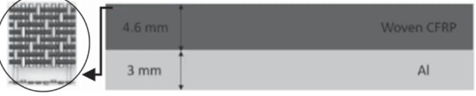
Experimental drilling tests were carried out on two hybrid stacks and a woven CFRP sheet. Al/CFRP and CFRP/Al stacks are obtained using AA 2198 and AS-4 woven CFRP plates which are closely assembled through four bolts. This type of composite is selected because of its high strength fibers and its large application in aerospace industry especially at fuselage frames and multicopters. Referenced aluminum plate is also utilized in aerospace industry. Woven CFRP plate is composed of 18 plies with the same orientation of weaving. CFRP sheet is composed of M26T prepreg Matrices HexPly and Balanced Fabrics G0939/G0802 style. It was manufactured by Hexcel composites, and it was made by Zodiac Aerospace using prepreg/autoclave technique. The size of the stack plate is 100 mm × 100 mm × 7.6 mm. The thickness of woven CFRP and aluminum alloy is 4.6 and 3 mm, respectively, as indicated in Fig.1which illustrates the schematic of the CFRP/Al section. Drilling process without lubrication has been utilized using uncoated twist carbide drill as shown in Fig.2. Special com-posite drills such as spur drills are not suitable for drilling hy-brid stacks as indicated in the literature [24]. Otherwise, normal twist drills are the most used ones by researchers to drill composite/metal stacks [25–27]. The utilized uncoated twist drill is characterized by a nominal diameter equal to 6.3 mm. It has 120°-point angle, 5° cutting angle, 11° draft angle, and 30° helix angle.
2.2 Machining tests
The drilling tests were performed on a numerical-controlled Charlyrobot CPR0705 machine. During the drilling process, the drilled material was fixed on a support including holes with 7 mm diameter. The support holes’ diameter is slightly larger than drill’s diameter in order to drill though the holes in the stack without touching the support. Indeed, this kind of support decreases the bending of drilled material and allows the produce of drilling defects at the hole’s exit side as if the stack was drilled without support. The used drilling mode in this study was without lubrication to avoid the pollution of the material. That is why the use of a vacuum cleaner is essential. Figure3
illustrates the schematic diagram of the experimental setup in the case of drilling CFRP/Al stack. Kistler 9257B dynamome-ter plate was used to record the thrust forceFz. It was fixed
under the support. The results are obtained using Kistler Dynoware software 2825D. Caggiano et al. [18] reported that the use of high values of cutting parameters may break the tool. High values of feed rate and spindle speed are not suitable for drilling Al/CFRP stack. Based on this remark, the performance of the Charlyrobot and the mechanical proprieties of the two chosen materials, the cutting parameters (feed rateVfand
cut-ting speedVc) were selected and summarized in Table1. Holes’
macroscopic observations were made using Leica binocular loupe. Holes quality was evaluated in terms of delamination holes size and surface roughness. Delamination was assessed on entry and exit sides of woven CFRP plate.
The ratio of damaged diameter over the hole diameter was used to calculate the delamination factorFdas shown in Eq.
(1). An example of delamination specimen for the calculation ofFdis presented in Fig.4. Holes inside quality were studied
by macroscopic observations. SEM observations were carried out to understand the impact of the metal part on composite one when drilling CFRP/Al and Al/CFRP stacks. CFRP and Al holes’ size was measured using a micrometer 3P15 (Swiss made). The Al hole’s surface roughness Ra was measured
using Mitutoyo S.J.201 M following the 0.8-mm stroke. Fd¼DDd
n ð1Þ
where Dd is damage diameter and Dn is hole nominal
diameter.
AS-4 woven
Fig. 1 Schematic of the CFRP/Al3 Results and discussion
3.1 Thrust force
The experimental curve of thrust force, which is captured by Kistler 9257B plate when drilling CFRP/Al stack, is shown in Fig.5. It presents the relation between the thrust forceFzand
the position of the tool’s active part in the CFRP/Al stack using a feed rate equal to 15 mm/min and a cutting speed equal to 59.346 m/min. At the beginning,Fzis equal to 0 N. When
the tool’s tip touches the CFRP plate, the thrust force increases in a linear manner until it goes through the top face of the sheet. In this case, the constant pressure exerted by the tool tip on the workpiece leads to have a cutting force equal to the pushing force. As long as the drill’s cutting part is emerged in the composite sheet, the thrust force value is nearly constant. When the cutter moved down to exit the woven CFRP plate, it touches the Al plate and goes to penetrate the second sheet. The value of the thrust force increases suddenly, and it be-comes nearly constant after the same process. Due to the dif-ference between Al and CFRP characteristics,Fzis higher in
the Al sheet than in the woven CFRP sheet. After that, the value of the thrust force decreases linearly until it reaches zero when the tool’s active part is exiting the CFRP/Al stack [12]. Same reasoning between the evolution ofFzand the tool’s
active part position in the drilled material is applied in the case of Al/CFRP stack and CFRP sheet.
The evolution of the thrust forceFz, which is recorded
during the drilling of CFRP sheet, CFRP/Al, and Al/CFRP stacks as a function of feed rateVfand cutting speedVc, is
presented in Fig.6. On one hand, taking into account that the Kistler dynamometer measuresFzvalue with an error interval
equal to 5 N, it seems that changing materials’ order in drilled stack does not affectFz. Indeed, the existence or the absence
of Al sheet in the stack does not affectFzCFRP values. This
seems logical because the variation ofFzdepend essentially of
tool’s geometry and drilled material using the same cutting parameters. Moreover, Fzrecorded during the drilling of Al
was found to be two times higher than those recorded during the drilling of woven CFRP. Indeed, the thrust force increases sharply when the drill starts to enter Al sheet. This phenome-non is due to the sudden change in material hardness of Al plate compared with woven CFRP [24]. On the other hand, regarding Fig.6a,Fzis slightly elevated with the increase of
Vfin the case of woven CFRP and Al. An increase of 40% in
theVfvalue increases theFzvalue with an average of
percent-age near to 6 and 3% in the case of woven CFRP and Al, respectively. However, this slight elevation is neglected com-pared with the dynamometer error measurement. These results are explained by the use of low feed rates generally used in grinding process. Regarding Fig. 6b, the increase ofVc
re-duces the value ofFzwhen drilling woven CFRP due to
cut-ting edges temperature rise which reduces the cutcut-ting resis-tance of epoxy matrix [28]. Indeed, increasedVc decreases
slightly Fz while drilling Al because the increase of Vc
in-creases the drilling temperature which causes the deterioration of the Al properties. An increase of 50% in theVcvalue leads
to a decrease of approximately 34 and 15% in theFzvalue in
the case of woven CFRP and Al, respectively. For example, while drilling with a feed rate of 15 mm/min, the value of the thrust force decreased from 50 to 28 N in the case of woven CFRP and from 67 to 54 N in the case Al when drilling CFRP/Al stack. Therefore, in our case, cutting speed is the most important factor influencing the thrust force no matter for woven CFRP or Al compared with feed rate.
3.2 Drilled holes quality
Drilled holes’ diameters of aluminum and composite parts in CFRP/Al, Al/CFRP stacks, and CFRP sheet were controlled by employing a 3-point internal micrometer 3P15 in order to investigate the effect of cutting parameters on diameter differ-ence. Measures were repeated four times at four different holes’ angle locations, and the average of these repeated mea-sures was taken as a final result. In the literature, there is a large difference between holes’ diameters among different layers in hybrid stacks due to the difference of mechanical and physical proprieties in each material [3]. However, in our case, their values are practically similar, and the difference
Fig. 3 Schematic diagram of the experimental setup
of holes’ diameters between Al and woven CFRP plates is neglected in the case of CFRP/Al and Al/CFRP stacks. The error is near to 0.1% between aluminum and composite parts. Indeed, by varying the machining parameters, the hole’s di-ameter remains constant for each material. The error is near to 0.6 and 0.7% compared with tool diameter for woven CFRP and Al, respectively, in CFRP sheet, CFRP/Al, and Al/CFRP stacks. This great quality of holes’ diameters for both Al and CFRP parts is explained by the use of low values of feed rate. In order to understand the influence of adding Al layer at different positions on CFRP holes’ quality, the study of de-lamination phenomenon is necessary. This kind of defects, which is not clear to the naked eye, is reported to be the most reason of composite parts’ rejection in drilling. Delamination factor was calculated based on macroscopic observation of woven CFRP holes in the drilled stacks and sheet.Fdvalues
were summarized in Fig. 7. During the drilling operation, continuous aluminum chips were produced. In the literature, the cumming out of Al chips affects the hole CFRP entry when drilling CFRP/Al stack [28]. However, in our case, the delamination phenomenon is neglected at the entrance side especially in woven CFRP sheet and CFRP/Al stack due to the low obtained values of the delamination factor. In the case of Al/CFRP stack, it is slightly increased compared with CFRP sheet and CFRP/Al stack because the generated surface of composite material is located between aluminum and com-posite layers. Regarding this stack in itself, it seems that de-lamination phenomenon at the entrance side of composite part is mainly connected to difficulties in heat generation caused
by Al part [29]. However, the cutting parameters do not influ-ence the delamination factor at the entrance side of woven CFRP whatever the stacking. Concerning the exit side of com-posite part, the delamination phenomenon is seriously present-ed especially in woven CFRP sheet comparpresent-ed with CFRP/Al and Al/CFRP stacks. It can be noted that the presence of Al sheet above or below the CFRP layer may reduce briefly the delamination phenomenon at the exit side of woven CFRP part. In our case, the lowest values of Fdis related to Al/
CFRP stack. In other words, the quality of the composite exit area is significantly improved without the Al layer support due to the efficient evacuation of Al chips from the hole. When drilling from CFRP out to Al layer, the Al chip would be occurred and accumulated in the spiral grooves and rotate with the drill bit. It may erode the matrix resin and edge delamina-tion problem at CFRP hole’s exit side [3]. Indeed, the presence of Al layer on the top of woven CFRP layer decreases more the bending of composite part compared with its absence. In other to say, fixing the composite plate between two supports (Al layer and the utilized support) is more robust than fixing it on one support. The variation of feed rate influences alsoFdat
the exit side of composite part. At low value of feed rate, almost a perfect hole is observed. Indeed, the value of delam-ination factor increases withVf. For example, when drilling
CFRP sheet, an increase of 40% in theVfvalue increases the
Fdvalue from 1.33 to 1.54. However, the variation of cutting
speedVcdoes not have significant effect. Its increase
gener-ates a slight increase ofFd. The highest damage was recorded
when usingVf= 21 mm/min andVc= 178.038 m/min. The
best results were achieved using Vf= 9 mm/min and Vc=
178.038 m/min. Based on the works of Turki et al. [30] and Ashrafi et al. [24], we notice that the cutting parameters have the same influence on the delamination factor when drilling unidirectional CFRP. Macroscopic observation of holes’ ex-ternal surfaces showed also other types of drilling defects
Fig. 5 RecordedFzduring the drilling of CFRP/Al
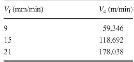
Fig. 4 Example of delamination specimen to calculate the delamination factor Table 1 Cutting parameters used in drilling tests Vf(mm/min) Vc(m/min) 9 59,346 15 118,692 21 178,038
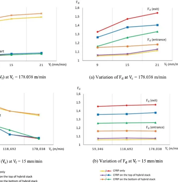
related to the hole quality in Al and woven CFRP plates when-ever the experiments started from the CFRP layer to the Al or vice versa, or it was carried on CFRP only. Figure8illustrates the entrance and the exit holes’ sides for both woven CFRP and Al plates using a scale of 2 mm at various cutting speedVc
and feed rateVfwhen drilling CFRP sheet, CFRP/Al, and Al/
CFRP stacks. Regarding the composite part, there are four types of drilling defects. We can see fraying which is present-ed by the existence of uncut fibers in the hole area, chipping which is a mark made by the drilling operation, spalling which is a delamination accompanied by tearing of a piece of ply and fuzzing which is presented by a thermal degradation of the matrix resin at the edge of the holes [5]. Fraying is sometimes accompanied by chipping. Drilling defects exist especially in the exit side of woven CFRP holes. It can be noted that
fraying, chipping, and spalling exist whenever drilling com-posite or aluminum layer first. The main reason of the appa-rition of those defects is the interaction between the cutting edge and the drilled material [31]. These surface damages are more likely presented in the case of CFRP sheet compared with CFRP/Al and Al/CFRP stacks. The existence of Al layer on the top or on the bottom of woven CFRP may reduce the appearance chronology of different types of surface damages according to interlaminar crack propagation mode: mode I, mode II, or mixed mode I + II [32]. Indeed, when drilling from the Al layer, the composite hole quality is significantly im-proved compared with other cases. The observed damages are the same as obtained in several research works such as Turki at al. [8] in the case of drilling unidirectional CFRP and Feito et al. [5] in the case of drilling woven CFRP. Fuzzing is a kind of drilling defects observed when drilling CFRP/Al stack. It is caused by the flow of CFRP and Al chips during drilling
(a) ( ) Var (b) V riatio Variat on of tion f F a of F at V at V = 17 V = 1 78.03 15 m 8 m/ mm/m /min min
Fig. 7 Variation ofFdat variousVcandVf.a Variation of FdatVc= 178.038 m/min.b Variation of FdatVf= 15 mm/min
(a) FF = f (V )) at VV = 1178.0038 mm/miin
(b) F == f (VV ) at V = 15 mmm/mmin
Fig. 6 Variation ofFzat variousVcandVf. (a) Fz= f (Vf) atVc= 178.038 m/min; (b) Fz= f (Vc) atVf= 15 mm/min
which produced a washing out effect of the shim material [31]. It is presented at the exit side of woven CFRP when drilling CFRP/Al stack in the case of Vf = 15 mm/min andVc=
59.346 m/min although these values of cutting parameters are not the highest in this study. This case presents also the
highest average of thrust force. The relation between the ther-mal degradation and the cutting conditions is not as indicated in the literature. Wang et al. noted that the drilling temperature has increased with the increase of spindle speed, and it has decreased with the increase of feed rate [3]. However, in our case, it seems that this conclusion does not work because we have drilled the stack using a very low value of machining parameters. Another phenomenon specific to metallic part fig-ures in our study. It is the formation of burrs with a very small length at the exit side of the Al sheet when drilling CFRP/Al stack. This phenomenon is similar to the formation of chips. It nags the aerospace industry because burrs are very difficult to remove, and its removal can seriously damage the workpiece. In the literature, the formation of burr is related to the value of feed rate. Indeed, the length of burr at the exit side is higher than at the entrance one when drilling only Al sheet [33]. In our case, the burrs at the entrance side were disappeared, and the length of the obtained burrs is neglected compared with those obtained in the literature due to the lowest values of the utilized feed rate [34–36]. Regarding Al/CFRP stack, a neatly and sharp hole edge was obtained in the entrance and the exit side of Al sheet. We also noted the existence of CFRP chips on the exit side and the inside of Al holes which may influence the Al surface quality at the inside of the hole. To understand the influence of one-shot drilling operation on each configu-ration of hybrid stacks, the study of interior holes surfaces’ quality is important because it influences the precision assem-bly of avionics components. For the Al layer, the holes’ sur-face roughnessRahave been measured on the hole
longitudi-nal direction. The value ofRais the average of six
measure-ments taken at different surface locations. Currently, the Al surface roughness was considered acceptable in aviation in-dustries when it was lower than 1.6 mm [3]. In our case, it did not exceed 4.5μm. Surface roughness results of the Al holes at different feed rate and cutting speed are shown in Fig.9. The results revealed, for both CFRP/Al and Al/CFRP stacks, thatVfandRavary proportionally, andVcandRavary
inverse-ly. Furthermore, the effect of cutting parameters on the surface roughness value is similar to thrust force evolution. The rea-son attributing to this remark is that, by increasing the feed rate, the voids surrounding the particles join up and cause chip segmentation. Indeed, increasing the cutting speed only leads to ductile tearing of the homogeneous metal chips [37]. For Al/CFRP, we notice that the interior surface state was im-proved compared with CFRP/Al. In fact, drilling the Al layer at the first reduces the surface roughness value despite the flow of CFRP chips through the already drilled hole which may lead to chip clogging [31]. However, CFRP is a bad conductor of heat. Drilling the composite layer at the first increases the tool’s temperature, due to the absence of lubri-cation, and it damages the holes’ interior surface quality. In order to investigate the interior surface morphologies for both Al and CFRP holes at various machining parameters,
Entrance of woven CFRP sheet Exit of woven CFRP sheet
V = 9 mm/min and V = 178.038 m/min
V = 15 mm/min and V = 178.038 m/min
V = 21 mm/min and V = 178.038 m/min
V = 15 mm/min and V = 59.346 m/min
V = 15 mm/min and V = 118.692 m/min (a) CFRP sheet CFRP CFRP Fraying Fraying Fraying Chipping Chipping Chipping Chipping Spalling Spalling Spalling
Fig. 8 Macroscopic observation of woven CFRP and Al holes’ sides. a CFRP sheet,b CFRP/Al stack, c Al/CFRP stack
Entrance of woven CFRP sheet Exit of woven CFRP sheet Entrance of Al sheet Exit of Al sheet
V = 9 mm/min and V = 178.038 m/min
V = 15 mm/min and V = 178.038 m/min
V = 21 mm/min and V = 178.038 m/min
V = 15 mm/min and V = 59.346 m/min
V = 15 mm/min and V = 118.692 m/min
(b) CFRP/Al stack Fraying Spalling Fuzzing Chipping Burr CFRP Al CFRP Al CFRP Al CFRP Al Chipping Spalling Fraying Fraying Spalling Spalling Burr Burr Burr Burr Fig. 8 (continued)
Entrance of Al sheet Exit of Al sheet Entrance of woven CFRP sheet Exit of woven CFRP sheet
V = 9 mm/min and V = 178.038 m/min
V = 15 mm/min and V = 178.038 m/min
V = 21 mm/min and V = 178.038 m/min
V = 15 mm/min and V = 59.346 m/min
V = 15 mm/min and V = 118.692 m/min
(c) Al/CFRP stack Al CFRP Al CFRP Al CFRP Al CFRP CFRP chips CFRP chips CFRP chips Fraying Fraying Chipping Chipping Spalling Fig. 8 (continued)
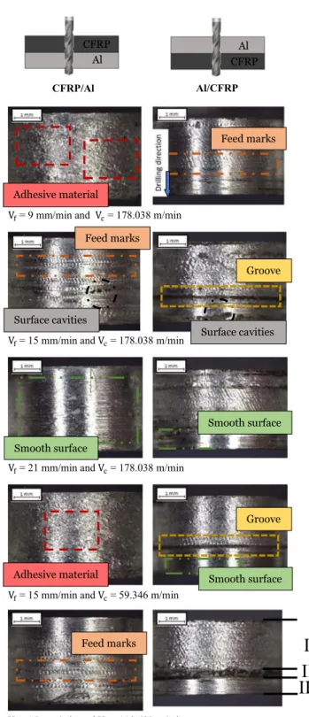
macroscopic observations of the interior holes’ surfaces were done using a scale of 1 mm. Figure10 presents Al holes’
profiles at various cutting speedVcand feed rateVffor both
stacks. Regarding the Al layer in the CFRP/Al stack, adhesive material appears in the hole’s surface profile due to the ab-sence of lubrication. Temperature increasement of the utilized drilling tool changes the Al mechanical characteristics and causes a bad material removal technique. This kind of defects is also observed in several research works [38,39]. Smooth surfaces appear especially when drilling Al/CFRP stack. In fact, changing the drilling sequence of the hybrid stack influ-ences the drilling process and the quality of drilled surfaces. It can be seen also other drilling defects like feed marks and surface cavities whenever drilling composite or aluminum layer first. The rotation of Al chips with the drill bit causes the apparition of grooves when drilling Al layer first in the hybrid stack. The biggest obtained groove width is near to 0.7 mm atVf= 15 mm/min andVc= 118.692 m/min. We also
have the impression that the Al surface state in Al/CFRP stack is subdivided into three parts: adhesive material, groove, and smooth surfaces. The apparition of smooth surfaces near to the hole exit side is related to the decreasing temperature of dril-ling tool caused by Al material. In fact, Al is a good heat conductor. It can therefore reduce the drilling toll’s tempera-ture. Regarding the composite part, Fig.11illustrates woven
CFRP/Al Al/CFRP
V = 9 mm/min and V = 178.038 m/min
V = 15 mm/min and V = 178.038 m/min
V = 21 mm/min and V = 178.038 m/min
V = 15 mm/min and V = 59.346 m/min
= 15 mm/min and = 118.692 m/min
II
Adhesive material Feed marks Surface cavities Groove Smooth surface Al CFRP CFRP Al Adhesive material Feed marks Feed marks Smooth surface Groove Surface cavities Smooth surfaceIII
I
Fig. 10 Interior macroscopic observation of Al part (a) R = f (V ) at V = 178.038 m/min
(b) R = f (V ) at V = 15 mm/min
Fig. 9 Variation ofRaat variousVcandVf. (a) Ra= f (Vf) atVc= 178.038 m/min.b Ra= f (Vc) atVf= 15 mm/min
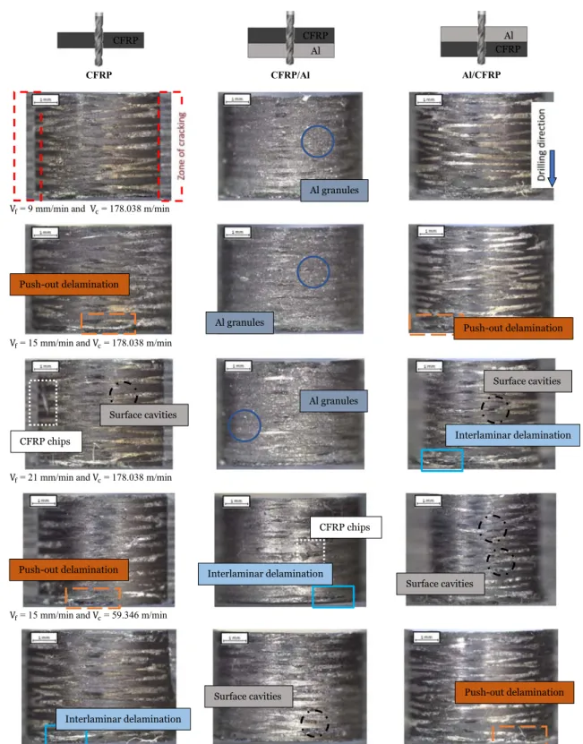
CFRP holes’ profiles at various cutting speed Vcand feed rate
Vfwhen drilling CFRP sheet, CFRP/Al, and Al/CFRP stacks.
Whatever the kind of drilling process, the cut woven CFRP profiles show drilling defects like surface cavities, interlami-nar delamination, and push-out delamination. These damages
are similar to those obtained when drilling unidirectional CFRP [40].
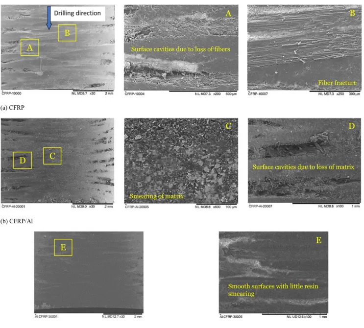
As our eyes are too small to notice the difference between surface morphologies, SEM analysis were made on woven CFRP holes under different drilling process using Vf=
CFRP CFRP/Al Al/CFRP
V = 9 mm/min and V = 178.038 m/min
V = 15 mm/min and V = 178.038 m/min
V = 21 mm/min and V = 178.038 m/min
V = 15 mm/min and V = 59.346 m/min
= 15 mm/min and = 118.692 m/min
Al granules Push-out delamination Surface cavities CFRP chips Interlaminar delamination CFRP CFRP CFRP Al Al Push-out delamination Al granules Al granules Surface cavities Interlaminar delamination CFRP chips
Push-out delamination Interlaminar delamination
Push-out delamination Surface cavities
Surface cavities
15 mm/min andVc= 59.346 m/min. SEM observations are
presented in Fig.12. It can be noted that surface cavities, which are presented in figure A and D, could be created due to loss of fibers or matrix. They are localized on both sides of the hole. Fractured fibers exist in the middle like presented in figure B. Eneyew et al. [41] have noted that the drilling of unidirectional CFRP [90°]33provide the most serious defects
in two specific regions which are located at 135 and 315° from hole’s diameter. The selected hole’s diameter is perpendicular to composite fiber direction. It seems logic in our case to found surface cavities at− 45 and 45° from hole’s diameter because the utilized CFRP material is composed of weaving fibers initially oriented at 0 and 90°. Regarding the observed holes, it can be noted that adding Al sheet on the top or on the
bottom of CFRP sheet reduces the size of surface cavities. Indeed, the surface cavities are practically absent in the case of Al/CFRP stack, and the surface quality is smooth with little resin smearing, like presented in figure E, because the CFRP layer exist between two supports. However, the existence of Al layer on the bottom of CFRP layer causes matrix smearing like presented in figure C due to the flow of Al chips during drilling process.
4 Conclusion
In this paper, a study of the influence of adding AA 2189 sheet to AS-4 woven CFRP sheet at various positions have been
(a) CFRP (b) CFRP/Al (c) Al/CFRP
A
B
C
C
D
D
E
Smearing of matrixSurface cavities due to loss of matrix Surface cavities due to loss of fibers
Fiber fracture
Smooth surfaces with little resin smearing
E
A
B
carried out using specific condition of cutting parameters. The choice of materials was based on what used nowadays in the aircraft structure. This work gives some idea about the influ-ence of machining conditions on hybrid stack drilling defects. The following conclusions can be drawn. Layers’ positions in hybrid stacks do no effect thrust force evolution. Its increased value is related to enhanced risk of woven CFRP epoxy matrix thermal degradation when drilling CFRP/Al stack, and it causes also a bad roughness surface of the Al holes. Cutting speed has been the most responsible one of the delamination phenomenon augmentations, and it is the most important fac-tor influencing the thrust force no matter for woven CFRP or Al due to feed rate low values in our study. Changing the material order in the hybrid stack influences the holes surface quality. Making Al layer on the bottom causes the smearing of composite matrix. However, it causes groove in the Al hole when it is on the top. Adding Al layer on the top of woven CFRP reduces the apparition of drilling defects and delamina-tion phenomenon especially at the hole exit side. So, drilling composite material between two supports improves hole qual-ity even with the use of twist drill bit. As a perspective, it seems very important to study the effect of temperature evo-lution when drilling hybrid stacks on holes surface quality in future works and to validate our results by analytical and nu-merical modeling.
Acknowledgments This work is partially supported by Laboratory of Applied Fluid Mechanics, Environment and Process Engineering. Sincere thanks are extended to Zodiac aerospace for the CFRP plates, Laboratory of Innovation Technology for the drills and their support for doing experimental tests in good conditions and Toulouse University for the realization of SEM observations. The authors also gratefully acknowl-edge the helpful comments and suggestions of the reviewers, which have improved the presentation.
References
1. Geng D, Liu Y, Shao Z et al (2020) Delamination formation and suppression during rotary ultrasonic elliptical machining of CFRP. Compos B 183:107698.https://doi.org/10.1016/j.compositesb. 2019.107698
2. Jia ZY, Chen C, Wang FJ, Ma JW, Yang F (2018) Three-dimensional oblique cutting model for sub-surface damage analysis in CFRP/Ti stack composite machining. Int J Adv Manuf Technol 96:643–655.https://doi.org/10.1007/s00170-018-1626-5
3. Wang CY, Chen YH, An QL et al (2015) Drilling temperature and hole quality in drilling of CFRP/aluminum stacks using diamond coated drill. Int J Precis Eng Manuf 16(8):1689–1697.https://doi. org/10.1007/s12541-015-0222-y
4. Soutis C (2015) Introduction: engineering requirements for aero-space composite materials, Elsevier. Polymer Compos Aeroaero-space Industry.https://doi.org/10.1016/B978-0-85709-523-7.00001-3
5. Feito N, Diaz-Alvarez J, Diaz-Alvarez A et al (2014) Experimental analysis of the influence of drill point angle and wear on the drilling of woven CFRPs. Materials 7:4258–4271.https://doi.org/10.3390/ ma7064258
6. Qui X, Li P, Niu Q et al (2018) Influence of machining parameters and tool structure on cutting force and hole wall damage in drilling CFRP with stepped drills. Int J Adv Manuf Technol 97:857–865.
https://doi.org/10.1007/s00170-018-1981-2
7. Li M, Leung Soo S, Aspinwall DK et al (2018) Study on tool wear and work piece surface integrity following drilling of CFRP lami-nates with variable feed rate strategy. Sci Direct Proc CIRP 71:407– 412
8. Turki Y, Habak M, Velasco R et al (2014) Experimental investiga-tion of drilling damage and stitching effects on the mechanical behavior of carbon/epoxy composites. Int J Mach Tools Manuf 87:61–72
9. Mahdi A, Turki Y, Bouaziz Z, Habak M., Bouami S.E. (2019) Experimental effect of cutting parameters and tool geometry in drilling woven CFRP, advances in mechanical engineering and mechanics. CoTuMe 2018. Lecture notes in mechanical engi-neering. Springer, Cham doi: https://doi.org/10.1007/978-3-030-19781-0_17
10. Mrazova M (2013) Advanced composite materials of the future in aerospace industry. INCAS BULLETIN 5(3):139–150 ISSN 2066-8201
11. Luo B, Li Y, Zhang K, Cheng H, Liu S (2014) A novel prediction model for thrust force and torque in drilling interface region of CFRP/Ti stacks. Int J Adv Manuf Technol 81:1497–1508.https:// doi.org/10.1007/s00170-015-7294-9
12. Dang J, Zou F, Cai X, An Q, Ming W, Chen M (2019) Experimental investigation on mechanical drilling of a newly developed CFRP/Al co-cured material. Int J Adv Manuf Technol 106:993–1004.https:// doi.org/10.1007/s00170-019-04659-1
13. Liu S, Qi Z, Li Y et al (2016) On full life-cycle instantaneous force predicting when drilling CFRP-metal stacks. Int J Adv Manuf Technol 88:651–661.https://doi.org/10.1007/s00170-016-8794-y
14. Fernandez-Vidad SR, Fernandez-Vidad S, Batista M et al (2018) Tool Wear mechanism in cutting of stack CFRP/UNS A97075. Materials 11:1276.https://doi.org/10.3390/ma11081276
15. Hassan MH, Abdullah J, Mahmud AS et al (2018) Effects of twist drill geometry and drilling parameters on CFRP-aluminum stack up in single shot drilling. SciFed J Mater Res Lett 2(2):1–14 16. El Bouami S, Habak M, Velasco R et al (2017) Tool geometry
optimization for drilling CFRP/Al-Li stacks with a lightning strike protection. AIP Conference Proc 1896:090009.https://doi.org/10. 1063/1.5008116
17. El Bouami S, Habak M, Franz G et al (2016) Effect of tool geom-etry and cutting parameters on delamination and thrust forces in drilling CFRP/Al-Li. AIP Conference Proc 1769:080012.https:// doi.org/10.1063/1.4963487
18. Caggiano A, Napolitano F, Nelec L et al. (2019) Study on thrust force and torque sensor signals in drilling of Al/CFRP stacks for aeronautical applications, 12th CIRP Conference on Intelligent Computation in Manufacturing Engineering, 18–20 July 2018, Italy, Procedia CIRP, vol. 79, pp. 337–342
19. Angelone R, Caggiano A, Improta I et al. (2019) Characterization of hole quality and temperature in drilling of Al/CFRP stacks under different process condition, 12th CIRP Conference on Intelligent Computation in Manufacturing Engineering, 18–20 July 2018, Italy, Procedia CIRP, vol. 79, pp. 319–324
20. Robbany F, Pramujati B, Suhardjono et al. (2019) Multi response prediction of cutting force and delamination in carbon Fiber rein-forced polymer using backpropagation neural network-genetic al-gorithm, AIP Conference Proceedings 2114, 030012. doi:https:// doi.org/10.1063/1.5112416
21. Feito N, Milani AS, Muñoz-Sánchez A (2015) Drilling optimiza-tion of woven CFRP laminates under different tool wear condioptimiza-tions: a multi-objective design of experiments approach. Struct Multidiscip Optim 53:239–251. https://doi.org/10.1007/s00158-015-1324-y
22. Harranen H, Kers J, Preden JS et al (2014) Embedded electronics influence on the strength of carbon fiber laminate. Adv Mater Res 905:239–243.https://doi.org/10.4028/www.scientific.net/AMR. 905.239
23. Kers J and Majak J (2008) Modelling a new composite from a recycled GFRP, Mechanics of Composite Materials, vol. 44, no. 6 24. Ashrafi SA, Sharif S, Farid AA et al (2014) Performance evaluation
of carbide tools in drilling CFRP-Al stacks. J Compos Mater 48(17):2071–2084.https://doi.org/10.1177/0021998313494429
25. Brinksmeier E, Fangmann S, Rentsch R (2011) Drilling of compos-ites and resulting surface integrity. CIRP Annals Manuf Technol 60: 57–60
26. Neugebauer R, Ben-Hanan U, Ihlenfeldt S et al (2012) Acoustic emission as a tool for identifying drill position in fiber-reinforced plastic and aluminum stacks. Int J Mach Tools Manuf 57:20–26 27. Park K-H, Beal A, Kim D et al (2011) Tool wear in drilling of
composite/titanium stacks using carbide and polycrystalline dia-mond tools. Wear 271:2826–2835
28. Zitoune R, Krishnaraj V, Collombet F (2010) Study of drilling of composite material and aluminum stack, Elsevier. Compos Struct 92:1246–1255
29. Merzouki J, Poulachon G, Rossi F et al. (2017) Method of hole shrinkage radial forces measurement in Ti6Al4V drilling, 16th CIRP Conference on Modelling of Machining Operations, Procedia CIRP, vol. 58, pp. 629–634
30. Turki Y, Habak M, Velasco K et al (2014) Influence of cutting forces and damage on 2D and 3D carbon/epoxy composites in drilling. Key Eng Mater 611-612:1217–1225.https://doi.org/10. 4028/www.scientif.net/KEM.611-612.1217
31. Wertheim R, Ben-Hanan U, Ihlenfeldt S et al (2012) Acoustic emis-sion for controlling drill position in fiber-reinforced plastic and metal stacks. CIRP Ann Manuf Technol 61:75–78.https://doi.org/ 10.1016/j.cirp.2012.03.003
32. Aboura Z (1993) Etude du processus de délaminage mode I, mode II et mode mixte (I+II) de matériaux composites à renforts tissés à différentes vitesses de sollicitation, thesis book, Compiègne 33. Wei T, Jian H, Wenhe L et al (2016) Formation of interlayer gap and
control of interlayer burr in dry drilling of stacked aluminum alloy
plates. Chin J Aeronaut 19(1):283–291.https://doi.org/10.1016/j. cja.2015.11.002
34. Brinksmeier E and Fangmann S (2009) Burr and cap formation by orbital Drilling of Aluminum, proceedings of the CIRP internation-al conference on burrs, pp. 31-44, University of Kaiserslautern, Germany
35. Soo SL, Abdelhafeez AM, Li M et al (2017) The drilling of carbon fiber composite–aluminum stacks and its effect on hole quality and integrity, proceedings of the institution of mechanical engineers, Part B: Journal of Engineering Manufacture, pp 1–9.https://doi. org/10.1177/0954405417728312
36. Heisela U and Pfeifrothb T (2012) Influence of point angle on drill hole quality and machining forces when drilling CFRP, science direct, 5th CIRP conference on high performance cutting, pp. 471–476
37. El Gallab M, Sklad M (1998) Machining of Al/SiC particulate metal matrix composites part II: workpiece surface integrity, Elsevier. J Mater Process Technol 83:277–285
38. Zhang L, Liu Z, Tian W, Liao W (2015) Experimental studies on the performance of different structure tools in drilling CFRP/Al alloy stacks. Int J Adv Manuf Technol 81:241–251.https://doi.org/10. 1007/s00170-015-6955-z
39. Uddin M, Basak A, Pramanik A et al (2018) Evaluating hole quality in drilling of Al 6061 alloys. Materials 11:2443.https://doi.org/10. 3390/ma11122443
40. Xu J, Zhou L, Chen M et al (2019) Experimental study on mechan-ical drilling of carbon / epoxy composite - Ti6Al4V stacks. Mater Manuf Process.https://doi.org/10.1080/10426914.2019.1594275
41. Eneyew ED, Ramulu M (2014) Experimental study of surface qual-ity and damage when drilling unidirectional CFRP composites. J Mater Res Technol 3(4):354–362.https://doi.org/10.1016/j.jmrt. 2014.10.003
Publisher’s note Springer Nature remains neutral with regard to jurisdic-tional claims in published maps and institujurisdic-tional affiliations.