HAL Id: hal-01240349
https://hal.archives-ouvertes.fr/hal-01240349
Submitted on 9 Dec 2015HAL is a multi-disciplinary open access archive for the deposit and dissemination of sci-entific research documents, whether they are pub-lished or not. The documents may come from teaching and research institutions in France or abroad, or from public or private research centers.
L’archive ouverte pluridisciplinaire HAL, est destinée au dépôt et à la diffusion de documents scientifiques de niveau recherche, publiés ou non, émanant des établissements d’enseignement et de recherche français ou étrangers, des laboratoires publics ou privés.
2.5D braided interlock composite tubes under crush
loading.
Cyril Priem, Ramzi Othman, Patrick Rozycki, Damien Guillon, Antoine
Martin
To cite this version:
Cyril Priem, Ramzi Othman, Patrick Rozycki, Damien Guillon, Antoine Martin. Analytical and numerical simulation of the behavior of 2.5D braided interlock composite tubes under crush load-ing.. ECCM16 - 16th European Conference on Composite Materials, Jun 2014, Sevilla, Spain. �hal-01240349�
ANALYTICAL AND NUMERICAL SIMULATIONS OF THE
BEHAVIOUR OF 2,5D-BRAIDED INTERLOCK COMPOSITE TUBES
UNDER CRUSH LOADING
Cyril PRIEMa, Ramzi OTHMANa, Patrick ROZYCKIa*, Damien GUILLONb, Antoine MARTINa
a
GeM, Institut de Recherche en Génie Civil et Mécanique (UMR CNRS 6183) ECOLE CENTRALE DE NANTES, 1 rue de la Noë, B.P. 92101 F-44321 Nantes Cedex 3
b
CETIM / pôle Ingénierie Polymères & Composite, Technocampus EMC2, Z.I. du Chaffault, 44340, Bouguenais
*Patrick.Rozycki@ec-nantes.fr
Keywords: crashbox, thermoplastic composite, 2,5D-braided, simulation
Abstract:
This article deals with the experiment and numerical simulation of the crash of composite tubes made of 2,5D-braided composite. In a first part, we present the material characterization at different strain rates as well as the results of tubes which have been tested in a drop-weight tower. In a second part, we describe the bi-phase material model which has been developed. It is based on Drozdov’s modelling for thermoplastic matrix and on the kinking modelling for fibers. In a last part, we present the experiment and numerical simulations correlations and we will conclude more particularly about the good predicting the value of energy absorption.
1. Introduction
A major issue for car manufacturers is to decrease the fuel consumption of vehicles and the CO2 emissions. Among all the prospected solutions, one consists in the reduction of the
vehicle weight. Due to their properties, composite materials appear to be good candidates for structural parts such as energy absorbers. Indeed, replacing these pieces, usually made of metallic, could lead to gain around 3 times the weight of these structural parts. However, the complexity of the composite behavior (from quasi-static to dynamic) poses the problem of possessing reliable numerical tools in order to well predict their capacity to absorb energy during the crash. This paper presents some work done in this direction.
For many years, the mechanical behavior of metallic tubes during a crash is well understood. Alghamdi et al. [1] has done an overview on the behavior of metallic energy absorbers. They have described several modes of energy dissipation and have also suggested some analytical models which have been validated. El-Hage et al. [2] have studied the crash of rectangular aluminum tubes in the numerical point of view using LS-DYNA software. This model has also been used by Yamazaki et al. [3] to optimize the structural parameters of square and circular metallic tubes. A literature overview of crash simulations of metallic tubes by Jones
et al.[4] pointed also the problem of elastic and plastic stress waves propagation and their huge influence on the structural response of en energy absorber. They insisted on needed further studies to predict accurately the dynamic inelastic failure of metallic materials. In order to decrease weight of crushing tubes, different attempts have also been made to combine metallic and composite materials, such as filling metallic tubes with foams [5] or by wrapping them with fibers [6].
The crashing of tubes made of only composite materials has also been studied. Due to their lower viscosity, thermosetting matrix are more often studied and used for energy absorbers. One of the most studied composite materials is made of carbon fibers and epoxy resin. Obradovic et al. [7] used LS-DYNA Material models 54 and 55 to simulate the brittle behavior of this material. They obtained a 10% close prediction of the energy dissipated by a circular tube. The same material model has been used by Deleo et al. [8] to obtain a close match with a parameter study on square carbon/epoxy composite tubes. Greve at al. [9] uses the enhanced Ladevèze–Puck model (LP) for global ply fracture and the energy absorbing contact (EAC) implemented in PAM-CRASH. This model works only for a fragmentation mode of dissipating energy, which doesn’t occur with thermoplastic composite. Zarei et al. [10] used material model 54 of LS-DYNA to simulate the crash of woven glass fibers/polyamide composite crash boxes. They get a precise prediction of the energy absorbed but not of the mode of energy dissipation. A problem with these materials is the laminate fracturation which is a low energy dissipation phenomenon. Composites with 3D fibers structures and thermosetting matrix have been introduced to solve this issue and models have been developed to simulate their behavior during lateral impact [11, 12] but not the crash of tubes.
The purpose of this paper is dedicated to experimental and numerical studies of the crash of circular 2,5D-braided thermoplastic composite tubes. We can notice that this is an innovative concept in regard of the current literature and particularly due to the fact that thermoplastic resin with 2.5D fiber structure is investigated and modeled. In a first part, the experiments about the material characterization and the crash behavior of tube are presented. In a second part, the model based on bi-phase material as well as its implementation within a VUMAT, are explained. We will conclude by the comparisons between experimental and numerical results.
2. Materials and Experiments
2.1. Materials
The material of interest is called Twintex®. It is made of a comingled glass fibers and polypropylene matrix. The 2,5D-braided reinforcements were realized by DJP with ply by ply interlocked bias fibers. The produced fiber configurations was 320 doubled axial fibers and 320 simple fibers oriented at ±45°. All tubes were braided on a 120 mm-mandrel and consolidated under an air-empty bag in an oven at a temperature of 210°C. A thermal duct was used to avoid folds of the braided composite. The cylindrical composite tubes are either 100 (V-45-1 and V-45-2) or 200 mm long (V2-45-1 and V2-45-2). The inner and outer diameters are 116.5 and 123.5 mm respectively.
Concerning the material characterization, one braided tube has been cut and unfolded before the curing. The plate was then consolidated at 210°C. Test samples have been cut out with a 3 mm-reamer: 40*20*3.5 mm for quasi-static traction and 25*20*3.5 mm for dynamic trials. Three standard directions for the testing samples have been chosen: 0°, 45°, 90°.
2.2 Experimental setup
Crushing tests were carried out by using a drop-weight tower. A 319 kg mass can fall from a height of 1.3 (V tubes) and 3.4 m (V2 tubes) for an energy of 4070 and 10650 J respectively. The tubes are fixed with rivets and instrumented with a force transducer. The crash is filmed by a synchronized Photron SA1 high speed video camera. Images are stored at a frequency rate of 4000 pictures per second and combined with an accelerometer give us the displacement of the falling mass.
A 100kN INSTRON test rig is used to process static experiment. The strain rate during traction tests was 10-3 s-1. Medium strain rates tests (0.1 and 1 s-1) are conducted on MTS test rig.Dynamic tests (100 and 300s-1) are carried out by using a crossbow system. The same high speed video system is used and image correlation software gives us the deformation field of the test coupon. The local stress is given by the division of the force given by the test rigs transducer by the coupons section.
2.3. Experimental results
2.3.1. Traction
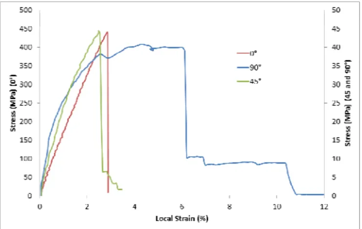
Tensile test gives the strain-stress curve of the material:
Figure 1. Quasi-static traction curves
Several behaviors can be noticed: at 0°, the material behavior is almost elastic brittle. For the two others directions, the behavior is non-linear, with an important plastic part of the strain.At O°, increasing the strain rate doesn’t influence the value of Young modulus (16GPa) but increases the ultimate tensile stress and the ultimate tensile strain.
Strain rate (s-1) 0,00016 134 278 Young modulus (MPa) 16321 16772 16703 Ultimate tensile strain (%) 2.82 2.94 6.91
Table 1. Young modulus values at different strain rates at 0°
At 45° and 90°, shear and Young modulus as ultimate strain and stress are increasing while the strain rate is increasing. This is due to the influence of strain rate on the behavior of thermoplastic resins.
Figure 2. Ultimate shear strain and stress at several strain rates
2.3.2. Crash test
Several crash tests have been performed:
Trial Orientation Impact angle (°) Fmax (N) Fave (N) SEA (J/kg)
V2-45-1 45 0 96527 49452 23097
V2-45-2 45 0 106762 46873 22408
V-45-1 45 0 87376 71351 34331
V-45-2 45 0 143432 73377 34546
Table 2. Crushing tests of tubes made on the drop-weight tower
The energy was dissipated according to a mode called “splaying mode”. The tube is forced by the impacting mass to increase its diameter leading to a circumferential deformation and to the propagation of vertical cracks.
.Figure 3. Picture of the splaying mode of energy dissipation
The specific energy absorbed (SEA) was calculated:
(
2 1)
(
2 1)
2 1δ
δ
ρ
δ
δ
δ
ρ
δ δ − = − =∫
A d F A W SEA (1)WhereW , ρ ,
δ
2,δ
1 andAhold for the absorbed energy, composite material density, boundaries of the interval of stable crushing and cross-sectional area of the tube, respectively. The SEA value is around 30 kJ/kg which is the same performance as metallic tubes.From crash test the force-displacement curve can be drawn as figure 4:
Figure 4. Force-displacement curve of the crash of composite tubes 3. Composite behavior law and its implementation
To be more adaptive and to adapt to the law for thermoplastic behavior, the model developed is biphasic: the calculation of fibers and matrix strain and strength are separated. The fibers have an elastic brittle behavior and only the strain in fibers direction is considered. The different orientations of the strands of fibers are considered and uncoupled. A damage model is used to obtain a progressive breaking of the fibers between two user-defined values of strain. For oriented strands of fibers, global strains are projected in the fibers coordinate system. Fibers stress and damage is calculated and projected in the global coordinates.
To better simulate the behavior of fibers under compression a kinking model is used. The angular acceleration of fibers is determined by application of the principle of virtual work on a basic element. Strains induced by this phenomenon are introduced in the strain matrix calculations.
The matrix calculations are based on the model of Drozdov for the behavior of thermoplastic [13]. This model uses a quasi-incompressible formulation. Stresses and strains have to be split in deviatoric and hydrostatic part. An elastic plastic separation is done for the deviator part while the hydrostatic part is considered as fully elastic. The elastic strain represents a polymer strand stretch and plastic strain describes polymer strand slippage. Two cases are defined: active loading if the deformation reached the highest value which has ever occurred and loading-reloading if not. The plastic deformation is calculated using the function ϕ according to these equations: )/dt (t)(d = )/dt (d
ε
mat pφ
ε
mat' (2)0 = (0) , ) -1 ( A = /dt dφ φ B φ (3) 0 A |, /dt d | A = A
ε
≥ (4) ) ) / ln( B + (1 B = B 0 m×ε
&ε
&0 (5)Making the hypothesis that internal energy is the sum of elastic energy for each polymer strand averaged on the medium plus an hydrostatic term and using the inequality of Clausius-Duhem: )I Tr( K + ) -1 ( 2 = m mat e mat
µ
φ
ε
ε
σ
′ (6)Where
µ
mis the modulus of the matrix for the deviatoric part and K the modulus for the hydrostatic pressure.µ
mdepends of the strain rate as the B parameter. The calculation of the homogenized stress is done using a Reuss model and the volumic ration of matrix in the composite Vm: ) + )(1 + (1 V + ) + )(1 + (1 Vm)) -(1 ( = 2 transverse 1 m matrix 2 transverse 1 fibre hom ε ε σ ε ε σ σ transverse transverse (7)The material has been implemented in Abaqus using a VUMAT. An explicit method of integration has been chosen with a Newmark scheme. The programming language is Fortran90 and the compiler is Intel Fortran Compiler.
4. Validation
4.1. Tensile tests
To verify the validity of our model, simulations of tensile tests have been realized. Using the software Abaqus, first tests were made on a unique 3D element with a linear interpolation. One face was blocked for the direction of traction. On the opposite face was imposed a constant velocity. Several material orientations and deformation rates have been tested. A good coherence with the experimental results has been found.
Figure 5. Experimental and simulation curves for quasi-static traction curve at 0°
To validate our model, the tensile tests have been fully represented. The same elements have been used. Using different orientations and deformations rates, the material model have been validate.
4.2. Drop-weight tower tests
Using the same software, we simulate the crash of circular tubes. To reduce CPU time cost, only an eighth of the tube is represented and bigger elements are used far from the impact area. An eighth is enough considering that the splaying mode presents a cylindrical symmetry. Symmetry boundary conditions are used. The support and the impacting weight are
represented by two rigid plans. The first one is embedded. The impacting weight have been imposed a vertical speed and a mass corresponding of an eighth of the real one.
Figure 6. Simulation of drop-weight tower test
The simulation of a crash of a composite tube is still in development. More work are needed to get a satisfying prediction of the crushing and of the performances of the tube.
5. Conclusion
A material model has been developed to simulate the behavior of 2.5D braided composite with glass fibers and a polypropylene matrix. The material has been characterized using tensile tests at different deformation rates. A VUMAT model of material has been developed for Abaqus simulations. As a biphasic model, fibers and matrix calculations are separated then combined using a Reuss model. The kinking of the fibers is implemented. A visco-elastoplastic model is used for the matrix. Simulations of the tensile tests have been realized and the material model has been validated. Used to simulate the crash of the tubes, the material model will give a good prediction of the mode of energy simulation and of the
performances of the energy absorber. To go further, simulations with other materials can be done to evaluate the potential of the model and its domain of validity. Another perspective is the development of an analytical model to get the mean crush force of a tube.
References
[1] A.A.A. Algahmdi Collapsible impact energy absorbers: an overview Thin-Walled Structures, 39: 189-213, 2001
[2] H. El-Hage, P.K. Mallick and N. Zamani A numerical study on the quasi-static axial crush of square aluminum tubes with chamfering and other triggering mechanisms International Journal of Crashworthiness, 10:2 183-196, 2010
[3] K. Yamazaki Maximization of the crushing enrgy absorption of tubes Structural Optimization, 16, 37-46, 1998
[4] N. Jones Several phenomena in structural impact and structural crashworthiness European Journal of Mechanics, A/Solids 22? 693-707, 2003
[5] Z. Ahmad, D.P. Thambiratnam and A.C.C. Tan Dynamic energy absorption characteristics of foam-filled conical tubes under oblique impact loading International Journal of Impact Engineering, 37, 475-488, 2010
[6] H.W. Song, Z.M. Wan, Z.M. Xie and X.W. Du Axial impact behavior and energy absorption efficiency of composite wrapped metal tubes International Journal of Impact Engineering, 24, 385-401, 2000
[7] J. Obradovic, S. Boria and G. Belingardi Lightweight design and crash analysis of composite frontal impact energy absorbing structures Composite Structures, 94, 423-430, 2012
[8] F. Deleo, B. Wade and P. Feraboli Crashworthiness of composite structures: Experiments and Simulation In JAMS 2010
[9] L. Greve and A.K. Pickett Modelling damage and failure in carbon/epoxy non-crimp fabric composites including effects of fabric pre-shear Composites, Part A 37, 1983-2001, 2006
[10] H. Zarei, M. Kröger and H. Albertsen An experimentall and numerical crashworthiness investigation of thermoplastic composite crash boxes Composite Structures, 85, 245-257, 2008
[11] M. Pankow, A.M. Waas, C.F. Yen and S. Ghiorse Shock loading of 3D woven composites: A validated finite element investigation Composite Structures, 93, 1347-1362, 2011
[12] W. Hufenbach, M. Gude, C. Ebert, M. Zscheyge and A. Hornig Strain rate dependent low velocity impact response of layerwise 3D-reinforced composite structures International Journal of Impact Engineering, 38, 358-368, 2011
[13] A.D. Drozdov Multi-cycle viscoplastic deformation of polypropylene Computational Materials Science, 50, 1991-2000, 2011